EP0066016A1 - Appareil pour la distribution et l'évacuation - Google Patents
Appareil pour la distribution et l'évacuation Download PDFInfo
- Publication number
- EP0066016A1 EP0066016A1 EP81302314A EP81302314A EP0066016A1 EP 0066016 A1 EP0066016 A1 EP 0066016A1 EP 81302314 A EP81302314 A EP 81302314A EP 81302314 A EP81302314 A EP 81302314A EP 0066016 A1 EP0066016 A1 EP 0066016A1
- Authority
- EP
- European Patent Office
- Prior art keywords
- tube
- ball
- nozzle
- piston
- dispensing
- Prior art date
- Legal status (The legal status is an assumption and is not a legal conclusion. Google has not performed a legal analysis and makes no representation as to the accuracy of the status listed.)
- Withdrawn
Links
- 239000012530 fluid Substances 0.000 claims description 6
- 238000007789 sealing Methods 0.000 claims description 4
- 230000002093 peripheral effect Effects 0.000 claims description 3
- 238000011084 recovery Methods 0.000 claims description 3
- 239000007788 liquid Substances 0.000 abstract description 13
- 239000000463 material Substances 0.000 abstract description 12
- 235000011837 pasties Nutrition 0.000 abstract description 5
- 239000000606 toothpaste Substances 0.000 abstract description 5
- 229940034610 toothpaste Drugs 0.000 abstract description 5
- 229920003023 plastic Polymers 0.000 description 9
- 239000004033 plastic Substances 0.000 description 8
- 239000002537 cosmetic Substances 0.000 description 5
- -1 Polypropylene Polymers 0.000 description 4
- 238000004519 manufacturing process Methods 0.000 description 4
- 238000004806 packaging method and process Methods 0.000 description 4
- 239000002184 metal Substances 0.000 description 3
- 229910052751 metal Inorganic materials 0.000 description 3
- 238000003860 storage Methods 0.000 description 3
- 239000000126 substance Substances 0.000 description 3
- 239000004698 Polyethylene Substances 0.000 description 2
- 230000006978 adaptation Effects 0.000 description 2
- 239000004411 aluminium Substances 0.000 description 2
- 229910052782 aluminium Inorganic materials 0.000 description 2
- XAGFODPZIPBFFR-UHFFFAOYSA-N aluminium Chemical compound [Al] XAGFODPZIPBFFR-UHFFFAOYSA-N 0.000 description 2
- 230000015572 biosynthetic process Effects 0.000 description 2
- 239000011248 coating agent Substances 0.000 description 2
- 238000000576 coating method Methods 0.000 description 2
- 238000011109 contamination Methods 0.000 description 2
- 239000006071 cream Substances 0.000 description 2
- 229920001971 elastomer Polymers 0.000 description 2
- 239000006260 foam Substances 0.000 description 2
- 238000010438 heat treatment Methods 0.000 description 2
- 229920001684 low density polyethylene Polymers 0.000 description 2
- 239000004702 low-density polyethylene Substances 0.000 description 2
- 230000000813 microbial effect Effects 0.000 description 2
- 239000006072 paste Substances 0.000 description 2
- 239000002453 shampoo Substances 0.000 description 2
- 239000007787 solid Substances 0.000 description 2
- 230000002110 toxicologic effect Effects 0.000 description 2
- 231100000027 toxicology Toxicity 0.000 description 2
- 241000219198 Brassica Species 0.000 description 1
- 235000003351 Brassica cretica Nutrition 0.000 description 1
- 235000003343 Brassica rupestris Nutrition 0.000 description 1
- 208000034656 Contusions Diseases 0.000 description 1
- VGGSQFUCUMXWEO-UHFFFAOYSA-N Ethene Chemical compound C=C VGGSQFUCUMXWEO-UHFFFAOYSA-N 0.000 description 1
- 239000004677 Nylon Substances 0.000 description 1
- 239000004743 Polypropylene Substances 0.000 description 1
- 239000004793 Polystyrene Substances 0.000 description 1
- 229910000831 Steel Inorganic materials 0.000 description 1
- 241000045682 Trypauchen vagina Species 0.000 description 1
- 230000002730 additional effect Effects 0.000 description 1
- 239000000654 additive Substances 0.000 description 1
- 239000000853 adhesive Substances 0.000 description 1
- 230000001070 adhesive effect Effects 0.000 description 1
- 230000001166 anti-perspirative effect Effects 0.000 description 1
- 239000003213 antiperspirant Substances 0.000 description 1
- 230000000712 assembly Effects 0.000 description 1
- 238000000429 assembly Methods 0.000 description 1
- 239000010953 base metal Substances 0.000 description 1
- QKSKPIVNLNLAAV-UHFFFAOYSA-N bis(2-chloroethyl) sulfide Chemical compound ClCCSCCCl QKSKPIVNLNLAAV-UHFFFAOYSA-N 0.000 description 1
- 210000001124 body fluid Anatomy 0.000 description 1
- 239000010839 body fluid Substances 0.000 description 1
- 239000000919 ceramic Substances 0.000 description 1
- 230000000295 complement effect Effects 0.000 description 1
- 239000012611 container material Substances 0.000 description 1
- 230000002951 depilatory effect Effects 0.000 description 1
- 210000005069 ears Anatomy 0.000 description 1
- 239000000806 elastomer Substances 0.000 description 1
- 210000004709 eyebrow Anatomy 0.000 description 1
- 235000013305 food Nutrition 0.000 description 1
- 239000011521 glass Substances 0.000 description 1
- 230000005484 gravity Effects 0.000 description 1
- 230000002650 habitual effect Effects 0.000 description 1
- 235000012907 honey Nutrition 0.000 description 1
- 238000002347 injection Methods 0.000 description 1
- 239000007924 injection Substances 0.000 description 1
- 235000008960 ketchup Nutrition 0.000 description 1
- 239000000314 lubricant Substances 0.000 description 1
- 235000010746 mayonnaise Nutrition 0.000 description 1
- 239000008268 mayonnaise Substances 0.000 description 1
- 235000010460 mustard Nutrition 0.000 description 1
- 229920001778 nylon Polymers 0.000 description 1
- 238000012856 packing Methods 0.000 description 1
- 239000000825 pharmaceutical preparation Substances 0.000 description 1
- 229940127557 pharmaceutical product Drugs 0.000 description 1
- 229920000573 polyethylene Polymers 0.000 description 1
- 229920006324 polyoxymethylene Polymers 0.000 description 1
- 229920001155 polypropylene Polymers 0.000 description 1
- 229920002223 polystyrene Polymers 0.000 description 1
- 229920001343 polytetrafluoroethylene Polymers 0.000 description 1
- 239000004810 polytetrafluoroethylene Substances 0.000 description 1
- 238000002360 preparation method Methods 0.000 description 1
- 210000000664 rectum Anatomy 0.000 description 1
- 238000005070 sampling Methods 0.000 description 1
- 235000015067 sauces Nutrition 0.000 description 1
- 238000007391 self-medication Methods 0.000 description 1
- 229920002379 silicone rubber Polymers 0.000 description 1
- 239000004945 silicone rubber Substances 0.000 description 1
- 239000002884 skin cream Substances 0.000 description 1
- 239000000344 soap Substances 0.000 description 1
- 239000010959 steel Substances 0.000 description 1
- 230000000007 visual effect Effects 0.000 description 1
- 238000003466 welding Methods 0.000 description 1
Images
Classifications
-
- B—PERFORMING OPERATIONS; TRANSPORTING
- B65—CONVEYING; PACKING; STORING; HANDLING THIN OR FILAMENTARY MATERIAL
- B65D—CONTAINERS FOR STORAGE OR TRANSPORT OF ARTICLES OR MATERIALS, e.g. BAGS, BARRELS, BOTTLES, BOXES, CANS, CARTONS, CRATES, DRUMS, JARS, TANKS, HOPPERS, FORWARDING CONTAINERS; ACCESSORIES, CLOSURES, OR FITTINGS THEREFOR; PACKAGING ELEMENTS; PACKAGES
- B65D35/00—Pliable tubular containers adapted to be permanently or temporarily deformed to expel contents, e.g. collapsible tubes for toothpaste or other plastic or semi-liquid material; Holders therefor
- B65D35/24—Pliable tubular containers adapted to be permanently or temporarily deformed to expel contents, e.g. collapsible tubes for toothpaste or other plastic or semi-liquid material; Holders therefor with auxiliary devices
- B65D35/28—Pliable tubular containers adapted to be permanently or temporarily deformed to expel contents, e.g. collapsible tubes for toothpaste or other plastic or semi-liquid material; Holders therefor with auxiliary devices for expelling contents
- B65D35/30—Pistons
Definitions
- This invention relates to dispensers for dispensing fluids,in particular liquid, semi-liquid or pasty materials such as toothpaste or cosmetics pastes and creams.
- the invention also relates to evacuating devices of the same basic form as the dispenser but in which fluids are drawn into, rather than dispensed from, the device.
- This invention is based on a need for improvement in the well known collapsible tubes used for dispensing liquid, semi-liquid and pasty materials.
- a dispensing device comprising a flexible elastic tube having a nozzle which may be fixed or detachable, at one end and containing a free piston dimensioned so that it slightly distends,and so is gripped by,the flexible tube, the flexibility of the tube being such that the piston can be moved within the tube by squeezing the tube.
- This invention also provides an evacuating device having the same structure as the dispensing device.
- the tube is squeezed or pinched adjacent the piston on its side distant from the nozzle to propel the piston towards the nozzle to expel fluid contents stored between the nozzle and the piston.
- the tube In an evacuator the tube is squeezed or.pinched adjacent the piston on its side nearest the nozzle to propel the piston away from the nozzle to suck fluids into the cavity between the piston and the nozzle.
- the basic structure of the dispensing and evacuating devices is the same but in practice the different applications of the two forms will result in differences of detailed structure.
- the nozzle of the dispenser will normally be threaded for engagement with a cap.
- the evacuator will normally be provided with a narrower pipette-type nozzle.
- the end of the tube opposite to the nozzle is generally provided with means for preventing accidental loss of the piston, for example a peripheral flange or a closure means such a simple plug.
- the closure is desirably perforated to allow access of atmospheric air to prevent movement of the piston being impeded due to build-up of a vacuum between the piston and the closure.
- a cylindrical tube and a spherical ball as piston are preferred.
- the nozzle and closure may be molded in plug form to be simply inserted in the tube.
- one of the nozzle or other end closure may be formed integrally with the tube.
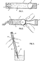
- Figure 1 shows a filled dispenser in longitudinal section
- Figure 2 shows the same tube being manipulated to expell its contents
- Figure 3 shows a pipette being manipulated to suck-up a liquid.
- this embodiment of the dispenser comprises a flexible cylindrical tube 1.
- the tube may be of flexible elastic plastics material, for example low density polyethylene or plasticized P.V.C.
- the material must of course be selected to be compatible with the contents of the tube.
- a nozzle member 2 At one end of the tube 1 is a nozzle member 2 having a cap 3 over the nozzle.
- the tube 1 is filled with a pasty material 4 such as toothpaste and at the end opposite to the nozzle contains a piston in the form of a ball 5 with a plug 6 preventing accidental loss of the ball from the tube.
- the ball 5 may for example be of plastics e.g. polystyrene, or nylon, glass or steel.
- the plug 6 has a through-bore which allows air to enter the tube behind the ball, so that manipulation of the ball within the tube is not hindered by the formation of a vacuum between the ball 5 and the plug 6.
- the cap 3 is removed and manual pressure is applied to the tube 1 by squeezing the tube adjacent the ball 5 and between the ball 5 and plug 6. This forces the ball 5 towards the nozzle member 2, so that the ball acts as a piston and expells some of the contents 4 through the nozzle.
- the manual pressure is removed the ball remains in its new position still in contact with the contents, and even if the flexible tube has a resilience which returns the walls to their original position, the position of the ball can easily be seen where it is gripped by the flexible tube and this gives a visual indication of the amount of the contents remaining in the tube.
- substantially all the contents can be expelled, especially if the rear end of the nozzle is shaped to be complementary to the piston.
- the dispenser of the present invention may be used with a very wide range of liquid, semi liquid or pasty contents.
- the dimensions of the tube, piston and nozzle may be varied to suit any desired discharge amount of the contents.
- an extension nozzle may be provided to fit over the normal nozzle, or the nozzle member can be formed initially with an elongate nozzle.
- the simplicity of the component parts of the dispenser means that the ⁇ components can be manufactured and assembled economically, and the dispenser can be filled with its contents without any of the complex machinery conventionally associated with collapsible tubes.
- an evacuator of the invention is shown as a pipette based on a flexible elastic tube 11 which may be of transparent plastics and marked with graduations.
- One end of the tube is closed with a tapering nozzle 12 and the other end is closed with a perforated plug 16.
- a ball 15 of diameter slightly larger than the tube 11 is positioned within the tube so as to slightly distend the walls of the tube, so that the ball is gripped by the tube but is movable within the tube by manual pressure.
- the ball By squeezing the tube adjacent the ball and on the nozzle side of the ball, the ball may be moved towards the plug to suck up liquid 14 into the tube when the nozzle is placed in a beaker of the liquid.
- the liquid may be dispensed from the tube by manipulating the ball in the opposite direction as described with respect to Figure 2.
- the most important aspect of the invention is the .ability to displace the tube's contents, by externally operating the ball, either positively by exerting pressure, or negatively by creating vacuum.
- the former is directly applicable to dispensing the contents of the tube, which in this case has a role of a container, fitted with a nozzle appropriate for the handled medium, and the intended purpose.
- the latter can be used for withdrawals, and would be applicable to pipettes, syringes, syphons, samplers, and generally to evacuators of all kinds.
- a dispenser or evacuator for a particular application, development work should be - in the first instance - directed towards finding the most "universal" container material, preferably a co-extruded laminate, which combines the necessary mechanical properties with chemical inertness of the contact surface (e.g. a suitable elastomer, or a thin layer of a closed cell foam for "cushioning" the ball) ensuring toxicological 'acceptance,'impermeability, good slip, acceptable costs, aesthetic appearance, etc.
- the propelling balls can be solid (especially when the dimensions are small) or hollow e.g.
- a conventional plastic tube is in many respects an inadequate container. Its production is by no means cheap, with the necessity of inside and outside lacquering, tricky marrying by spin welding of an extruded tube with a moulded shoulder, and above all, the necessity of sealing the end of tube, which is a troublesome, costly (energy, and time consuming) operation, requiring constant vigilance, and.beset with a high rate of rejects, and failures in production, and after.
- For a consumer dispensing becomes increasingly difficult with time the user never knows at any one time how much product there is left in the tube, and is never able to use all its contents.
- the habitual "sucking-back" of the contents while dispensing is a source of annoyance, and of harmful microbial contamination.
- Its other disadvantage is the "fishtail" aspect of the sealed tube, which causes difficulties in packaging, and storage,
- assembly of the dispenser of the present invention requires no use of power: (heating), and the existing filling machines can be easily adapted for assembly at the present heating and sealing stations.
- the familiar "fishtail” seal is replaced by a "push fit” base, housing a propelling ball of a suitable size, and material.
- Aesthetics are improved, and storage facilitated because of the upright packing and standing.
- the consumer is able to avail him/herself of practically the full contents of the tube, dispensed easily, with no suck-back, by one hand operation, while leaving the other hand free to perform additional actions, like, for instance, in applying shampoo.
- There is also the ability to use such a container as a metering device and there is a well defined indication of the quantity of the product still remaining in the container due to the , distension pf the tube by the ball.
- the dispenser of the invention is equally advantageous when compared with a metal collapsible tube. Even the cheapest variety, the aluminium tube, is rapidly increasing in price. Furthermore, aluminium, being a base metal requires internal coating to ensure compatibility with the packaged media; a costly and by no means foolproof operation. There are also other disadvantages, like the tube's vulnerability to an unsightly damage by bruising, which is no problem in a tube of a suitable laminate, fitted with a ball piston.
- a teat can be cheaply, and conveniently replaced by a piece of tubing containing a ball piston.
Landscapes
- Engineering & Computer Science (AREA)
- Mechanical Engineering (AREA)
- Closures For Containers (AREA)
- Containers And Packaging Bodies Having A Special Means To Remove Contents (AREA)
- Tubes (AREA)
Priority Applications (1)
| Application Number | Priority Date | Filing Date | Title |
|---|---|---|---|
| EP81302314A EP0066016A1 (fr) | 1981-05-26 | 1981-05-26 | Appareil pour la distribution et l'évacuation |
Applications Claiming Priority (1)
| Application Number | Priority Date | Filing Date | Title |
|---|---|---|---|
| EP81302314A EP0066016A1 (fr) | 1981-05-26 | 1981-05-26 | Appareil pour la distribution et l'évacuation |
Publications (1)
| Publication Number | Publication Date |
|---|---|
| EP0066016A1 true EP0066016A1 (fr) | 1982-12-08 |
Family
ID=8188314
Family Applications (1)
| Application Number | Title | Priority Date | Filing Date |
|---|---|---|---|
| EP81302314A Withdrawn EP0066016A1 (fr) | 1981-05-26 | 1981-05-26 | Appareil pour la distribution et l'évacuation |
Country Status (1)
| Country | Link |
|---|---|
| EP (1) | EP0066016A1 (fr) |
Cited By (4)
| Publication number | Priority date | Publication date | Assignee | Title |
|---|---|---|---|---|
| WO2011068892A3 (fr) * | 2009-12-01 | 2011-10-20 | Amanda Pascatore | Dispositif de stockage et de distribution de fluides |
| CN103281928A (zh) * | 2010-12-02 | 2013-09-04 | 高爽工业公司 | 可佩戴分配器 |
| WO2017077458A1 (fr) * | 2015-11-03 | 2017-05-11 | Bantjes Neville Don | Distributeur à porter sur la personne |
| WO2020048918A1 (fr) * | 2018-09-03 | 2020-03-12 | Rigshospitalet | Dispositif de distribution de médicament |
Citations (3)
| Publication number | Priority date | Publication date | Assignee | Title |
|---|---|---|---|---|
| CH459875A (de) * | 1966-07-04 | 1968-07-15 | Ciba Geigy | Dosiertube |
| US3521795A (en) * | 1968-03-04 | 1970-07-28 | Bahl Associates | Full discharge dispensing container |
| US3698561A (en) * | 1971-05-12 | 1972-10-17 | Warner Lambert Co | Filtering pipette |
-
1981
- 1981-05-26 EP EP81302314A patent/EP0066016A1/fr not_active Withdrawn
Patent Citations (3)
| Publication number | Priority date | Publication date | Assignee | Title |
|---|---|---|---|---|
| CH459875A (de) * | 1966-07-04 | 1968-07-15 | Ciba Geigy | Dosiertube |
| US3521795A (en) * | 1968-03-04 | 1970-07-28 | Bahl Associates | Full discharge dispensing container |
| US3698561A (en) * | 1971-05-12 | 1972-10-17 | Warner Lambert Co | Filtering pipette |
Cited By (5)
| Publication number | Priority date | Publication date | Assignee | Title |
|---|---|---|---|---|
| WO2011068892A3 (fr) * | 2009-12-01 | 2011-10-20 | Amanda Pascatore | Dispositif de stockage et de distribution de fluides |
| US8708194B2 (en) | 2009-12-01 | 2014-04-29 | Amanda R. PASCATORE | Dispenser with movable dispensing component anchored by a filament |
| CN103281928A (zh) * | 2010-12-02 | 2013-09-04 | 高爽工业公司 | 可佩戴分配器 |
| WO2017077458A1 (fr) * | 2015-11-03 | 2017-05-11 | Bantjes Neville Don | Distributeur à porter sur la personne |
| WO2020048918A1 (fr) * | 2018-09-03 | 2020-03-12 | Rigshospitalet | Dispositif de distribution de médicament |
Similar Documents
| Publication | Publication Date | Title |
|---|---|---|
| US8511924B2 (en) | Dispensing device for viscous materials | |
| EP1546021B1 (fr) | Ensemble recipient et valve pour stocker et distribuer des substances, et procede associe | |
| US3777949A (en) | Improved single dose disposable container and accessories | |
| US5048727A (en) | Preassembled unit dose dispenser having a compressible container and a tube prefilled with a unit dose of opthalmic gel. | |
| US10858170B2 (en) | Dual dispensing cosmetic container | |
| US4013073A (en) | Dispensing device | |
| US3493147A (en) | Collapsible tube and follower | |
| US20120282010A1 (en) | Liquid, fluid, and lotion container and applicator | |
| NZ255383A (en) | Pliable tubular container; depressable walls with stopper at one end and dispensing nozzle at other end | |
| US4776494A (en) | Unit dose dispensing collapsible tube adapted to dispense a viscious liquid therefrom | |
| US11910904B2 (en) | Pen applicator system for applying a cosmetic product | |
| CN100386247C (zh) | 用于储存和分配物质的容器及阀组件,以及相关方法 | |
| US6964357B2 (en) | Stable upright fluid dispensing containers | |
| EP0066016A1 (fr) | Appareil pour la distribution et l'évacuation | |
| GB2062767A (en) | Dispensing or Evacuating Device | |
| US5346108A (en) | Gaged dispensing apparatus | |
| US20230270235A1 (en) | Applicator system for applying a cosmetic product | |
| US12139307B2 (en) | Container comprising a duckbill valve and a leak-resistant closure mechanism | |
| US20070210113A1 (en) | Dispensing Container | |
| US11279548B1 (en) | Dispenser tube | |
| US20080029552A1 (en) | Dispensing container for flowable materials | |
| GB2203345A (en) | Dispenser for vaginal creams | |
| JPH0632380A (ja) | 高粘度の粘性物押出し容器 | |
| EP0928282A1 (fr) | Distributeur de liquide |
Legal Events
| Date | Code | Title | Description |
|---|---|---|---|
| PUAI | Public reference made under article 153(3) epc to a published international application that has entered the european phase |
Free format text: ORIGINAL CODE: 0009012 |
|
| AK | Designated contracting states |
Designated state(s): AT BE CH DE FR IT LU NL SE |
|
| STAA | Information on the status of an ep patent application or granted ep patent |
Free format text: STATUS: THE APPLICATION IS DEEMED TO BE WITHDRAWN |
|
| 18D | Application deemed to be withdrawn |
Effective date: 19831114 |