EP0068087B1 - Boatless evaporation method - Google Patents
Boatless evaporation method Download PDFInfo
- Publication number
- EP0068087B1 EP0068087B1 EP82102981A EP82102981A EP0068087B1 EP 0068087 B1 EP0068087 B1 EP 0068087B1 EP 82102981 A EP82102981 A EP 82102981A EP 82102981 A EP82102981 A EP 82102981A EP 0068087 B1 EP0068087 B1 EP 0068087B1
- Authority
- EP
- European Patent Office
- Prior art keywords
- metal
- wire
- heating
- boatless
- supply
- Prior art date
- Legal status (The legal status is an assumption and is not a legal conclusion. Google has not performed a legal analysis and makes no representation as to the accuracy of the status listed.)
- Expired
Links
- 238000001704 evaporation Methods 0.000 title claims description 8
- 229910052751 metal Inorganic materials 0.000 claims description 18
- 239000002184 metal Substances 0.000 claims description 18
- 238000000034 method Methods 0.000 claims description 15
- 238000010438 heat treatment Methods 0.000 claims description 14
- RTAQQCXQSZGOHL-UHFFFAOYSA-N Titanium Chemical compound [Ti] RTAQQCXQSZGOHL-UHFFFAOYSA-N 0.000 claims description 7
- VYZAMTAEIAYCRO-UHFFFAOYSA-N Chromium Chemical compound [Cr] VYZAMTAEIAYCRO-UHFFFAOYSA-N 0.000 claims description 6
- 229910052804 chromium Inorganic materials 0.000 claims description 6
- 239000011651 chromium Substances 0.000 claims description 6
- 230000008020 evaporation Effects 0.000 claims description 6
- 229910052719 titanium Inorganic materials 0.000 claims description 6
- 239000010936 titanium Substances 0.000 claims description 6
- 230000005499 meniscus Effects 0.000 claims description 5
- 238000000151 deposition Methods 0.000 claims description 3
- 239000007787 solid Substances 0.000 claims description 3
- 239000000463 material Substances 0.000 description 7
- 238000007740 vapor deposition Methods 0.000 description 7
- 238000010894 electron beam technology Methods 0.000 description 3
- 150000002739 metals Chemical class 0.000 description 3
- RYGMFSIKBFXOCR-UHFFFAOYSA-N Copper Chemical compound [Cu] RYGMFSIKBFXOCR-UHFFFAOYSA-N 0.000 description 2
- 229910052782 aluminium Inorganic materials 0.000 description 2
- XAGFODPZIPBFFR-UHFFFAOYSA-N aluminium Chemical compound [Al] XAGFODPZIPBFFR-UHFFFAOYSA-N 0.000 description 2
- 229910052802 copper Inorganic materials 0.000 description 2
- 239000010949 copper Substances 0.000 description 2
- 239000004065 semiconductor Substances 0.000 description 2
- 239000000758 substrate Substances 0.000 description 2
- 229910052715 tantalum Inorganic materials 0.000 description 2
- GUVRBAGPIYLISA-UHFFFAOYSA-N tantalum atom Chemical compound [Ta] GUVRBAGPIYLISA-UHFFFAOYSA-N 0.000 description 2
- WFKWXMTUELFFGS-UHFFFAOYSA-N tungsten Chemical compound [W] WFKWXMTUELFFGS-UHFFFAOYSA-N 0.000 description 2
- 229910052721 tungsten Inorganic materials 0.000 description 2
- 239000010937 tungsten Substances 0.000 description 2
- XLYOFNOQVPJJNP-UHFFFAOYSA-N water Substances O XLYOFNOQVPJJNP-UHFFFAOYSA-N 0.000 description 2
- ZOXJGFHDIHLPTG-UHFFFAOYSA-N Boron Chemical compound [B] ZOXJGFHDIHLPTG-UHFFFAOYSA-N 0.000 description 1
- ZOKXTWBITQBERF-UHFFFAOYSA-N Molybdenum Chemical compound [Mo] ZOKXTWBITQBERF-UHFFFAOYSA-N 0.000 description 1
- BQCADISMDOOEFD-UHFFFAOYSA-N Silver Chemical compound [Ag] BQCADISMDOOEFD-UHFFFAOYSA-N 0.000 description 1
- PNEYBMLMFCGWSK-UHFFFAOYSA-N aluminium oxide Inorganic materials [O-2].[O-2].[O-2].[Al+3].[Al+3] PNEYBMLMFCGWSK-UHFFFAOYSA-N 0.000 description 1
- 230000015572 biosynthetic process Effects 0.000 description 1
- 229910052796 boron Inorganic materials 0.000 description 1
- 239000011248 coating agent Substances 0.000 description 1
- 238000000576 coating method Methods 0.000 description 1
- 238000011109 contamination Methods 0.000 description 1
- 229910052593 corundum Inorganic materials 0.000 description 1
- PCHJSUWPFVWCPO-UHFFFAOYSA-N gold Chemical compound [Au] PCHJSUWPFVWCPO-UHFFFAOYSA-N 0.000 description 1
- 229910052737 gold Inorganic materials 0.000 description 1
- 239000010931 gold Substances 0.000 description 1
- PQTCMBYFWMFIGM-UHFFFAOYSA-N gold silver Chemical compound [Ag].[Au] PQTCMBYFWMFIGM-UHFFFAOYSA-N 0.000 description 1
- 229910002804 graphite Inorganic materials 0.000 description 1
- 239000010439 graphite Substances 0.000 description 1
- 230000001939 inductive effect Effects 0.000 description 1
- 229910052750 molybdenum Inorganic materials 0.000 description 1
- 239000011733 molybdenum Substances 0.000 description 1
- MGRWKWACZDFZJT-UHFFFAOYSA-N molybdenum tungsten Chemical compound [Mo].[W] MGRWKWACZDFZJT-UHFFFAOYSA-N 0.000 description 1
- 230000000135 prohibitive effect Effects 0.000 description 1
- 229910052709 silver Inorganic materials 0.000 description 1
- 239000004332 silver Substances 0.000 description 1
- 238000005019 vapor deposition process Methods 0.000 description 1
- 235000012431 wafers Nutrition 0.000 description 1
- 229910001845 yogo sapphire Inorganic materials 0.000 description 1
Images

Classifications
-
- C—CHEMISTRY; METALLURGY
- C23—COATING METALLIC MATERIAL; COATING MATERIAL WITH METALLIC MATERIAL; CHEMICAL SURFACE TREATMENT; DIFFUSION TREATMENT OF METALLIC MATERIAL; COATING BY VACUUM EVAPORATION, BY SPUTTERING, BY ION IMPLANTATION OR BY CHEMICAL VAPOUR DEPOSITION, IN GENERAL; INHIBITING CORROSION OF METALLIC MATERIAL OR INCRUSTATION IN GENERAL
- C23C—COATING METALLIC MATERIAL; COATING MATERIAL WITH METALLIC MATERIAL; SURFACE TREATMENT OF METALLIC MATERIAL BY DIFFUSION INTO THE SURFACE, BY CHEMICAL CONVERSION OR SUBSTITUTION; COATING BY VACUUM EVAPORATION, BY SPUTTERING, BY ION IMPLANTATION OR BY CHEMICAL VAPOUR DEPOSITION, IN GENERAL
- C23C14/00—Coating by vacuum evaporation, by sputtering or by ion implantation of the coating forming material
- C23C14/22—Coating by vacuum evaporation, by sputtering or by ion implantation of the coating forming material characterised by the process of coating
- C23C14/24—Vacuum evaporation
Definitions
- the invention relates to a method of boatless vapor depositing a metal onto a workpiece in a vacuum chamber, where the top of a solid supply of said metal being aligned with said workpiece is melted by heating without electron bombardment and where said metal is evaporated from said melt.
- Reactive metals such as titanium, chromium and the like are frequently used in semiconductor devices and may be deposited by a vapor deposition process.
- Vapor deposition methods are described in van Amstel US patent 3 499 785, Donckel US patent 3 860 444 and Anderson US patent 4 061 800. These processes employ crucibles or boats of tantalum, tungsten-molybdenum, boron nitride-graphite or TiB 2 -Al 2 O 3 . These crucibles react with certain reactive metals such as chromium and titanium. Tungsten crucibles not only yield films containing traces of tungsten but they also only last for one or two runs before they fail.
- the invention intends to overcome the disadvantages discussed above.
- the end of the wire is radiantly heated to form a molten spherical meniscus thereon which serves as the coating source for the substrates.
- the wire may be chromium, titanium, aluminum, gold silver, copper and the like.
- This vapor deposition method has a number of disadvantages over the prior art vapor deposition methods.
- One advantage is that there is no contamination of the deposited metal such as is common when crucibles or boats are used.
- Another advantage over the electron beam gun evaporation process is that there are no charge level problems caused by scattered electrons which build up on the workpiece.
- a feed mechanism 10 provides a metal wire 12 to move vertically so that the end 13 thereof may be heated by a heating means 14.
- a top view of a heater 14 is shown in Figure 2 where a resistance coil 15 surrounds the top 13 of the metal wire or rod 12.
- a side view of the resistance coil 15 and the wire 12 is shown in Figure 3.
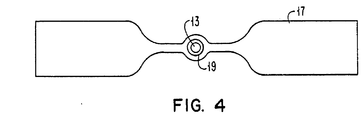
- the resistance coil 15 may also be in the form of a filament resistance strip 17 having an annular ring portion 19 surrounding the wire top 13 as shown in Figure 4.
- the metal wire or rod 12 is preferably chromium, titanium or aluminum, although other metals such as gold, silver, copper, tantalum and molybdenum may be used.
- spherical platform 18 may be rotated by motor 20 and detached therefrom by means of decoupler 22.
- the wire 12 and the substrates 16 are arranged in a closed vacuum chamber 23 so that the workpieces 16 are facing the top 13 of the wire 12 and within the vaporcloud cone 24 formed by the evaporation.
- the pressure in the chamber ranges from 1,333. 10- 5 to 1,333.10-8 mbar with the preferred range for chromium and titanium being 1,333 10'6 to 1,333 10-1 mbar.
- the heater 14 is activated to heat the end 13 of the wire 12 so that the metal is melted to form a molten spherical meniscus.
- the end 13 becomes molten, it finds its lowest energy formation, becomes spherical and stays on the wire. Enough heat is applied without increasing the molten mass so that the evaporation occurs from the spherical molten mass 13.
- any extraneous radiant heat generated by resistance heating can be minimized by using a water cooled shield (not shown).
- the addition of water cooled parabolic reflectors (not shown) about the wire end 13 focuses the radiant heat on the molten sphere 13.
Landscapes
- Chemical & Material Sciences (AREA)
- Chemical Kinetics & Catalysis (AREA)
- Engineering & Computer Science (AREA)
- Materials Engineering (AREA)
- Mechanical Engineering (AREA)
- Metallurgy (AREA)
- Organic Chemistry (AREA)
- Physical Vapour Deposition (AREA)
- Physical Deposition Of Substances That Are Components Of Semiconductor Devices (AREA)
Description
- The invention relates to a method of boatless vapor depositing a metal onto a workpiece in a vacuum chamber, where the top of a solid supply of said metal being aligned with said workpiece is melted by heating without electron bombardment and where said metal is evaporated from said melt.
- Reactive metals such as titanium, chromium and the like are frequently used in semiconductor devices and may be deposited by a vapor deposition process. Vapor deposition methods are described in van Amstel US patent 3 499 785, Donckel US patent 3 860 444 and Anderson US patent 4 061 800. These processes employ crucibles or boats of tantalum, tungsten-molybdenum, boron nitride-graphite or TiB2-Al2O3. These crucibles react with certain reactive metals such as chromium and titanium. Tungsten crucibles not only yield films containing traces of tungsten but they also only last for one or two runs before they fail.
- In addition, the crucibles or boats need to be refilled periodically and with the advent of the high productivity load lock tool, boat or filament frequent changes become prohibitive.
- Another approach described in the IBM Technical Disclosure Bulletin, Vol. 18, No. 10, March 1976, p. 3413, has been to use a rod of the material to be evaporated and to heat the material with an electron beam to create a molten pool at the top of the rod for vapor deposition. This method has not been suitable, in general, because of charge level problems. Electron beam heating for vapor depositions causes spurious reflected electrons to be included in the deposited films. This in turn gives the film a higher energy or charge level which is undesirable in a film used for a memory device. The charge level causes errors in the memory device during normal computer operation.
- The invention intends to overcome the disadvantages discussed above.
- In principle vapor deposition evaporating the end of a wire or rod made of that same material is used. The end of the wire is radiantly heated to form a molten spherical meniscus thereon which serves as the coating source for the substrates. The wire may be chromium, titanium, aluminum, gold silver, copper and the like.
- This vapor deposition method has a number of disadvantages over the prior art vapor deposition methods. One advantage is that there is no contamination of the deposited metal such as is common when crucibles or boats are used. Another advantage over the electron beam gun evaporation process is that there are no charge level problems caused by scattered electrons which build up on the workpiece. In addition, it is not necessary to break open a closed chamber and replace a boat or filament because the feed mechanism will feed the wire as required for an extended period of time.
- In the earlier European patent application 0 055 344 (state of the art within the meaning of Art 54 (3) EPC), a method and apparatus are disclosed for boatless vapor depositing a material onto a workpiece being substantially in line with the top of a wire of said material, where the top of said wire is melted by heating inductively, where said melted material is evaporated and where the evaporated material is replaced by advancing the wire at a controlled rate into the effective range of the inductive heating means.
- Objects and features of the invention will be apparent from the following description in which the preferred embodiments are set forth in detail in conjunction with the accompanying drawings, wherein:
- Figure 1 is a schematic view of the apparatus used in the vapor deposition method according to the invention.
- Figure 2 is a top view of a heating coil and wire embodiment of Figure 1.
- Figure 3 is a side view of a heating coil and wire embodiment of Figure 1.
- Figure 4 is a top view of a resistance heating strip and wire embodiment of Figure 1.
- As shown in Figure 1, a
feed mechanism 10 provides ametal wire 12 to move vertically so that theend 13 thereof may be heated by a heating means 14. A top view of aheater 14 is shown in Figure 2 where aresistance coil 15 surrounds thetop 13 of the metal wire orrod 12. A side view of theresistance coil 15 and thewire 12 is shown in Figure 3. Theresistance coil 15 may also be in the form of afilament resistance strip 17 having anannular ring portion 19 surrounding thewire top 13 as shown in Figure 4. - The metal wire or
rod 12 is preferably chromium, titanium or aluminum, although other metals such as gold, silver, copper, tantalum and molybdenum may be used. - Workpieces such as
semiconductor wafers 16 are placed onspherical platform 18. Thespherical platform 18 may be rotated bymotor 20 and detached therefrom by means ofdecoupler 22. - The
wire 12 and thesubstrates 16 are arranged in a closedvacuum chamber 23 so that theworkpieces 16 are facing thetop 13 of thewire 12 and within thevaporcloud cone 24 formed by the evaporation. The pressure in the chamber ranges from 1,333. 10-5 to 1,333.10-8 mbar with the preferred range for chromium and titanium being 1,333 10'6 to 1,333 10-1 mbar. - The
heater 14 is activated to heat theend 13 of thewire 12 so that the metal is melted to form a molten spherical meniscus. When theend 13 becomes molten, it finds its lowest energy formation, becomes spherical and stays on the wire. Enough heat is applied without increasing the molten mass so that the evaporation occurs from the sphericalmolten mass 13. One can control both the rate of evaporation from thesphere 13 and thesphere 13 size with a constant heat source by controlling the rate of feeding thewire 12 into the heat zone. - Any extraneous radiant heat generated by resistance heating can be minimized by using a water cooled shield (not shown). The addition of water cooled parabolic reflectors (not shown) about the
wire end 13 focuses the radiant heat on themolten sphere 13. - The process with a resistance strip heater using titanium wire of 15.24 mm (0.6 inch) diameter gave an evaporation rate of 0.05 nm (0.5 Å) per second at a distance of 406 mm (16 inches).
Claims (5)
Applications Claiming Priority (2)
| Application Number | Priority Date | Filing Date | Title |
|---|---|---|---|
| US278932 | 1981-06-30 | ||
| US06/278,932 US4390571A (en) | 1981-06-30 | 1981-06-30 | Boatless point source evaporation method |
Publications (2)
| Publication Number | Publication Date |
|---|---|
| EP0068087A1 EP0068087A1 (en) | 1983-01-05 |
| EP0068087B1 true EP0068087B1 (en) | 1986-10-15 |
Family
ID=23067001
Family Applications (1)
| Application Number | Title | Priority Date | Filing Date |
|---|---|---|---|
| EP82102981A Expired EP0068087B1 (en) | 1981-06-30 | 1982-04-07 | Boatless evaporation method |
Country Status (4)
| Country | Link |
|---|---|
| US (1) | US4390571A (en) |
| EP (1) | EP0068087B1 (en) |
| JP (1) | JPS6037869B2 (en) |
| DE (1) | DE3273808D1 (en) |
Families Citing this family (7)
| Publication number | Priority date | Publication date | Assignee | Title |
|---|---|---|---|---|
| US4508612A (en) * | 1984-03-07 | 1985-04-02 | International Business Machines Corporation | Shield for improved magnetron sputter deposition into surface recesses |
| DE3530106A1 (en) * | 1985-08-23 | 1987-02-26 | Kempten Elektroschmelz Gmbh | VAPORIZATION MATERIAL FOR VAPORIZING INORGANIC COMPOUNDS BY MEANS OF A PHOTON-GENERATING RADIATION HEATING SOURCE IN CONTINUOUSLY OPERATED VACUUM VACUUM DEVICES |
| JPH0676607B2 (en) * | 1986-09-02 | 1994-09-28 | 三井東圧化学株式会社 | Method for producing ferromagnetic metal powder |
| JP2005091345A (en) * | 2003-08-13 | 2005-04-07 | Fuji Photo Film Co Ltd | Method and device for producing vapor-deposition type phosphor sheet, and vapor deposition type phosphor sheet |
| CN103993266B (en) * | 2014-04-17 | 2016-07-06 | 京东方科技集团股份有限公司 | Vacuum evaporation equipment |
| JP6488928B2 (en) * | 2015-07-15 | 2019-03-27 | アイシン精機株式会社 | Vapor deposition equipment |
| KR20200105835A (en) | 2017-12-06 | 2020-09-09 | 애리조나 씬 필름 리서치 엘엘씨 | System and method for additive manufacturing for deposition of metal and ceramic materials |
Citations (1)
| Publication number | Priority date | Publication date | Assignee | Title |
|---|---|---|---|---|
| EP0055344A1 (en) * | 1980-12-29 | 1982-07-07 | Rockwell International Corporation | Inductive heating arrangement for evaporating a thin alloy film onto a substrate, and method therefor |
Family Cites Families (7)
| Publication number | Priority date | Publication date | Assignee | Title |
|---|---|---|---|---|
| NL6600179A (en) * | 1966-01-07 | 1967-07-10 | ||
| BE795116A (en) * | 1972-02-08 | 1973-05-29 | Cockerill | EVAPORATION BATH FEEDING PROCESS |
| US4061800A (en) * | 1975-02-06 | 1977-12-06 | Applied Materials, Inc. | Vapor desposition method |
| US4183975A (en) * | 1978-03-16 | 1980-01-15 | Dare Pafco, Inc. | Vacuum metallizing process |
| US4276855A (en) * | 1979-05-02 | 1981-07-07 | Optical Coating Laboratory, Inc. | Coating apparatus |
| JPS5512100A (en) * | 1979-07-09 | 1980-01-28 | Shichifuku Shiyokuhin Kk | Egg tofu sealed container |
| US4263872A (en) * | 1980-01-31 | 1981-04-28 | Rca Corporation | Radiation heated reactor for chemical vapor deposition on substrates |
-
1981
- 1981-06-30 US US06/278,932 patent/US4390571A/en not_active Expired - Lifetime
-
1982
- 1982-04-07 EP EP82102981A patent/EP0068087B1/en not_active Expired
- 1982-04-07 DE DE8282102981T patent/DE3273808D1/en not_active Expired
- 1982-04-16 JP JP57062664A patent/JPS6037869B2/en not_active Expired
Patent Citations (1)
| Publication number | Priority date | Publication date | Assignee | Title |
|---|---|---|---|---|
| EP0055344A1 (en) * | 1980-12-29 | 1982-07-07 | Rockwell International Corporation | Inductive heating arrangement for evaporating a thin alloy film onto a substrate, and method therefor |
Also Published As
| Publication number | Publication date |
|---|---|
| JPS583971A (en) | 1983-01-10 |
| JPS6037869B2 (en) | 1985-08-28 |
| EP0068087A1 (en) | 1983-01-05 |
| DE3273808D1 (en) | 1986-11-20 |
| US4390571A (en) | 1983-06-28 |
Similar Documents
| Publication | Publication Date | Title |
|---|---|---|
| US4505948A (en) | Method of coating ceramics and quartz crucibles with material electrically transformed into a vapor phase | |
| US4871434A (en) | Process for equipment to coat tools for machining and forming techniques with mechanically resistant layers | |
| US2423729A (en) | Vaporization of substances in a vacuum | |
| US5296274A (en) | Method of producing carbon-containing materials by electron beam vacuum evaporation of graphite and subsequent condensation | |
| US4412899A (en) | Cubic boron nitride preparation utilizing nitrogen gas | |
| EP0041395B1 (en) | Cubic boron nitride preparation | |
| US2413606A (en) | Method of coating by evaporating metals | |
| EP0068087B1 (en) | Boatless evaporation method | |
| GB1133936A (en) | Method and apparatus for forming tenacious deposits on a surface | |
| US5849371A (en) | Laser and laser-assisted free electron beam deposition apparatus and method | |
| EP0308658B1 (en) | Apparatus and method for evaporating metallic films | |
| US2902574A (en) | Source for vapor deposition | |
| CA2476855C (en) | Method and device for coating a substrate | |
| EP0055344A1 (en) | Inductive heating arrangement for evaporating a thin alloy film onto a substrate, and method therefor | |
| EP0010971B1 (en) | Deposition process | |
| US2450856A (en) | Method of coating by evaporating metals | |
| US4876114A (en) | Process for the self fractionation deposition of a metallic layer on a workpiece | |
| WO1993024663A1 (en) | Apparatus and method for producing carbide coatings | |
| US2450850A (en) | Method of coating by evaporating metals | |
| US4198449A (en) | Method for the preparation of thin films of high-temperature-resistant metals such as tungsten, molybdenum, rhenium or osmium | |
| Mattox | Vacuum Deposition, Reactive Evaporation, and Gas Evaporation | |
| US4368689A (en) | Beam source for deposition of thin film alloys | |
| JPH06173004A (en) | Raw material feeder in continuous vacuum-deposition plating | |
| US2450855A (en) | Method of coating by evaporating metals | |
| Craswell | An apparatus for use in coating a body with an evaporant |
Legal Events
| Date | Code | Title | Description |
|---|---|---|---|
| PUAI | Public reference made under article 153(3) epc to a published international application that has entered the european phase |
Free format text: ORIGINAL CODE: 0009012 |
|
| AK | Designated contracting states |
Designated state(s): DE FR GB |
|
| 17P | Request for examination filed |
Effective date: 19830420 |
|
| GRAA | (expected) grant |
Free format text: ORIGINAL CODE: 0009210 |
|
| AK | Designated contracting states |
Kind code of ref document: B1 Designated state(s): DE FR GB |
|
| REF | Corresponds to: |
Ref document number: 3273808 Country of ref document: DE Date of ref document: 19861120 |
|
| ET | Fr: translation filed | ||
| PLBE | No opposition filed within time limit |
Free format text: ORIGINAL CODE: 0009261 |
|
| STAA | Information on the status of an ep patent application or granted ep patent |
Free format text: STATUS: NO OPPOSITION FILED WITHIN TIME LIMIT |
|
| 26N | No opposition filed | ||
| PGFP | Annual fee paid to national office [announced via postgrant information from national office to epo] |
Ref country code: FR Payment date: 19920226 Year of fee payment: 11 |
|
| PGFP | Annual fee paid to national office [announced via postgrant information from national office to epo] |
Ref country code: GB Payment date: 19920304 Year of fee payment: 11 |
|
| PGFP | Annual fee paid to national office [announced via postgrant information from national office to epo] |
Ref country code: DE Payment date: 19920504 Year of fee payment: 11 |
|
| PG25 | Lapsed in a contracting state [announced via postgrant information from national office to epo] |
Ref country code: GB Effective date: 19930407 |
|
| GBPC | Gb: european patent ceased through non-payment of renewal fee |
Effective date: 19930407 |
|
| PG25 | Lapsed in a contracting state [announced via postgrant information from national office to epo] |
Ref country code: FR Effective date: 19931229 |
|
| PG25 | Lapsed in a contracting state [announced via postgrant information from national office to epo] |
Ref country code: DE Effective date: 19940101 |
|
| REG | Reference to a national code |
Ref country code: FR Ref legal event code: ST |