EP0068765B1 - Verfahren zur numerischen Steuerung - Google Patents
Verfahren zur numerischen Steuerung Download PDFInfo
- Publication number
- EP0068765B1 EP0068765B1 EP82303199A EP82303199A EP0068765B1 EP 0068765 B1 EP0068765 B1 EP 0068765B1 EP 82303199 A EP82303199 A EP 82303199A EP 82303199 A EP82303199 A EP 82303199A EP 0068765 B1 EP0068765 B1 EP 0068765B1
- Authority
- EP
- European Patent Office
- Prior art keywords
- block
- data
- distance
- straight line
- holds
- Prior art date
- Legal status (The legal status is an assumption and is not a legal conclusion. Google has not performed a legal analysis and makes no representation as to the accuracy of the status listed.)
- Expired
Links
Images


Classifications
-
- G—PHYSICS
- G05—CONTROLLING; REGULATING
- G05B—CONTROL OR REGULATING SYSTEMS IN GENERAL; FUNCTIONAL ELEMENTS OF SUCH SYSTEMS; MONITORING OR TESTING ARRANGEMENTS FOR SUCH SYSTEMS OR ELEMENTS
- G05B19/00—Program-control systems
- G05B19/02—Program-control systems electric
- G05B19/18—Numerical control [NC], i.e. automatically operating machines, in particular machine tools, e.g. in a manufacturing environment, so as to execute positioning, movement or co-ordinated operations by means of program data in numerical form
- G05B19/41—Numerical control [NC], i.e. automatically operating machines, in particular machine tools, e.g. in a manufacturing environment, so as to execute positioning, movement or co-ordinated operations by means of program data in numerical form characterised by interpolation, e.g. the computation of intermediate points between programmed end points to define the path to be followed and the rate of travel along that path
-
- G—PHYSICS
- G05—CONTROLLING; REGULATING
- G05B—CONTROL OR REGULATING SYSTEMS IN GENERAL; FUNCTIONAL ELEMENTS OF SUCH SYSTEMS; MONITORING OR TESTING ARRANGEMENTS FOR SUCH SYSTEMS OR ELEMENTS
- G05B2219/00—Program-control systems
- G05B2219/30—Nc systems
- G05B2219/34—Director, elements to supervisory
- G05B2219/34101—Data compression, look ahead segment calculation, max segment lenght
Definitions
- This invention relates to a numerical control method and, more particularly, to a numerical control method for application to a numerical control device for prereading the numerical control data in a succeeding block during the execution of numerical control.
- Numerically controlled machine tools may rely upon interpolation systems of two kinds. One is a linear interpolation system for interpolation along two or three axes simultaneously, and the other is a circular interpolation system for interpolation in the XY, YZ and ZX planes, or in planes parallel thereto.
- USA3 806 7-13 refers to maximizing the length of straight line segments approximating a curvewhile maintaining the approximation within a defined tolerance, according to a formula, taking into account the total number of steps to be taken along the rotational axis and the radial axis of successive straight lines, and also the maximum error in steps along the radial axis between a given curve and the approximated curve.
- US ⁇ A ⁇ 4164693 concerns a method of producing relative movement of an element along a desired path with the movement being subdivided into a plurality of successive lengths with a determination being made of the number of steps for each axis that is needed to constitute each length.
- the number of steps in adjacent lengths is made to vary only within a constant amount so that the minimum and maximum lengths of each next length is determinable from its preceding length.
- US ⁇ A ⁇ 3629558 relates to a method of preparing an NC-Control record of minimum length by running a probe along a model whereon points P1...P ⁇ are scanned and memorised in a buffer memory.
- the data is optimised by examining the coordinates and identifying those points which represent a change in z-coordinate relative to a preset value. Accordingly, only those points are punched which are necessary to define the examined surface with a certain accuracy.
- a chord is defined between e.g. P o and P 2 and the shortest distance between the coordinates of P 1 (between P o and P 2 ), the chord is measured and compared with a reference value and only punched if it is larger than this value.
- prereading technique When only a very short time interval is required for movement based upon one block of data, a so-called prereading technique may be employed for reading in data in such fashion as to enhance machining efficiency. Before describing this technique, a discussion will first be had with regard to the conventional method that does not employ prereading.
- NC data is read in block-by-block, and each time machining or movement based on one block is completed, data from the next block is read in.
- a process is disclosed in the aforementioned US-A-3431 478.
- This is followed by a format check, decoding, calculation of the specified amount of movement (namely an incremental value), and by other preprocessing, after which machining or movement is controlled based upon said next block.
- processing executed by the NC device does not keep up with the action of the machine tool because of such factors as preprocessing time and the response of the motor for driving the movable element of the machine tool, such as the table.
- the attendant disadvantages are a decline in machining efficiency and a failure to attain a highly precise machined surface.
- prereading data that is written in while numerically controlled machining based on the current block is being executed.
- preprocessing based on the succeeding or second block may be performed in advance.
- movement based on the second block may therefore be executed immediately without waiting for the completion of preprocessing following movement based on the first block. The result is a more efficient machining operation.
- the present invention seeks to reduce or eliminate the aforementioned disadvantages encountered in the prior art.
- the object of the present invention is to provide a numerical control method for controlling the movement of a tool in such fashion that the length of each of a plurality of straight line segments approximating a curve is not allowed to fall below a prescribed value.
- a numerical control method in which a curve is approximated by a plurality of straight line segments, numerically controlled machining is performed on the basis of numerical control data having a positional command of one block for each straight line segment, and preprocessing is executed by prereading a positional command of a succeeding block while numericallly controlled machining based on a current block is in progress, said method comprising the steps of:
- the present invention provides a numerical control method based on computing the lengths of a plurality of straight line segments that approximate a curve, determining whether the length of each line segment is less than a preset permissible length, and inhibiting control of movement based on a line segment when its length is less than the preset length.
- the distance from the extension of said line segment to the end point of the next contiguous line segment is computed, and movement is controlled toward the end point of the contiguous line segment if the computed distance is les than a separately entered permissible distance. If not, then movement is controlled toward the starting point of the contiguous line segment.
- Numerical control data for controlling a tool in the abovementioned manner may be created in accordance with the invention to enable an ordinary numerical control device to be employed without modification thereof.
- preprocessing for a successive increment of movement may be completed while a tool or other movable member is in motion, thereby shortening machining time and preventing intermittent machine operation.
- a curved surface of a three-dimensional metal mold or the like when drawn out on the plane of a blueprint, is generally represented by a plurality of given section curves, but no data is shown for the shapes of the areas lying between the adjacent given section curves.
- a method of creating the curved surface of a three-dimensional body namely a method of creating NC data, which includes generating a plurality of intermediate sections and finding a section curve (intermediate section curve) in each of the intermediate sections, in accordance with predetermined rules, from section data specifying given sections of the three-dimensional body and from data specifying section curves in the given sections, and generating the curved surface, namely the NC data, from the plurality of generated intermediate section curves.
- a first of two given section curves is, in effect, shifted in space while being modified so as to be superimposed on-the second given section curve, thereby generating a curved surface.
- the pluraltiy of intermediate section curves when taken together, define the curved surface.
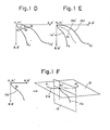
- Fig. 1 is an illustrative view useful in describing a method of creating a surface for a case where two section curves and one reference curve are given.
- Reference numerals 11, 12 denote two given sections of a three-dimensional body, and 11a, 12a denote given section curves for a case where the body is cut by the given sections 11, 12.
- Reference numeral 21 denotes a reference section containing points P 1 , P 1 ' on the respective section curves 11 a, 12a.
- Numeral 21 a denotes a reference curve lying in the reference section 21 and specifying the external form of the body.
- Numeral 13 designates an intermediate section so generated as to contain a dividing point S at which the length of the reference curve 21a is partitioned into the ratio - m:n.
- the method of creating a curved surface proceeds in the following manner.
- a permissible travelling distance to be described below is set so as to enable the smooth cutting of a surface, and a portion of the NC data is deleted so as to move the cutting tool over said permissible travelling distance, whereby the distance traversed by the tool at one time is increased.
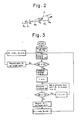
- FIG. 2 is an illustrative view useful in describing a machining method according to the present invention and showing an enlargement of an intermediate section curve.
- a processing flowchart is illustrated in Fig. 3. Reference will be had to these drawings to describe a method in accordance with the invention.
- FIG. 4 A block diagram of a circuit for practicing the method of the invention is illustrated in Fig. 4.
- Numeral 101 denotes a paper tape in which NC tape is punched.
- the paper tape 101 is read by a paper tape reader 102 for reading the data into an arithmetic circuit 103 adapted to compute the distance AD between the points R o , R 1 in Fig. 2.
- the arithmetic circuit 103 delivers a signal indicative of AD to a discriminating circuit 104 for comparing the distance AD against the preset permissible travel distance TD.
- An arithmetic circuit 105 for computing incremental values receives the output of the discriminating circuit 104 and delivers the incremental values to a pulse distributor 106.
- the arithmetic circuit 105 computes incremental values from R o to R 1 along each axis.
- the pulse distributor 106 distributes pulses on the basis of the incremental values and applies the pulses to a servo system, not shown, for transporting the tool.
- Numeral 107 denotes an arithmetic circuit for computing the straight line S (Fig. 2) when the condition AD ⁇ TD holds.
- An arithmetic circuit 108 receives the output of the circuit 107 and computes the distance AW from the point R to the straight line S.
- a discriminating circuit 109 receives the output AW of the discriminating circuit 107 and compares the distance AW against the preset permissible distance TW.
- the incremental value computing arithmetic circuit 105 taking the point R i-1 as the target position, computes incremental values from R 0 to R i-1 along each axis and delivers these values to the pulse distributor 106.
- the tape reader 102 reads in the next block of NC data when AD ⁇ TD or AW ⁇ TW holds.
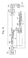
- FIG. 6 A block diagram of a circuit for creating the NC data in accordance with the present invention is illustrated in Fig. 6.
- the output of the memory 201 is connected to a read control circuit 202 for reading the NC data into an arithmetic circuit 203 which computes the distance AD between the starting point R o and end point R 1 of the straight line S 1 (Fig. 2), namely the length of the straight line S,.
- the output AD of the arithmetic circuit 203 is applied to a discriminating circuit 204 which compares the magnitude of AD against the magnitude of the preset first permissible travel distance TD.
- An NC data generating circuit 205 also receives the data read in by the read control circuit 202, as well as the output of the discriminating circuit 204.
- the output of the NC data generating circuit 205 is connected to an NC data storage memory 206.
- the NC data generating circuit 205 When the condition AD ⁇ TD holds, the NC data generating circuit 205 generates NC data specifying, in the form of an absolute command, the coordinates of the end point R 1 of the straight line S 1 , which data is stored successively in the NC data storage memory 206.
- the output of the NC data storage memory 206 is applied to an NC tape puncher 207 for punching the NC data, read successively out of the memory 206, into a paper tape 208.
- Numeral 209 denotes an arithmetic circuit for computing the straight line S 1 (Fig. 2) when the condition AD ⁇ TD holds.
- An arithmetic circuit 210 which receives the output of the circuit 209 and the data read in by the read control circuit 202, computes the distance AW from the point R, to the straight line S 1 .
- the output AW is applied to a discriminating circuit 211 which compares the magnitude of the distance AW against the preset second permissible distance TW.
- the NC data generating circuit 205 When the condition AW ⁇ TW holds, the NC data generating circuit 205 generates NC data in which the point R i-1 is the target point.
- the read control circuit 202 reads in the coordinates of the next point.
Landscapes
- Engineering & Computer Science (AREA)
- Computing Systems (AREA)
- Theoretical Computer Science (AREA)
- Human Computer Interaction (AREA)
- Manufacturing & Machinery (AREA)
- Physics & Mathematics (AREA)
- General Physics & Mathematics (AREA)
- Automation & Control Theory (AREA)
- Numerical Control (AREA)
Claims (1)
- Verfahren zur numerischen Steuerung, bei dem eine gekrümmter näherungsweise durch mehrere Geraden-Segmente bestimmt wird, ein numerisch gesteuertes Bearbeiten auf der Grundlage von numerischen Steuerdaten, die einen Positionsbefehl aus einem Block für jedes Geraden-Segment enthalten, ausgeführt wird und ein Vorverarbeiten durch Vorauslesen eines Positionsbefehls eines nachfoIgenden · Blocks durchgeführt wird, während das numerisch gesteuerte Bearbeiten auf der Grundlage eines laufenden Blocks im Gange ist, welches Verfahren folgende Schritte aufweist- Berechnen einer durch ein bewegbares Element zurückzulegenden tatsächlichen Wegstrecke AD auf der Grundlage des Positionsbefehls des nachfolgenden Blocks,-Vergleichen der Größe dieser Wegsrecke AD mit der Cröße einer getrennt eingegebenen minimal zulässigen Wegstrecke TD- Steuern der Bewegung des bewegbaren Elements auf der Grundlage des Positionsbefehls des laufenden Blocks, wenn die Bedingung AD?TD gilt,- Unterlassen der Steuerung der Bewegung des Elements auf der Grundlage des Postionsbefehls des laufenden Blocks, wenn die Bedingung AD<TD gilt, und(a) wenn die Bedingung AD<TD gilt, Berechnen einer Geraden, die einen Beginnpunkt und einen Endpunkt verbindet, die durch den Positionsbefehl des laufenden Blocks und das Vorausfesen des Positionsbefehls des nachfolgenden Blocks spezifiziert sind,(b) Berechnen eines Abstands AW von einem Endpunkt, der durch den nachfolgenden Block spezifiziert ist, zu einer Erweiterung der Geraden,(c) Vergleichen der Größe des Abstands AW mit der Größe eines getrennt eingegebenen zulässignen Abstands TW, (d) wenn die Bedingung AW<TW gilt, Lesen des Positionsbefehls des dem nachfolgenden Block folgenden Blocks und Wiederholen der Schritte (b) und (c), und(e) wenn die Bedingung AW≥TW gilt, Bewegen des bewegbaren Elements in Richtung auf die durch den laufenden Block spezifizierte Position.
Applications Claiming Priority (4)
| Application Number | Priority Date | Filing Date | Title |
|---|---|---|---|
| JP95640/81 | 1981-06-20 | ||
| JP95639/81 | 1981-06-20 | ||
| JP9563981A JPS57211602A (en) | 1981-06-20 | 1981-06-20 | Numerical controlling method |
| JP9564081A JPS57211603A (en) | 1981-06-20 | 1981-06-20 | Nc data forming method |
Publications (3)
| Publication Number | Publication Date |
|---|---|
| EP0068765A2 EP0068765A2 (de) | 1983-01-05 |
| EP0068765A3 EP0068765A3 (en) | 1984-07-04 |
| EP0068765B1 true EP0068765B1 (de) | 1987-06-03 |
Family
ID=26436862
Family Applications (1)
| Application Number | Title | Priority Date | Filing Date |
|---|---|---|---|
| EP82303199A Expired EP0068765B1 (de) | 1981-06-20 | 1982-06-18 | Verfahren zur numerischen Steuerung |
Country Status (4)
| Country | Link |
|---|---|
| US (1) | US4506331A (de) |
| EP (1) | EP0068765B1 (de) |
| KR (1) | KR880002420B1 (de) |
| DE (1) | DE3276500D1 (de) |
Families Citing this family (10)
| Publication number | Priority date | Publication date | Assignee | Title |
|---|---|---|---|---|
| DE3578353D1 (de) * | 1984-12-13 | 1990-07-26 | Siemens Ag | Einrichtung zur steuerung einer werkzeugmaschine. |
| JPH067363B2 (ja) * | 1985-02-28 | 1994-01-26 | フアナツク株式会社 | 複合曲面生成方法 |
| JPH061406B2 (ja) * | 1985-09-05 | 1994-01-05 | 松下電器産業株式会社 | 移動体の経路教示方法 |
| JPS63181005A (ja) * | 1987-01-23 | 1988-07-26 | Fanuc Ltd | 数値制御装置の並列処理方式 |
| JPS63204413A (ja) * | 1987-02-20 | 1988-08-24 | Fanuc Ltd | 曲面創成方法 |
| US5107436A (en) * | 1990-04-06 | 1992-04-21 | Northern Research & Engineering Corp. | Method for generating a tool course for a cutting tool |
| JP3449789B2 (ja) * | 1994-07-14 | 2003-09-22 | 松下電器産業株式会社 | 部品実装方法 |
| JPH09269808A (ja) * | 1996-03-29 | 1997-10-14 | Fanuc Ltd | Cncデータ補正方法 |
| JPH10143222A (ja) * | 1996-11-08 | 1998-05-29 | Mitsubishi Electric Corp | 数値制御装置 |
| WO2018020663A1 (ja) * | 2016-07-29 | 2018-02-01 | 三菱電機株式会社 | 数値制御装置 |
Family Cites Families (5)
| Publication number | Priority date | Publication date | Assignee | Title |
|---|---|---|---|---|
| US3629558A (en) * | 1969-09-12 | 1971-12-21 | Bendix Corp | Method for preparing control tapes |
| US3806713A (en) * | 1971-10-21 | 1974-04-23 | Honeywell Inf Systems | Method and apparatus for maximizing the length of straight line segments approximating a curve |
| US4164693A (en) * | 1974-05-30 | 1979-08-14 | The Superior Electric Company | Method and system for producing linear contouring movement |
| US4150328A (en) * | 1977-09-14 | 1979-04-17 | Dana Corporation | Apparatus and method for controlling a machine tool along a circular path |
| US4423481A (en) * | 1981-05-26 | 1983-12-27 | Rca Corporation | Numerically controlled method of machining cams and other parts |
-
1982
- 1982-06-18 US US06/389,936 patent/US4506331A/en not_active Expired - Lifetime
- 1982-06-18 KR KR8202731A patent/KR880002420B1/ko not_active Expired
- 1982-06-18 DE DE8282303199T patent/DE3276500D1/de not_active Expired
- 1982-06-18 EP EP82303199A patent/EP0068765B1/de not_active Expired
Also Published As
| Publication number | Publication date |
|---|---|
| EP0068765A3 (en) | 1984-07-04 |
| DE3276500D1 (en) | 1987-07-09 |
| KR840000829A (ko) | 1984-02-27 |
| KR880002420B1 (ko) | 1988-11-08 |
| US4506331A (en) | 1985-03-19 |
| EP0068765A2 (de) | 1983-01-05 |
Similar Documents
| Publication | Publication Date | Title |
|---|---|---|
| JP3593850B2 (ja) | 工具点列発生方法 | |
| US5892345A (en) | Motion control for quality in jet cutting | |
| EP0075031B1 (de) | Verfahren zum formen einer gekrümmten oberfläche | |
| EP0145967B1 (de) | Krummliniges Interpolationsverfahren und -system | |
| EP0160097A1 (de) | Flächenbearbeitungsverfahren | |
| Lin | Real-time surface interpolator for 3-D parametric surface machining on 3-axis machine tools | |
| EP0068765B1 (de) | Verfahren zur numerischen Steuerung | |
| JPH1190774A (ja) | 工作機械用に適応可能なフィードレートを決定する方法 | |
| EP0077177B1 (de) | Verfahren und Anordnung zur numerischen Steuerung | |
| US4739489A (en) | Area cutting method | |
| JP2875656B2 (ja) | 数値制御機械における工具軌道輪郭を求める方法 | |
| EP0168501B1 (de) | Flächenbehandlungsverfahren | |
| EP0144426A1 (de) | Kontrollverfahren der werkzeuginterferenz | |
| JP3511583B2 (ja) | 数値制御方法 | |
| EP0215955A1 (de) | Verfahren zur erzeugung kompositgekrümmter flächen | |
| US5387852A (en) | Method of determining tool running path in N/C system | |
| EP0229851B1 (de) | Verfahren zur bearbeitung eines gebietes | |
| EP0231388B1 (de) | Verfahren zur flächenbehandlung | |
| EP0151187A1 (de) | Verfahren zur bestimmung einer dreidimensionnalen kurve | |
| EP0232425B1 (de) | Verfahren zur flächenbehandlung | |
| EP0836128A1 (de) | Steuerungsverfahren zur Bewegungsführung einer numerisch gesteuerten industriellen Bearbeitungsmaschine | |
| EP0567195B1 (de) | Numerische Steuerungseinrichtung und Verfahren zur Steuerung der Bewegung eines Werkzeuges | |
| JP3166981B2 (ja) | バリ取り/磨き経路教示データ生成方法およびバリ取り/磨きロボット制御方法、並びにバリ取り/磨きロボットシステム | |
| JPH06274220A (ja) | Nc装置 | |
| JP3010002B2 (ja) | 工具経路算出方法 |
Legal Events
| Date | Code | Title | Description |
|---|---|---|---|
| PUAI | Public reference made under article 153(3) epc to a published international application that has entered the european phase |
Free format text: ORIGINAL CODE: 0009012 |
|
| AK | Designated contracting states |
Designated state(s): DE FR GB |
|
| PUAL | Search report despatched |
Free format text: ORIGINAL CODE: 0009013 |
|
| AK | Designated contracting states |
Designated state(s): DE FR GB |
|
| 17P | Request for examination filed |
Effective date: 19841217 |
|
| 17Q | First examination report despatched |
Effective date: 19860514 |
|
| GRAA | (expected) grant |
Free format text: ORIGINAL CODE: 0009210 |
|
| AK | Designated contracting states |
Kind code of ref document: B1 Designated state(s): DE FR GB |
|
| REF | Corresponds to: |
Ref document number: 3276500 Country of ref document: DE Date of ref document: 19870709 |
|
| ET | Fr: translation filed | ||
| PLBE | No opposition filed within time limit |
Free format text: ORIGINAL CODE: 0009261 |
|
| STAA | Information on the status of an ep patent application or granted ep patent |
Free format text: STATUS: NO OPPOSITION FILED WITHIN TIME LIMIT |
|
| 26N | No opposition filed | ||
| PGFP | Annual fee paid to national office [announced via postgrant information from national office to epo] |
Ref country code: FR Payment date: 19910530 Year of fee payment: 10 |
|
| PGFP | Annual fee paid to national office [announced via postgrant information from national office to epo] |
Ref country code: GB Payment date: 19910607 Year of fee payment: 10 |
|
| PG25 | Lapsed in a contracting state [announced via postgrant information from national office to epo] |
Ref country code: GB Effective date: 19920618 |
|
| GBPC | Gb: european patent ceased through non-payment of renewal fee |
Effective date: 19920618 |
|
| PG25 | Lapsed in a contracting state [announced via postgrant information from national office to epo] |
Ref country code: FR Effective date: 19930226 |
|
| REG | Reference to a national code |
Ref country code: FR Ref legal event code: ST |
|
| PGFP | Annual fee paid to national office [announced via postgrant information from national office to epo] |
Ref country code: DE Payment date: 19960627 Year of fee payment: 15 |
|
| PG25 | Lapsed in a contracting state [announced via postgrant information from national office to epo] |
Ref country code: DE Free format text: LAPSE BECAUSE OF NON-PAYMENT OF DUE FEES Effective date: 19980303 |