EP0068936A1 - Elektronisch kodierbare Verriegelungsanordnungen - Google Patents
Elektronisch kodierbare Verriegelungsanordnungen Download PDFInfo
- Publication number
- EP0068936A1 EP0068936A1 EP82401010A EP82401010A EP0068936A1 EP 0068936 A1 EP0068936 A1 EP 0068936A1 EP 82401010 A EP82401010 A EP 82401010A EP 82401010 A EP82401010 A EP 82401010A EP 0068936 A1 EP0068936 A1 EP 0068936A1
- Authority
- EP
- European Patent Office
- Prior art keywords
- buttons
- sequence
- locking device
- cover
- code
- Prior art date
- Legal status (The legal status is an assumption and is not a legal conclusion. Google has not performed a legal analysis and makes no representation as to the accuracy of the status listed.)
- Granted
Links
- 239000000203 mixture Substances 0.000 claims description 12
- 230000002093 peripheral effect Effects 0.000 claims description 5
- 238000001208 nuclear magnetic resonance pulse sequence Methods 0.000 claims description 2
- 230000001131 transforming effect Effects 0.000 claims description 2
- 150000002500 ions Chemical class 0.000 claims 1
- 210000003811 finger Anatomy 0.000 description 13
- 230000015654 memory Effects 0.000 description 11
- 230000008901 benefit Effects 0.000 description 4
- 210000000056 organ Anatomy 0.000 description 3
- 230000004044 response Effects 0.000 description 3
- 230000008859 change Effects 0.000 description 2
- 229910052751 metal Inorganic materials 0.000 description 2
- 239000002184 metal Substances 0.000 description 2
- BASFCYQUMIYNBI-UHFFFAOYSA-N platinum Chemical compound [Pt] BASFCYQUMIYNBI-UHFFFAOYSA-N 0.000 description 2
- 230000009467 reduction Effects 0.000 description 2
- 230000002829 reductive effect Effects 0.000 description 2
- 230000000717 retained effect Effects 0.000 description 2
- VYZAMTAEIAYCRO-UHFFFAOYSA-N Chromium Chemical compound [Cr] VYZAMTAEIAYCRO-UHFFFAOYSA-N 0.000 description 1
- 230000005355 Hall effect Effects 0.000 description 1
- 229920000297 Rayon Polymers 0.000 description 1
- 241001080024 Telles Species 0.000 description 1
- XSQUKJJJFZCRTK-UHFFFAOYSA-N Urea Chemical compound NC(N)=O XSQUKJJJFZCRTK-UHFFFAOYSA-N 0.000 description 1
- 230000000712 assembly Effects 0.000 description 1
- 238000000429 assembly Methods 0.000 description 1
- 230000001680 brushing effect Effects 0.000 description 1
- 239000004202 carbamide Substances 0.000 description 1
- 229910052804 chromium Inorganic materials 0.000 description 1
- 239000011651 chromium Substances 0.000 description 1
- 239000011248 coating agent Substances 0.000 description 1
- 238000000576 coating method Methods 0.000 description 1
- 230000000295 complement effect Effects 0.000 description 1
- 238000010276 construction Methods 0.000 description 1
- 230000000694 effects Effects 0.000 description 1
- 229940082150 encore Drugs 0.000 description 1
- 235000021183 entrée Nutrition 0.000 description 1
- 230000001771 impaired effect Effects 0.000 description 1
- 230000000670 limiting effect Effects 0.000 description 1
- 238000000034 method Methods 0.000 description 1
- 230000004048 modification Effects 0.000 description 1
- 238000012986 modification Methods 0.000 description 1
- 230000007935 neutral effect Effects 0.000 description 1
- 230000036961 partial effect Effects 0.000 description 1
- 239000002964 rayon Substances 0.000 description 1
- 230000002441 reversible effect Effects 0.000 description 1
- 239000011435 rock Substances 0.000 description 1
- 210000003813 thumb Anatomy 0.000 description 1
- 230000002618 waking effect Effects 0.000 description 1
Images

Classifications
-
- G—PHYSICS
- G07—CHECKING-DEVICES
- G07C—TIME OR ATTENDANCE REGISTERS; REGISTERING OR INDICATING THE WORKING OF MACHINES; GENERATING RANDOM NUMBERS; VOTING OR LOTTERY APPARATUS; ARRANGEMENTS, SYSTEMS OR APPARATUS FOR CHECKING NOT PROVIDED FOR ELSEWHERE
- G07C9/00—Individual registration on entry or exit
- G07C9/00174—Electronically operated locks; Circuits therefor; Nonmechanical keys therefor, e.g. passive or active electrical keys or other data carriers without mechanical keys
- G07C9/00658—Electronically operated locks; Circuits therefor; Nonmechanical keys therefor, e.g. passive or active electrical keys or other data carriers without mechanical keys operated by passive electrical keys
- G07C9/00674—Electronically operated locks; Circuits therefor; Nonmechanical keys therefor, e.g. passive or active electrical keys or other data carriers without mechanical keys operated by passive electrical keys with switch-buttons
- G07C9/00682—Electronically operated locks; Circuits therefor; Nonmechanical keys therefor, e.g. passive or active electrical keys or other data carriers without mechanical keys operated by passive electrical keys with switch-buttons actuated repeatedly
Definitions
- the invention relates to electronic locking devices and more particularly to those of these devices, for which the unlocking command requires the development of a sequence of electrical pulses whose composition corresponds to a predetermined "reference" code. previously stored in the device, each of these pulses being generated by pressing a finger of a user knowing the code on an appropriate key.
- the keys to be actuated to generate the coded pulse sequence form part of a control keyboard comprising not only these keys, but also other similar ones, and all the keys on this keyboard are identified individually.
- This formula also has a certain number of drawbacks, in particular in that it requires the user, on the one hand, to locate, with exact identification, the two buttons assigned respectively to the development of the 0s and to that of the 1s and, on the other hand, the knowledge of a binary coding number which is particularly difficult to remember because of the large number of its digits, and in that it offers reduced security in view of the relatively small number of corresponding combinations to a reasonable number of these digits, this number of combinations being only 128 for a binary number of seven-digit coding.
- the object of the invention is, above all, to remedy these various drawbacks.
- the electronic locking devices according to the invention which are of the type of those comprising two push-buttons, means associated with these two buttons to transform their respective actuations into electrical pulses transmitted respectively on two parallel channels, and an electronic decoding assembly to receive and exploit these electrical pulses for the purpose of transmitting an unlocking signal when the composition of the sequence of these pulses corresponds to the reference code, are characterized in that their electronic assembly is arranged so as to identify in turn the different trains of pulses generated successively on the two paths, by each sequence of actual actuations of the two buttons, to count the numbers of pulses included by each of the different trains thus identified and to compare for the purpose of decoding the complete composition of each actual sequence of pulses thus analyzed with the complete composition of sequence, corresponding to the reference code, beforehand memory, and to emit the unlock signal each time the comparison reveals an identity between the actual sequence and the code sequence, said electronic assembly comprising reset means and being arranged in such a way that after each reset, the actual actuation sequence of the two buttons intended for unlocking the device can be carried
- push button or more simply “button” is meant here and in the following as well a push button proper, comprising a scope suitable for being moved under the pressure of a finger against a elastic return force, which more generally any control member having a receiving range for a finger and arranged so as to exploit for control purposes the contact of a finger with such a range.
- the invention includes, apart from these main provisions, certain other provisions which are preferably used at the same time and which will be more explicitly discussed below.
- FIG. 9 schematically shows another method of mounting in accordance with the invention of such a rocker.
- the locking device is intended to emit an S-signal capable of ensuring effective unlocking, in response to the application to it of a sequence of trains of electrical pulses whose composition corresponds exactly to that of a reference or "code" sequence previously stored in this device.
- the members 3 and 4 intended to generate electrical pulses on the two channels 5 and 6 in response to the actuations of the buttons 1 and 2 can be arranged in any desirable manner: they are in particular constituted by electrical switches mounted in electrical supply circuits, or by transducers suitable for exploiting for the purpose of creating electrical pulses the variations of a contact pressure (electromechanical transducers), or those of a capacity, whether or not equipped with an electret (electrostatic transducers), or even those of a magnetic circuit suitable in particular for generating a voltage by Hall effect (electromagnetic transducers), etc.
- FIGS. 2 and 3 Two embodiments of the electronic assembly 7 have been shown diagrammatically in FIGS. 2 and 3 respectively.
- circuits 8 to 15 above, discrete or integrated could be replaced by logic programmed with microprocessors or microcomputers: this latter construction has the advantage of a very small volume; it also has the advantage of a very low consumption urea, in particular when it is associated with means ensuring its automatic setting to the "waking" or rather “sleeping” state after a certain delay after the first pulse.
- decoding it is known that, for such a state, the electrical consumption is practically zero, being limited to that just sufficient to conserve the memories; a circuit special is then of course provided to "wake up" the whole at the start of each decoding.
- This assembly comprises, in addition to the memory 12, a microcomputer 16 and an alarm circuit 17.
- This latter circuit alone constantly in operation or “on standby", is of a type with very low electrical consumption, by example a C.MOS integrated circuit. Its role is to start or “wake up” the microcomputer 16 as soon as an electric pulse reaches it from one of the two channels 5 and 6.
- This microcomputer then stores in an internal memory the composition of the sequence of pulses it receives, compares it to the reference or code composition contained in the memory 12 and emits a signal S if there is identity between the two compositions thus compared. Otherwise, the microcomputer becomes indifferent to the pulses it receives for a predetermined period which can be of the order of 10 seconds.
- the microcomputer After each correct decoding, or after each anomaly, the microcomputer is automatically returned to its sleep state for which its electrical consumption is almost zero.
- This microcomputer could be replaced by a microprocessor associated with peripheral circuits such as a program memory and that input-output devices.
- the electronic assembly 7 can also include a battery (not shown) for its electrical supply (supply reduced at rest to that of the wake-up circuit, when one is provided): this battery can be used to supply also a circuit suitable for exploiting the unlocking signal S, if the latter circuit is provided with low consumption.
- the code 7519 corresponding to a number n equal to 4 can be assimilated to the four letters of the word GEAI, easier to remember, letters whose respective ranks in the alphabet are 7, - 5, 1 and 9.
- This signal S can be used for any desirable purpose such as opening a door - door that can provide access for example to a building, an apartment or a safe - unlocking a steering wheel of a motor vehicle , the power supply of a device ...
- buttons hidden from view also has the significant advantage of at least partially concealing the operations of these buttons, which makes it more difficult, if not impossible, even in broad daylight, for the identification of the code by the third witnesses of said said maneuvers.
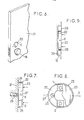
- buttons in question can even be provided "upside down” without any risk of error, as is the case when these buttons are provided on the rear face of a lock handle 18 in knob (FIG. 4) or on the underside of a lever handle 19 in a crowbar (FIG. 5).
- buttons are close enough, they can be actuated by two fingers of the same hand without it being necessary to move this hand during each complete unlocking maneuver: this circumstance further reduces the possibility identification of such a maneuver by his eyewitnesses.
- the two buttons are controlled from the same rocker permanently resiliently biased towards a central rest position.
- the bearing surface of this rocker can affect any desirable shape, for example that of a dihedral widely open towards the outside and of an edge parallel to the tilting axis: in such a case the supports exerted respectively on the two dihedral sections are used to activate the two buttons respectively.
- the rocker in question designated by the reference 22, is in the form of a cover having a flat bottom 23 and a peripheral edge 24 of relatively low constant height perpendicular to said bottom , the tilting axis X of this cover being parallel to the bottom 23 and passing through the edge 24.
- Special elastic means may be p re- seen to constantly remind the lid to its middle position.
- the cover 22 is mounted in such a way that its bottom 23 remains constantly in contact with each of the two buttons 1 and 2 or is arranged only at a very small distance from these buttons in its rest position: this is the first of these two hypotheses which was adopted in Figure 7.
- the outer face of the bottom 23, forming a support area for the user's fingers, is preferably flat, hard, smooth and relatively large, its surface generally being between 10 and 30 cm 2 .
- the cover may for this purpose be formed from an externally stamped metal plate smoothed by any desirable means such as brushing or an appropriate coating of chromium or other metal.
- the general shape of the bottom 23 may be that of a square, or of a rectangle (with the long side of this rectangle parallel or perpendicular to the axis X), or of an isosceles or equilateral triangle (with the axis of symmetry of this triangle parallel or perpendicular to the axis X), or of a trapezoid, etc.
- it is a circle whose radius is between 4 and 6 cm, the peripheral edge 24 then having a height between 5 and 7 mm.
- buttons 1 and 2 The actuation of the two buttons 1 and 2 is ensured by exerting an alternating series of presses in accordance with the code on the two halves of the bottom 23 respectively located on either side of the X axis.
- This X axis can be oriented horizontally or vertically.
- the different supports can all be executed successively using the same user finger, generally a thumb or index finger.
- the various supports can be easily executed using the index and middle fingers of the same hand of the user, oriented upwards.
- the control thus provided is particularly easy, even pleasant: in fact, because the support range is relatively large and smooth, the position of each support is not imposed with precision and we may consider that the control finger slides on said range, without loss of contact, from a position corresponding to the actuation of a button to a position corresponding to the actuation of the other button.
- the support surface is relatively large and flat, it can be used to receive any symbol or drawing.
- the cover 22 appears through a complementary light 28 hollowed out in a plate 29 suitable for closing itself a cavity 30 hollowed out in a masonry 31: the bottom 23 of this cover is then flush with the flat outer surface of said plate 29, in its rest state.
- the locking device according to the invention simultaneously eliminates all of the drawbacks indicated above for the known solutions of locking devices with key control.
- this code is composed of a relatively small number n of numbers or letters, this number being for example equal to 3, 4 or 5.
- the number of possible coded combinations is very high: this is how if the number of consecutive actuations of each button is between 1 and 16: the number of possible coded combinations is 65536 for an equal number n only 4.
Landscapes
- Physics & Mathematics (AREA)
- General Physics & Mathematics (AREA)
- Lock And Its Accessories (AREA)
- Credit Cards Or The Like (AREA)
- Supporting Of Heads In Record-Carrier Devices (AREA)
Priority Applications (1)
| Application Number | Priority Date | Filing Date | Title |
|---|---|---|---|
| AT82401010T ATE22589T1 (de) | 1981-06-04 | 1982-06-03 | Elektronisch kodierbare verriegelungsanordnungen. |
Applications Claiming Priority (2)
| Application Number | Priority Date | Filing Date | Title |
|---|---|---|---|
| FR8111102 | 1981-06-04 | ||
| FR8111102A FR2507411A1 (fr) | 1981-06-04 | 1981-06-04 | Perfectionnements aux dispositifs de verrouillage electronique a code |
Publications (2)
| Publication Number | Publication Date |
|---|---|
| EP0068936A1 true EP0068936A1 (de) | 1983-01-05 |
| EP0068936B1 EP0068936B1 (de) | 1986-10-01 |
Family
ID=9259196
Family Applications (1)
| Application Number | Title | Priority Date | Filing Date |
|---|---|---|---|
| EP82401010A Expired EP0068936B1 (de) | 1981-06-04 | 1982-06-03 | Elektronisch kodierbare Verriegelungsanordnungen |
Country Status (7)
| Country | Link |
|---|---|
| US (1) | US4485381A (de) |
| EP (1) | EP0068936B1 (de) |
| JP (1) | JPS57209373A (de) |
| AT (1) | ATE22589T1 (de) |
| CA (1) | CA1225841A (de) |
| DE (1) | DE3273536D1 (de) |
| FR (1) | FR2507411A1 (de) |
Cited By (3)
| Publication number | Priority date | Publication date | Assignee | Title |
|---|---|---|---|---|
| FR2593218A1 (fr) * | 1986-01-20 | 1987-07-24 | Pieddeloup Daniel | Dispositif d'asservissement par codification utilisant des generateurs d'impulsions d'origines techniques diverses |
| FR2669162A1 (fr) * | 1990-11-12 | 1992-05-15 | Houille Alain | Dispositif de formation d'un code numerique et appareil distributeur de produits equipe d'un tel dispositif. |
| WO1994017268A1 (de) * | 1993-01-28 | 1994-08-04 | Gerhard Weber | Schusselloses elektronisches schliesssystem |
Families Citing this family (13)
| Publication number | Priority date | Publication date | Assignee | Title |
|---|---|---|---|---|
| US4754423A (en) * | 1986-06-16 | 1988-06-28 | Motorola, Inc. | Electronic selector and method for selecting desired functions and levels |
| JPH0637187Y2 (ja) * | 1986-12-16 | 1994-09-28 | 自動車電機工業株式会社 | ドアロックアクチュエータ駆動装置 |
| US4912460A (en) * | 1987-07-16 | 1990-03-27 | John Chu | Electrostatically activated gating mechanism |
| US5563586A (en) * | 1994-07-29 | 1996-10-08 | Ambitech Industries, Inc. | Apparatus for limiting control of electrical equipment |
| FR2821107A1 (fr) * | 2001-02-22 | 2002-08-23 | Valeo Electronique | Systeme mains libres |
| US20050225431A1 (en) * | 2002-03-05 | 2005-10-13 | Jong-O Kim | Apparatus for opening/closing the door |
| US20120306614A1 (en) * | 2010-06-07 | 2012-12-06 | Essex Electronics, Inc. | Single element keyless control system |
| KR101618541B1 (ko) | 2013-03-15 | 2016-05-04 | 스펙트럼 브랜즈, 인크. | 통합형 안테나, 터치 작동부 및 광통신 장치를 갖는 무선 잠금장치 |
| US10300886B2 (en) * | 2016-03-15 | 2019-05-28 | GM Global Technology Operations LLC | Keyless control system |
| US11158145B2 (en) | 2016-03-22 | 2021-10-26 | Spectrum Brands, Inc. | Garage door opener with touch sensor authentication |
| US11450158B2 (en) | 2018-01-05 | 2022-09-20 | Spectrum Brands, Inc. | Touch isolated electronic lock |
| US11639617B1 (en) | 2019-04-03 | 2023-05-02 | The Chamberlain Group Llc | Access control system and method |
| CN116044256A (zh) * | 2022-10-18 | 2023-05-02 | 王栎焱 | 一种密码锁的加密方法及装置 |
Citations (7)
| Publication number | Priority date | Publication date | Assignee | Title |
|---|---|---|---|---|
| US3320395A (en) * | 1966-02-01 | 1967-05-16 | Allen Bradley Co | Operating mechanism for manually actuated switches |
| FR2070316A5 (de) * | 1969-12-01 | 1971-09-10 | Legrand Sa | |
| US3660729A (en) * | 1971-01-11 | 1972-05-02 | Bell Telephone Labor Inc | Electronic combination lock system |
| FR2107636A5 (de) * | 1970-09-14 | 1972-05-05 | Siemens Ag | |
| US3663781A (en) * | 1970-11-23 | 1972-05-16 | Scm Corp | Electrical switch having a flexible one-piece actuator |
| GB1314523A (en) * | 1969-01-31 | 1973-04-26 | Smiths Industries Ltd | Access-control equipment |
| US4222088A (en) * | 1978-09-27 | 1980-09-09 | Burton Richard H | Electronic lock |
Family Cites Families (7)
| Publication number | Priority date | Publication date | Assignee | Title |
|---|---|---|---|---|
| US1449248A (en) * | 1921-09-14 | 1923-03-20 | George D Rathbun | Combination locking mechanism |
| US3825898A (en) * | 1971-02-17 | 1974-07-23 | Phillips Screw Co | Safety lock with provision for key user identification |
| US3764982A (en) * | 1972-08-30 | 1973-10-09 | R Kidnocker | Sequentially coded actuating device |
| US4148092A (en) * | 1977-08-04 | 1979-04-03 | Ricky Martin | Electronic combination door lock with dead bolt sensing means |
| FR2420008A1 (fr) * | 1978-03-17 | 1979-10-12 | Neiman Sa | Dispositif de commande d'une serrure de vehicule automobile |
| JPS5548737A (en) * | 1978-10-02 | 1980-04-08 | Konishiroku Photo Ind Co Ltd | Photoelectrically focus detecting device mounted camera |
| FR2474574A1 (fr) * | 1980-01-25 | 1981-07-31 | Jacques Lewiner | Perfectionnements aux serrures de securite a combinaisons |
-
1981
- 1981-06-04 FR FR8111102A patent/FR2507411A1/fr active Granted
-
1982
- 1982-05-26 CA CA000403742A patent/CA1225841A/en not_active Expired
- 1982-06-03 AT AT82401010T patent/ATE22589T1/de not_active IP Right Cessation
- 1982-06-03 DE DE8282401010T patent/DE3273536D1/de not_active Expired
- 1982-06-03 EP EP82401010A patent/EP0068936B1/de not_active Expired
- 1982-06-04 JP JP57095020A patent/JPS57209373A/ja active Pending
- 1982-06-04 US US06/385,103 patent/US4485381A/en not_active Expired - Fee Related
Patent Citations (7)
| Publication number | Priority date | Publication date | Assignee | Title |
|---|---|---|---|---|
| US3320395A (en) * | 1966-02-01 | 1967-05-16 | Allen Bradley Co | Operating mechanism for manually actuated switches |
| GB1314523A (en) * | 1969-01-31 | 1973-04-26 | Smiths Industries Ltd | Access-control equipment |
| FR2070316A5 (de) * | 1969-12-01 | 1971-09-10 | Legrand Sa | |
| FR2107636A5 (de) * | 1970-09-14 | 1972-05-05 | Siemens Ag | |
| US3663781A (en) * | 1970-11-23 | 1972-05-16 | Scm Corp | Electrical switch having a flexible one-piece actuator |
| US3660729A (en) * | 1971-01-11 | 1972-05-02 | Bell Telephone Labor Inc | Electronic combination lock system |
| US4222088A (en) * | 1978-09-27 | 1980-09-09 | Burton Richard H | Electronic lock |
Cited By (3)
| Publication number | Priority date | Publication date | Assignee | Title |
|---|---|---|---|---|
| FR2593218A1 (fr) * | 1986-01-20 | 1987-07-24 | Pieddeloup Daniel | Dispositif d'asservissement par codification utilisant des generateurs d'impulsions d'origines techniques diverses |
| FR2669162A1 (fr) * | 1990-11-12 | 1992-05-15 | Houille Alain | Dispositif de formation d'un code numerique et appareil distributeur de produits equipe d'un tel dispositif. |
| WO1994017268A1 (de) * | 1993-01-28 | 1994-08-04 | Gerhard Weber | Schusselloses elektronisches schliesssystem |
Also Published As
| Publication number | Publication date |
|---|---|
| FR2507411A1 (fr) | 1982-12-10 |
| ATE22589T1 (de) | 1986-10-15 |
| JPS57209373A (en) | 1982-12-22 |
| CA1225841A (en) | 1987-08-25 |
| EP0068936B1 (de) | 1986-10-01 |
| DE3273536D1 (en) | 1986-11-06 |
| FR2507411B1 (de) | 1985-04-26 |
| US4485381A (en) | 1984-11-27 |
Similar Documents
| Publication | Publication Date | Title |
|---|---|---|
| EP0068936B1 (de) | Elektronisch kodierbare Verriegelungsanordnungen | |
| EP0099762B1 (de) | Kodierbare Fernsteuerungsanordnungen | |
| FR2796978A1 (fr) | Cylindre de serrure | |
| EP0196989B1 (de) | Elektromechanisches Schloss | |
| FR2699376A1 (fr) | Dispositif de verrouillage d'un mécanisme de fermeture pour bagage. | |
| EP2650457B1 (de) | Türöffnungssteuervorrichtung | |
| EP0147276B1 (de) | Kodierbare Steuerungsanordnungen | |
| EP0116001B1 (de) | Sicherheitseinrichtung für Türen, Fenster und dergleichen | |
| FR3042897B1 (fr) | Cadenas electronique connecte, procedes | |
| FR3081236A1 (fr) | Dispositif compact de commande de vitres electriques | |
| EP3584146B1 (de) | Fahrrad, das mit einem diebstahlschutzsystem mit blockierung der radgabel ausgestattet ist, und automatisches system zur bereitstellung eines solchen fahrrads | |
| JP3810691B2 (ja) | 携帯時計 | |
| WO2000035064A1 (fr) | Dispositif permettant de produire l'energie necessaire au fonctionnement d'un petit appareil electrique | |
| EP4007117B1 (de) | Energiesteuerungsverfahren für einen positionsdetektor eines beweglichen beschlagteils einer türzarge | |
| FR2561703A1 (fr) | Appareil d'acces a serrure et cle codee | |
| JP3296860B2 (ja) | 窓用クレセント | |
| EP2920655A2 (de) | Modus zur aktivierung einer elektronischen uhr | |
| FR3139932A1 (fr) | Système d’aide au maintien à domicile | |
| FR2539247A1 (fr) | Clavier a marquage de touches adaptable | |
| EP1662845B1 (de) | Verfahren zur Programmierung der Verzögerungsdauer eines Zeitschalters | |
| FR2693809A1 (fr) | Procédé de transmission de sécurité, par voie tactile, d'une information, à partir d'au moins un signe parmi N signes pré-sélectionnés et dispositifs pour sa mise en Óoeuvre. | |
| FR2493895A3 (fr) | Systeme electronique de deverrouillage d'un moyen d'actionnement | |
| FR2832017A1 (fr) | Telephone portable avec appel de fonctions par une action codee | |
| JPS6036173Y2 (ja) | 化粧用コンパクト | |
| FR2606819A1 (fr) | Procede et systeme electronique programmable pour commander l'ouverture de voies d'acces |
Legal Events
| Date | Code | Title | Description |
|---|---|---|---|
| PUAI | Public reference made under article 153(3) epc to a published international application that has entered the european phase |
Free format text: ORIGINAL CODE: 0009012 |
|
| AK | Designated contracting states |
Designated state(s): AT BE CH DE FR GB IT LI NL SE |
|
| 17P | Request for examination filed |
Effective date: 19830609 |
|
| GRAA | (expected) grant |
Free format text: ORIGINAL CODE: 0009210 |
|
| AK | Designated contracting states |
Kind code of ref document: B1 Designated state(s): AT BE CH DE FR GB IT LI NL SE |
|
| PG25 | Lapsed in a contracting state [announced via postgrant information from national office to epo] |
Ref country code: NL Effective date: 19861001 Ref country code: AT Effective date: 19861001 |
|
| REF | Corresponds to: |
Ref document number: 22589 Country of ref document: AT Date of ref document: 19861015 Kind code of ref document: T |
|
| ITF | It: translation for a ep patent filed | ||
| PG25 | Lapsed in a contracting state [announced via postgrant information from national office to epo] |
Ref country code: SE Effective date: 19861031 |
|
| REF | Corresponds to: |
Ref document number: 3273536 Country of ref document: DE Date of ref document: 19861106 |
|
| NLV1 | Nl: lapsed or annulled due to failure to fulfill the requirements of art. 29p and 29m of the patents act | ||
| PLBE | No opposition filed within time limit |
Free format text: ORIGINAL CODE: 0009261 |
|
| STAA | Information on the status of an ep patent application or granted ep patent |
Free format text: STATUS: NO OPPOSITION FILED WITHIN TIME LIMIT |
|
| 26N | No opposition filed | ||
| PGFP | Annual fee paid to national office [announced via postgrant information from national office to epo] |
Ref country code: GB Payment date: 19930528 Year of fee payment: 12 |
|
| PGFP | Annual fee paid to national office [announced via postgrant information from national office to epo] |
Ref country code: CH Payment date: 19930617 Year of fee payment: 12 |
|
| ITTA | It: last paid annual fee | ||
| PGFP | Annual fee paid to national office [announced via postgrant information from national office to epo] |
Ref country code: BE Payment date: 19930709 Year of fee payment: 12 |
|
| PG25 | Lapsed in a contracting state [announced via postgrant information from national office to epo] |
Ref country code: GB Effective date: 19940603 |
|
| PG25 | Lapsed in a contracting state [announced via postgrant information from national office to epo] |
Ref country code: LI Effective date: 19940630 Ref country code: CH Effective date: 19940630 Ref country code: BE Effective date: 19940630 |
|
| PGFP | Annual fee paid to national office [announced via postgrant information from national office to epo] |
Ref country code: DE Payment date: 19940630 Year of fee payment: 13 |
|
| BERE | Be: lapsed |
Owner name: BERTHIER GILBERT Effective date: 19940630 Owner name: HENNION CLAUDE Effective date: 19940630 Owner name: LEWINER JACQUES Effective date: 19940630 |
|
| GBPC | Gb: european patent ceased through non-payment of renewal fee |
Effective date: 19940603 |
|
| REG | Reference to a national code |
Ref country code: CH Ref legal event code: PL |
|
| PGFP | Annual fee paid to national office [announced via postgrant information from national office to epo] |
Ref country code: FR Payment date: 19950529 Year of fee payment: 14 |
|
| PG25 | Lapsed in a contracting state [announced via postgrant information from national office to epo] |
Ref country code: DE Effective date: 19960301 |
|
| PG25 | Lapsed in a contracting state [announced via postgrant information from national office to epo] |
Ref country code: FR Effective date: 19970228 |
|
| REG | Reference to a national code |
Ref country code: FR Ref legal event code: ST |