EP0069487A1 - Tropfberieselungsschlauch und Verfahren zu seiner Herstellung - Google Patents
Tropfberieselungsschlauch und Verfahren zu seiner Herstellung Download PDFInfo
- Publication number
- EP0069487A1 EP0069487A1 EP82303156A EP82303156A EP0069487A1 EP 0069487 A1 EP0069487 A1 EP 0069487A1 EP 82303156 A EP82303156 A EP 82303156A EP 82303156 A EP82303156 A EP 82303156A EP 0069487 A1 EP0069487 A1 EP 0069487A1
- Authority
- EP
- European Patent Office
- Prior art keywords
- tube
- sheet
- secondary tube
- sheet material
- passage
- Prior art date
- Legal status (The legal status is an assumption and is not a legal conclusion. Google has not performed a legal analysis and makes no representation as to the accuracy of the status listed.)
- Granted
Links
- 230000002262 irrigation Effects 0.000 title claims abstract description 43
- 238000003973 irrigation Methods 0.000 title claims abstract description 43
- 238000004519 manufacturing process Methods 0.000 title claims description 4
- 239000000463 material Substances 0.000 claims abstract description 53
- 230000002093 peripheral effect Effects 0.000 claims abstract description 18
- 230000000717 retained effect Effects 0.000 claims abstract description 6
- XLYOFNOQVPJJNP-UHFFFAOYSA-N water Substances O XLYOFNOQVPJJNP-UHFFFAOYSA-N 0.000 claims description 21
- 238000000034 method Methods 0.000 claims description 4
- 239000000853 adhesive Substances 0.000 description 6
- 230000001070 adhesive effect Effects 0.000 description 6
- 238000010276 construction Methods 0.000 description 6
- 229920003023 plastic Polymers 0.000 description 6
- 239000004033 plastic Substances 0.000 description 6
- 230000015572 biosynthetic process Effects 0.000 description 3
- 238000007789 sealing Methods 0.000 description 3
- 238000001125 extrusion Methods 0.000 description 2
- 239000010408 film Substances 0.000 description 2
- 230000014759 maintenance of location Effects 0.000 description 2
- 230000033228 biological regulation Effects 0.000 description 1
- 230000008021 deposition Effects 0.000 description 1
- 239000003621 irrigation water Substances 0.000 description 1
- 239000002650 laminated plastic Substances 0.000 description 1
- 238000012986 modification Methods 0.000 description 1
- 230000004048 modification Effects 0.000 description 1
- 238000003860 storage Methods 0.000 description 1
- 238000006467 substitution reaction Methods 0.000 description 1
- 239000010409 thin film Substances 0.000 description 1
Images



Classifications
-
- A—HUMAN NECESSITIES
- A01—AGRICULTURE; FORESTRY; ANIMAL HUSBANDRY; HUNTING; TRAPPING; FISHING
- A01G—HORTICULTURE; CULTIVATION OF VEGETABLES, FLOWERS, RICE, FRUIT, VINES, HOPS OR SEAWEED; FORESTRY; WATERING
- A01G25/00—Watering gardens, fields, sports grounds or the like
- A01G25/02—Watering arrangements located above the soil which make use of perforated pipe-lines or pipe-lines with dispensing fittings, e.g. for drip irrigation
-
- Y—GENERAL TAGGING OF NEW TECHNOLOGICAL DEVELOPMENTS; GENERAL TAGGING OF CROSS-SECTIONAL TECHNOLOGIES SPANNING OVER SEVERAL SECTIONS OF THE IPC; TECHNICAL SUBJECTS COVERED BY FORMER USPC CROSS-REFERENCE ART COLLECTIONS [XRACs] AND DIGESTS
- Y02—TECHNOLOGIES OR APPLICATIONS FOR MITIGATION OR ADAPTATION AGAINST CLIMATE CHANGE
- Y02A—TECHNOLOGIES FOR ADAPTATION TO CLIMATE CHANGE
- Y02A40/00—Adaptation technologies in agriculture, forestry, livestock or agroalimentary production
- Y02A40/10—Adaptation technologies in agriculture, forestry, livestock or agroalimentary production in agriculture
- Y02A40/22—Improving land use; Improving water use or availability; Controlling erosion
Definitions
- Drip irrigation conduits receive water under pressure and discharge the water at a slow trickle or drip rate. In order to do this, the irrigation conduit must substantially reduce the pressure of the water.
- pressure reduction is provided by using controlled orifices as shown, by way of example, in Chapin Reissue Patent No. 28,095 and Mock U.S. Patent No. 3,903,929 or by using an elongated capillary tube having a capillary passage of very small cross-sectional area as shown, by way of example, in allowed Menzel et al U.S. Patent No. 4,269,357.
- drip irrigation conduits typically include an elongated supply tube having a supply passage and one or more secondary tubes extending along the supply tube. Transfer ports extend between the supply passage and the passage of the secondary tube, and discharge ports extend from the passage of the secondary tube to the exterior of the irrigation conduit or to one or more. additional secondary tubes from which the water is ultimately discharged to the exterior of the irrigation conduit at the desired trickle rate.
- Drip irrigation conduits of this type can be extruded as shown by Mock U.S. Patent No. 3,903,929 or the secondary tube and a section of sheet material can be extruded as shown in the Menzel et al patent.
- the extrusion of the secondary tube in association with the supply tube or in association with sheet material to form the primary tube has been found somewhat difficult to control, particularly when the secondary tube is to be a capillary tube having a very small cross-sectional area capillary passage.
- extrusion of the supply tube precludes the use of inexpensive film materials and paper for the supply tube.
- Allport U.S. Patent No. 4,247,051 discloses a drip irrigation conduit in which a section of sheet material is joined together along longitudinally extending regions by circumferentially spaced and radially thick ribs of adhesive.
- the sheet material forms the supply passage, and the ribs and sheet material cooperate to define the secondary passage.
- the deposition of two or more relatively thick adhesive ribs of constant thickness and the careful pressurizing of the thick adhesive ribs between overlapping regions of the sheet material to form a secondary passage of controlled cross-sectional area is believed to be very difficult to accomplish in production.
- the secondary tube is initially provided as a separate tube completely detached from a supply tube or the sheet material from which the supply tube is to be made.
- the supply tube is constructed of a section of sheet material having longitudinally extending portions joined together to form a seam to thereby form the supply tube. Accordingly, the supply tube can be formed of a variety. of materials, including thin film plastics and paper.
- the supply tube and the secondary tube can be joined together in various different ways.
- a region of the sheet material extends at least part way around the periphery of the secondary tube, and the secondary tube is retained on such region of the sheet material.
- the secondary tube can be formed in any way that provides the desired control of the cross-sectional area of the secondary passage at a reasonable cost.
- a capillary tube it is preferred to extrude the secondary tube, and commercially available extruded tubing of suitable plastic material can be utilized.
- the secondary tube is preferably attached to the sheet material and then longitudinally extending portions of the sheet material are attached to each other to form the sheet material into the supply tube.
- Attaching of the secondary tube to the sheet material preferably includes bonding, as by an adhesive or heat sealing the secondary tube to the sheet material prior to forming the sheet material into the supply tube.
- the supply tube typically has a larger cross-sectional area when filled with water than the cross-sectional area of the passage of the secondary tube.
- the transfer ports, which lead from the supply passage to the secondary passage, and/or the discharge ports, which lead from the secondary passage to the exterior of the supply tube and the secondary tube, can advantageously be formed prior to the formation of the sheet material into the supply tube.
- the discharge ports extend from the secondary passage to the exterior of the irrigation conduit, although they may extend, if desired, into one or more additional secondary tubes for further pressure reduction of the water and ultimate-discharge of the water to the exterior of the irrigation conduit at the desired trickle rate.
- the retention of the secondary tube by the supply tube can be accomplished in many different ways in addition to, or in lieu of, the attachment between the secondary tube and sheet described above.
- the longitudinally extending portions can be overlapped to define a retaining tube, and the secondary tube may be retained within the retaining tube.
- the transfer ports preferably extend from the supply passage through one of the overlapping portions, and the peripheral wall of the secondary tube and the discharge ports extend through the peripheral wall of the secondary tube and the other of the overlapping portions.
- the sheet material may include first and second sheets of sheet material which define a retaining tube, and the secondary tube can be retained in the retaining tube between the sheets.
- the transfer ports preferably extend from the sup- ply passage through the second sheet and the peripheral wall of the secondary tube, and the discharge ports extend through the peripheral wall of the secondary tube and the first sheet.
- the sheet can be wrapped part way, for example, half way around the periphery of the secondary tube and suitably bonded to it.
- the transfer ports preferably extend through the peripheral wall of the secondary tube, and the discharge ports extend through the peripheral wall of the secondary tube and the sheet.
- the retention may include attaching the sheet material to the secondary tube along at least two zones of the sheet material, with such zones being spaced circumferentially on the secondary tube.
- the supply tube includes the region of the sheet material between such zones and the secondary tube also serves to close the supply tube.
- the transfer and discharge ports may extend solely through the secondary tube, and the sheet material may extend outwardly from the zones to define one or more flaps which can be used, for example, to prevent water which may be forced through the discharge ports at too high a velocity from being emitted as a stream.
- the flexible sheet is preferably formed so that it completely encloses the secondary tube.
- a second sheet is used to retain the secondary tube, such second sheet is preferably of lesser dimension than the first sheet and is also enclosed by the supply tube.
- the supply tube can be used to house and protect the other components of the irrigation conduit.
- This invention is also applicable to a drip irrigation conduit which comprises a plurality of secondary tubes with transfer ports leading from the supply passage to each of the secondary tubes, and with discharge ports leading from each of the secondary tubes to the exterior of the irrigation conduit or to additional secondary tubes which in turn lead to the exterior of the irrigation conduit.
- Figs. 3-5 show an irrigation conduit 11 constructed from a preformed, secondary tube 13 and a sheet 15 of flexible, water impervious sheet-material.
- the secondary tube 13 can be seamed or seamless, in the embodiment illustrated, it is a seamless extruded capillary tube of generally cylindrical configuration having a cylindrical peripheral wall 17 and a cylindrical axial secondary passage 19.
- the secondary tube 13 is preferably flexible and may be extruded from a suitable water impervious plastic material.
- controlled orifice pressure regulation could be utilized, in the embodiment illustrated, the secondary passage 19 is of very small diameter so that it affords a substantial restriction to flow which is sufficient to provide the desired drip or trickle irrigation. All of the illustrated embodiments of the invention may achieve trickle flow using a capillary or controlled orifice.
- the sheet 15 may be constructed of various materials, including paper, impregnated paper, plastic, a paper-plastic laminate, etc.
- the sheet 15 is constructed of a laminate which comprises a layer 21 (Fig. 6) of biodegradable paper sandwiched between an inner layer 23 and an outer layer 25 of extremely thin substantially impervious film plastic.
- the tube 13 and the sheet 15 are elongated, and the sheet has longitudinally extending portions in the form of longitudinally extending edge portions 27 and 29.
- the tube 13 is bonded to the edge portion 27 of the sheet 15 by heat sealing of the abutting plastic materials and/or by an adhesive along a zone 31, with the bond preferably extending continuously along the secondary tube.
- a plurality of transfer ports 33 are preferably formed through the sheet 15 and the peripheral wall 17, with the sheet 15 in the flat condition.
- the sheet 15 is folded to bring the longitudinal edge portion 29 over the secondary tube 13 and the longitudinal edge portion as shown in Figs. 3 and 4, and the longitudinal edge portion are bonded together along two circumferentially spaced longitudinally extending zones 35 to thereby form a supply tube 37 and a retaining tube 39, both of which extend longitudinally.
- the supply tube 37 has a supply passage 41 which is adapted to be coupled to a source of irrigation water under pressure.
- the cross-sectional area of the supply passage 41 is substantially greater than the cross-sectional area of the secondary passage 19.
- the supply passage 41 and the supply tube 37 are illustrated in a generally cylindrical configuration, which is the general configuration they assume when subjected to water under pressure. However, because the supply tube 37 is formed of flexible sheet material, it can assume a flat condition for storage.
- the retaining tube 39 is separated from the supply passage 41 by the longitudinal edge portion 27, and it contains the secondary tube 13 in a retaining 1 passage 43.
- the retaining tube 39 protects the secondary tube 13 and protects the bonds 31 to assure that the secondary tube will not become inadvertently detached from the irrigation conduit.
- the secondary tube 13 is retained, in part, by the longitudinal edge portions 27 and 29 which completely surround the secondary tube.
- discharge ports 45 are formed through the longitudinal edge portion 27 and the peripheral wall 17.
- the discharge ports 45 could be formed with the sheet 15 in the flat condition of Figs. 1 and 2, formation of the discharge ports 45 after formation of the supply tube 37 eliminates the need to accurately align the portions of the discharge ports 45 when the sheet 15 is folded to form the supply tube 37.
- One of the transfer ports 33 can serve a plurality of the discharge ports 45, and the transfer ports 33 and the discharge ports 45 need not have controlled dimensions because the secondary passage 19 affords an adequate restriction to water flow to cause water to be emitted to the exterior of the irrigation conduit 11 by the discharge ports 45 at the desired trickle.or drip rate.
- the discharge ports 45 will typically be spaced apart greater distances than that shown in Figs. 3 and 5.
- one or more additional secondary tubes could be provided in series with the secondary tube 13, if desired, in which event, the discharge ports 45 would communicate with the next adjacent secondary tube.
- the cross-sectional area of the secondary passage 19 could be materially enlarged, and the ports 33 and 45 could be ap- .
- Figs. 7-10 show a second embodiment of the invention, and portions of this embodiment corresponding to the embodiment of Figs. 1-6 are designated by corresponding reference numerals followed by the letter "a.” Except as shown and described herein, the embodiment of Figs. 7-10 is identical to the embodiment of Figs. 1-6.
- the secondary tube 13a is held on a sheet which includes the sheet 15a and a sheet 51 which, in the embodiment illustrated, is much narrower than the sheet 15a.
- the sheet 15a and the sheet 51 each extend around about 180 degrees of the secondary tube 13a, and the sheet 51 is bonded to the sheet 15a as by heat sealing or an adhesive continuously along longitudinally extending regions 53.
- the secondary tube 13a is held between the sheets 15a and 51 which form a retaining tube 39a.
- the tube 13a could be positioned at various locations transversely of the sheet 15a, in the form shown in Fig. 7,.it is centrally positioned with respect to the sheet 15a and extends longitudinally thereof.
- the sheet 51 may be constructed of a material which is identical to the material of the sheet 15a.
- the transfer ports 33a and the discharge ports 45a are formed with the sheet 15a in the flat, unfolded condition of Fig. 7. As shown in Fig. 10, the transfer ports 33a extend through the sheet 51 and the peripheral wall 17a to the secondary passage 19a, and the discharge ports 45a extend through the peripheral wall 17a and the sheet 15a.
- the sheet 15a is then formed into the supply tube 37a by bonding the longitudinal edge portions 27a and 29a together along one or more longitudinally extending zones 35a to thereby form a longitudinally extending seam.
- the sheet 51 could be on the exterior of the irrigation conduit lla, it is shown within the supply passage 41a in Figs. 8 and 9.
- Figs. 11-14 illustrate a third embodiment of the invention, and portions of this embodiment corresponding, to portions of the embodiment of Fig. 1 are designated by corresponding reference numerals followed by the letter "b.” Except as specifically shown or described herein, the embodiment of Figs. 11-14 is identical to the embodiment of Figs. 1-6.
- the construction shown in Fig. 11 is identical to the construction shown in Fig. 7, except that the sheet 51 has been eliminated, and the secondary tube 13b is suitably bonded to a semi-circular region 61 of the sheet 15b along the full length and width of the region 61.
- the region 61 extends about one half of the way around the periphery of the secondary tube 13b.
- the transfer ports 33b which are preferably formed with the sheet 15b in its flat condition, extend solely through the peripheral wall 17b
- the discharge ports 45b which are also preferably formed with the sheet 15b in its flat condition, extend through the peripheral wall 17b and the region 61 of the sheet 15b.
- the sheet 15b could be formed into a cylindrical supply tube in the same manner as the embodiments of Figs. 1-10, it is helically wrapped as shown in Fig. 10 so that the secondary tube 13b extends longitudinally of the supply tube 37b in helical fashion.
- the helical secondary tube 13b is considered to extend longitudinally of the supply tube 37b in that it extends along a path, at least one component of which extends longitudinally along the supply tube.
- the longitudinally extending edge portions 27b and 29b are bonded together to form a helically extending seam.
- the other illustrated embodiments of this invention could be similarly helically formed so that the secondary tube extends helically.
- the sheet 15b is folded so that the secondary tube 13b is completely surrounded by the sheet 15b and lies within the supply passage 41b.
- Figs. 15-17 show a fourth embodiment of the invention which is also identical to the embodiment of Figs. 1-6, except to the extent shown or described herein. Portions of the embodiment of Figs. 15-17 corresponding to portions of the embodiment of Figs. 1-6 are designated by corresponding reference numerals followed by the letter "c.”
- the secondary tube 15c can be attached, and oriented with respect to the sheet 15c, essentially in the same manner as shown in Fig. 1.
- the transfer ports 33c and the discharge ports 45c are formed solely in the peripheral wall 17c, and this is preferably carried out with the sheet 15c in the flat condition of Fig. 1.
- the longitudinal edge portion 29c is bonded to the secondary tube 13c along a zone 71 which is spaced circumferentially along the secondary tube 13c from the zone 31.
- the zones 31 and 71 may be spaced circumferentially so that they lie substantially at the 10 o'clock and 2 o'clock positions of the secondary tube l3c as viewed in Fig. 16. This forms the sheet 15c into the supply tube 37c and the secondary tube 13c closes the supply tube.
- the edge portions 27c and 29c project beyond the zones 31 and 71, respectively, and away from the supply passage 41c to form flaps 73.
- the discharge ports 45c are located intermediate the flaps 73.
- the flaps 73 extend toward each other so that they can break up any water stream that may be emitted from the discharge ports 45c.
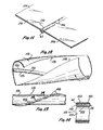
- Fig. 18 illustrates by way of example how the embodiment of Figs. 1-6 .can be modified to accommodate two secondary tubes 13d.
- the embodiment of Fig. 18 is identical to the embodiment of Figs. 1-6, and portions of the embodiment of Fig. 18 corresponding to portions of the embodiment of Figs. 1-6 are designated by corresponding reference numerals followed by the letter "d.”
- Fig. 18 the overlapping regions are widened and an intermediate zone 35d is provided along which the portions27d and 29d are bonded together to provide two parallel retaining tubes 39d for housing the two secondary tubes 13d, respectively.
- This provides two rows of discharge ports 45d, and the ports of each row can be axially offset, if desired.
Landscapes
- Life Sciences & Earth Sciences (AREA)
- Soil Sciences (AREA)
- Engineering & Computer Science (AREA)
- Water Supply & Treatment (AREA)
- Environmental Sciences (AREA)
- Infusion, Injection, And Reservoir Apparatuses (AREA)
Applications Claiming Priority (2)
| Application Number | Priority Date | Filing Date | Title |
|---|---|---|---|
| US275837 | 1981-06-22 | ||
| US06/275,837 US4474330A (en) | 1981-06-22 | 1981-06-22 | Drip irrigation conduit and method of making the same |
Publications (2)
| Publication Number | Publication Date |
|---|---|
| EP0069487A1 true EP0069487A1 (de) | 1983-01-12 |
| EP0069487B1 EP0069487B1 (de) | 1986-04-09 |
Family
ID=23054002
Family Applications (1)
| Application Number | Title | Priority Date | Filing Date |
|---|---|---|---|
| EP82303156A Expired EP0069487B1 (de) | 1981-06-22 | 1982-06-17 | Tropfberieselungsschlauch und Verfahren zu seiner Herstellung |
Country Status (5)
| Country | Link |
|---|---|
| US (1) | US4474330A (de) |
| EP (1) | EP0069487B1 (de) |
| AU (1) | AU546439B2 (de) |
| EG (1) | EG15344A (de) |
| PT (1) | PT75092B (de) |
Cited By (2)
| Publication number | Priority date | Publication date | Assignee | Title |
|---|---|---|---|---|
| EP0242327A3 (de) * | 1986-04-11 | 1988-02-03 | Nokia-Maillefer S.A. | Verfahren zur Herstellung eines Schlauches zur Tropfbewässerung und durch dieses Verfahren hergestellter Bewässerungsschlauch |
| US5732887A (en) * | 1988-02-16 | 1998-03-31 | Roberts; James C. | Drip irrigation tape and method of manufacture |
Families Citing this family (26)
| Publication number | Priority date | Publication date | Assignee | Title |
|---|---|---|---|---|
| US4548360A (en) * | 1982-02-08 | 1985-10-22 | William W. C. Delmer | Multichamber drip irrigation hose |
| US4923141A (en) * | 1984-01-11 | 1990-05-08 | Ryobi Ltd. | Spinning reel having reverse rotation preventing mechanism |
| US4807668A (en) * | 1985-03-01 | 1989-02-28 | Roberts James C | Drip irrigation tape |
| AT384146B (de) * | 1985-05-15 | 1987-10-12 | Arpe Plast Kunststoff | Rohr zur bewaesserung von pflanzen und verfahren zur herstellung eines rohres zur bewaesserung von pflanzen |
| US4880167A (en) * | 1987-09-23 | 1989-11-14 | James Hardie Irrigation, Inc. | Irrigation hose with linear turbulent flow emitter |
| US5318657A (en) * | 1988-02-16 | 1994-06-07 | Roberts James C | Drip irrigation tape and method of manufacture |
| IL95972A (en) * | 1990-10-12 | 1993-03-15 | Naan Irrigation Systems | Method and apparatus for producing pipes for drip irrigation |
| US5111995A (en) * | 1990-12-18 | 1992-05-12 | Rain Bird Sprinkler Mfg. Corp. | Drip irrigation tube |
| US5246171A (en) * | 1991-06-06 | 1993-09-21 | Roberts James C | Drip irrigation tape including a series of alternately offset elongated chambers |
| US5333793A (en) * | 1993-07-21 | 1994-08-02 | T-Systems International, Inc. | Drip irrigation hose with pressure compensation and method for its manufacture |
| US5591293A (en) * | 1994-11-14 | 1997-01-07 | Agrifim Irrigation Internaional N.V. | Process for manufacturing drip irrigation systems using plastic lamination/extrusion techniques |
| US6540158B1 (en) * | 2000-10-16 | 2003-04-01 | Netafim (A.C.S.) Ltd. | Double-line irrigation hose |
| AU783595B2 (en) * | 2000-10-18 | 2005-11-10 | Netafim Ltd | Double-line irrigation hose |
| USD450550S1 (en) | 2000-11-16 | 2001-11-20 | Roberts Group Holdings, Llc | Flow channel for drip irrigation with biased cavity |
| USD455055S1 (en) | 2000-11-16 | 2002-04-02 | Roberts Groups Holdings, Llc | Flow channel for drip irrigation with central cavity |
| US6874707B2 (en) * | 2001-05-31 | 2005-04-05 | Terra Spase | System for automated monitoring and maintenance of crops including computer control of irrigation and chemical delivery using multiple channel conduit |
| US20070166105A1 (en) * | 2006-01-04 | 2007-07-19 | William Rzadkowolski | Drainage system |
| US20080210785A1 (en) * | 2007-03-02 | 2008-09-04 | Fu-Jen Hou | Water feed pipe for use in irrigation |
| US8312671B2 (en) * | 2010-01-25 | 2012-11-20 | Developmental Technologies, Llc | Multi-chamber line and system for plant irrigation and fertigation and associated methods |
| US8714205B2 (en) * | 2010-10-06 | 2014-05-06 | Naandan Jain Irrigation C.S. Ltd. | Delayed degradability drip irrigation pipe |
| US8511596B2 (en) | 2010-10-14 | 2013-08-20 | Deere & Company | Drip tape management |
| AU2015270058B2 (en) | 2014-06-03 | 2019-05-23 | Jain Irrigation Systems Limited | A fluid conveying apparatus |
| US12559935B2 (en) * | 2023-04-18 | 2026-02-24 | Dupont Safety & Construction, Inc. | Foam envelope for sealing large volumes |
| US12492550B2 (en) * | 2023-04-18 | 2025-12-09 | Dupont Safety & Construction, Inc. | Foam envelope for sealing large volumes |
| US12454822B2 (en) * | 2023-04-18 | 2025-10-28 | Ddp Specialty Electronic Materials Us, Llc | Foam envelope for sealing large volumes |
| US12492551B2 (en) * | 2023-04-18 | 2025-12-09 | Dupont Safety & Construction, Inc. | Foam envelope for sealing large volumes |
Citations (2)
| Publication number | Priority date | Publication date | Assignee | Title |
|---|---|---|---|---|
| GB1484588A (en) * | 1974-11-15 | 1977-09-01 | Sahagun Barragan Jaime | Dripping irrigation tubing |
| FR2458993A1 (fr) * | 1979-06-19 | 1981-01-09 | Gilead Gideon | Appareil d'irrigation goutte a goutte pour l'agriculture et son procede de fabrication |
Family Cites Families (8)
| Publication number | Priority date | Publication date | Assignee | Title |
|---|---|---|---|---|
| US28095A (en) * | 1860-05-01 | Pike-escape | ||
| US3080124A (en) * | 1960-10-24 | 1963-03-05 | William G Rathmann | Soaker |
| USRE28095E (en) | 1973-03-15 | 1974-07-30 | Water distbibuting hose | |
| US4061272A (en) * | 1975-06-20 | 1977-12-06 | Winston Emanuel A | Irrigation device |
| JPS5714036Y2 (de) * | 1976-06-01 | 1982-03-23 | ||
| DE2643710C2 (de) * | 1976-09-28 | 1987-01-22 | Gilead, Gideon, Jerušalajim | Folienrohr sowie Vorrichtung zur Herstellung dieses Folienrohres |
| GB1582104A (en) * | 1977-02-08 | 1980-12-31 | Reed Irrigation Systems | Continuous drip irrigation tube |
| US4247051A (en) * | 1979-12-20 | 1981-01-27 | Davies Allport | Irrigation hose and method for its construction |
-
1981
- 1981-06-22 US US06/275,837 patent/US4474330A/en not_active Expired - Fee Related
-
1982
- 1982-06-17 EP EP82303156A patent/EP0069487B1/de not_active Expired
- 1982-06-18 AU AU84971/82A patent/AU546439B2/en not_active Ceased
- 1982-06-22 EG EG362/82A patent/EG15344A/xx active
- 1982-06-22 PT PT75092A patent/PT75092B/pt unknown
Patent Citations (2)
| Publication number | Priority date | Publication date | Assignee | Title |
|---|---|---|---|---|
| GB1484588A (en) * | 1974-11-15 | 1977-09-01 | Sahagun Barragan Jaime | Dripping irrigation tubing |
| FR2458993A1 (fr) * | 1979-06-19 | 1981-01-09 | Gilead Gideon | Appareil d'irrigation goutte a goutte pour l'agriculture et son procede de fabrication |
Cited By (4)
| Publication number | Priority date | Publication date | Assignee | Title |
|---|---|---|---|---|
| EP0242327A3 (de) * | 1986-04-11 | 1988-02-03 | Nokia-Maillefer S.A. | Verfahren zur Herstellung eines Schlauches zur Tropfbewässerung und durch dieses Verfahren hergestellter Bewässerungsschlauch |
| US4756339A (en) * | 1986-04-11 | 1988-07-12 | Maillefer Sa | Hose for drip irrigation and method of producing same |
| US4859264A (en) * | 1986-04-11 | 1989-08-22 | Maillefer Sa | Method and installation for producing hose for drip irrigation |
| US5732887A (en) * | 1988-02-16 | 1998-03-31 | Roberts; James C. | Drip irrigation tape and method of manufacture |
Also Published As
| Publication number | Publication date |
|---|---|
| EG15344A (en) | 1989-03-30 |
| PT75092A (en) | 1982-07-01 |
| AU546439B2 (en) | 1985-08-29 |
| AU8497182A (en) | 1983-01-06 |
| PT75092B (en) | 1983-12-19 |
| US4474330A (en) | 1984-10-02 |
| EP0069487B1 (de) | 1986-04-09 |
Similar Documents
| Publication | Publication Date | Title |
|---|---|---|
| EP0069487A1 (de) | Tropfberieselungsschlauch und Verfahren zu seiner Herstellung | |
| US4541569A (en) | Drip irrigation conduit and method of making the same | |
| US4880167A (en) | Irrigation hose with linear turbulent flow emitter | |
| US4807668A (en) | Drip irrigation tape | |
| US5141360A (en) | Irrigation tubing | |
| EP1720401B1 (de) | Bewässerungsrohr | |
| US4702787A (en) | Process for making drip irrigation lines | |
| US5252162A (en) | Multiple chamber drip irrigation hose made from a single strip | |
| CN1333707A (zh) | 具有根系制止素带的滴灌管道 | |
| US4790975A (en) | Method and device for extrusion of a double wall plastics pipe | |
| US20080282609A1 (en) | Irrigation sheets | |
| JPS604742B2 (ja) | 連続滴下散水管 | |
| US5224796A (en) | Flat sided irrigation tubing | |
| JPS61282690A (ja) | 潅漑用チユ−ブ及びチユ−ブ組み立て方法 | |
| US4425172A (en) | Manifolds for strutted film | |
| NZ201198A (en) | Trickle irrigation conduit:secondary tube attached to supply tube formed from sheet | |
| CN1328625A (zh) | 制作管子的方法以及管子 | |
| JPH0835587A (ja) | 樹脂管 | |
| JPS63128381U (de) | ||
| JPS62165090A (ja) | フランジ付合成樹脂管とその製造方法 | |
| JPS5918806A (ja) | かんがい用導管 | |
| CN116784207B (zh) | 一种螺纹滴渗管装置及其制造方法 | |
| JP4501512B2 (ja) | ガスバリア性を有する合成樹脂管 | |
| CN86103543A (zh) | 滴灌带 | |
| JP2925071B2 (ja) | 断熱ホース |
Legal Events
| Date | Code | Title | Description |
|---|---|---|---|
| PUAI | Public reference made under article 153(3) epc to a published international application that has entered the european phase |
Free format text: ORIGINAL CODE: 0009012 |
|
| AK | Designated contracting states |
Designated state(s): FR GB IT NL |
|
| 17P | Request for examination filed |
Effective date: 19830627 |
|
| GRAA | (expected) grant |
Free format text: ORIGINAL CODE: 0009210 |
|
| AK | Designated contracting states |
Kind code of ref document: B1 Designated state(s): FR GB IT NL |
|
| ITF | It: translation for a ep patent filed | ||
| ET | Fr: translation filed | ||
| PLBE | No opposition filed within time limit |
Free format text: ORIGINAL CODE: 0009261 |
|
| STAA | Information on the status of an ep patent application or granted ep patent |
Free format text: STATUS: NO OPPOSITION FILED WITHIN TIME LIMIT |
|
| 26N | No opposition filed | ||
| PGFP | Annual fee paid to national office [announced via postgrant information from national office to epo] |
Ref country code: NL Payment date: 19870630 Year of fee payment: 6 |
|
| PGFP | Annual fee paid to national office [announced via postgrant information from national office to epo] |
Ref country code: FR Payment date: 19890616 Year of fee payment: 8 |
|
| PG25 | Lapsed in a contracting state [announced via postgrant information from national office to epo] |
Ref country code: GB Effective date: 19890617 |
|
| ITTA | It: last paid annual fee | ||
| PG25 | Lapsed in a contracting state [announced via postgrant information from national office to epo] |
Ref country code: NL Effective date: 19900101 |
|
| GBPC | Gb: european patent ceased through non-payment of renewal fee | ||
| NLV4 | Nl: lapsed or anulled due to non-payment of the annual fee | ||
| PG25 | Lapsed in a contracting state [announced via postgrant information from national office to epo] |
Ref country code: FR Effective date: 19910228 |
|
| REG | Reference to a national code |
Ref country code: FR Ref legal event code: ST |