EP0070662A1 - Small torus hydraulic torque converter with lock-up clutch - Google Patents
Small torus hydraulic torque converter with lock-up clutch Download PDFInfo
- Publication number
- EP0070662A1 EP0070662A1 EP82303627A EP82303627A EP0070662A1 EP 0070662 A1 EP0070662 A1 EP 0070662A1 EP 82303627 A EP82303627 A EP 82303627A EP 82303627 A EP82303627 A EP 82303627A EP 0070662 A1 EP0070662 A1 EP 0070662A1
- Authority
- EP
- European Patent Office
- Prior art keywords
- torus
- axial length
- converter
- damper
- ratio
- Prior art date
- Legal status (The legal status is an assumption and is not a legal conclusion. Google has not performed a legal analysis and makes no representation as to the accuracy of the status listed.)
- Withdrawn
Links
Images
Classifications
-
- F—MECHANICAL ENGINEERING; LIGHTING; HEATING; WEAPONS; BLASTING
- F16—ENGINEERING ELEMENTS AND UNITS; GENERAL MEASURES FOR PRODUCING AND MAINTAINING EFFECTIVE FUNCTIONING OF MACHINES OR INSTALLATIONS; THERMAL INSULATION IN GENERAL
- F16H—GEARING
- F16H45/00—Combinations of fluid gearings for conveying rotary motion with couplings or clutches
- F16H45/02—Combinations of fluid gearings for conveying rotary motion with couplings or clutches with mechanical clutches for bridging a fluid gearing of the hydrokinetic type
-
- F—MECHANICAL ENGINEERING; LIGHTING; HEATING; WEAPONS; BLASTING
- F16—ENGINEERING ELEMENTS AND UNITS; GENERAL MEASURES FOR PRODUCING AND MAINTAINING EFFECTIVE FUNCTIONING OF MACHINES OR INSTALLATIONS; THERMAL INSULATION IN GENERAL
- F16H—GEARING
- F16H41/00—Rotary fluid gearing of the hydrokinetic type
- F16H41/24—Details
- F16H41/26—Shape of runner blades or channels with respect to function
-
- F—MECHANICAL ENGINEERING; LIGHTING; HEATING; WEAPONS; BLASTING
- F16—ENGINEERING ELEMENTS AND UNITS; GENERAL MEASURES FOR PRODUCING AND MAINTAINING EFFECTIVE FUNCTIONING OF MACHINES OR INSTALLATIONS; THERMAL INSULATION IN GENERAL
- F16H—GEARING
- F16H45/00—Combinations of fluid gearings for conveying rotary motion with couplings or clutches
- F16H45/02—Combinations of fluid gearings for conveying rotary motion with couplings or clutches with mechanical clutches for bridging a fluid gearing of the hydrokinetic type
- F16H2045/0273—Combinations of fluid gearings for conveying rotary motion with couplings or clutches with mechanical clutches for bridging a fluid gearing of the hydrokinetic type characterised by the type of the friction surface of the lock-up clutch
- F16H2045/0294—Single disk type lock-up clutch, i.e. using a single disc engaged between friction members
Definitions
- This invention is directed to a torque converter which will meet the needs noted above.
- a hydraulic torque converter with an input including an impeller, an output including a turbine and a reaction member including a stator.
- the impeller, turbine and stator define a small torus of conventional configuration but of reduced dimensional relationships relative to its outer radius. This places the torus farther from the converter axis than heretofore had been considered desirable. With such an arrangement, an improvement in the starting torque multiplication factor is obtained.
- this arrangement provides space inboard of the torus for placement of the damper of an associated lock-up clutch. As a result, the combined axial length of the torus and lock-up clutch is reduced over that shown in the prior art.
- a torque converter with a small torus of conventional configuration has been constructed in accordance with this invention such that R i equals approximately 0.56 R , L t equals approximately 0.50 R o and H equals aproximately 0.88 L t . Slight variations from these relationships may produce acceptable operation.
- R i provides increased space between axis A and torus 34. This affords room for placement of damper 40 substantially fully inboard of torus 34; that is, substantially fully between axis A and stator 28. This also allows placement of damper 40 in such a position that substantially one-half or more of its axial length L d overlaps the axial length L of torus 34. As a result, the combined axial length L c of torus 34 and damper 40 is reduced. Indeed, L c is less than L t plus approximately one-half L d . As a result, the overall axial length of converter 10 is shortened, which is consistent with the requirements of modern vehicles.
Landscapes
- Engineering & Computer Science (AREA)
- General Engineering & Computer Science (AREA)
- Mechanical Engineering (AREA)
- Catalysts (AREA)
- Control Of Fluid Gearings (AREA)
Abstract
A three-element hydraulic torque converter (10) includes a torus which is of conventional configuration but which is dimensionally small relative to its outer radius (R0). By increasing the inner radius (R1) of the torus, the starting torque multiplication factor is improved. In addition, the increased inner radius provides room inboard of the torus for placement of the torsional vibration damper (40) of an associated lock-up clutch (36).
Description
- This invention relates generally to a hydrodynamic power transmitting device useful with a mechanical coupling. More particularly, it relates to a hydraulic torque converter with a lock-up clutch, wherein the converter torus is dimensionally small but of conventional configuration, and wherein the associated lock-up clutch includes a torsional vibration damper oriented substantially inboard of the torus.
- In recent years, considerable effort has been expended to downsize and improve the efficiency of automotive vehicles. In instances where an automotive vehicle incorporates an automatic transmission, it is known that torque converter efficiency is improved with the use of a lock-up clutch. U.S. Patent 3,001,415 issued September 26, 1961 and U.S. Patent 3,185,273 issued May 25, 1965 disclose conventional torque converters in association with lock-up clutches. However, in each instance the combined axial length of the converter torus and lock-up clutch increases significantly the overall axial length of the torque converter. This is undesirable for use in a small vehicle.
- U. S. Patent 4,044,556 issued August 30, 1977 discloses a torque converter including a torus having a pear-shaped configuration in association with a lock-up clutch. Although this arrangement reduces somewhat the overall axial length of the torque converter, the particular torus configuration causes variation in the rate of fluid flow therein. This introduces losses into the system, and results in reduced converter operating efficiency.
- There remains a need in the art for a torque converter including a torus which will afford high operating efficiency. Further, when the torus is used in association with a lock-up clutch, they should be so arranged as to minimize the overall axial length of the torque converter.
- This invention is directed to a torque converter which will meet the needs noted above. To that end, there is provided a hydraulic torque converter with an input including an impeller, an output including a turbine and a reaction member including a stator. The impeller, turbine and stator define a small torus of conventional configuration but of reduced dimensional relationships relative to its outer radius. This places the torus farther from the converter axis than heretofore had been considered desirable. With such an arrangement, an improvement in the starting torque multiplication factor is obtained. In addition, this arrangement provides space inboard of the torus for placement of the damper of an associated lock-up clutch. As a result, the combined axial length of the torus and lock-up clutch is reduced over that shown in the prior art.
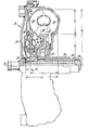
- The objects and advantages of this invention will become apparent to those skilled in the art upon careful consideration of the specification herein, including the drawing, which is a sectional view showing details of the torque converter, lock-up clutch and damper.
- While this invention is susceptible of embodiment in many different forms, a preferred embodiment is shown in the drawing and described in detail. It should be understood that the present disclosure is considered to be an exemplification of the principles of the invention, and is not intended to limit the invention to this embodiment.
- Referring to the drawing in greater detail, a three-element hydraulic
torque converter assembly 10 is supported for rotation on an axisA. Converter assembly 10 includes aninput member 12 adapted for driven engagement with an associated automotive engine.Input member 12 forms a converter housing which supports animpeller 14, and which includes a quill 16 adapted for driving engagement with the oil pump (not shown) of an associated transmission. - An
output member 18 supports aturbine 20.Output member 18 is secured to ahub 22 which in turn is secured to anoutput shaft 24. Shaft 24 may be the input shaft of an associated transmission. - A
reaction member 26 supports astator 28.Reaction member 26 is coupled through a one-way clutch 30 with aquill 32.Quill 32 may be grounded to the case of an associated transmission. -
Impeller 14,turbine 20 andstator 28 together define atorus 34 of conventional configuration so as to maintain, for all practical purposes, a constant rate of fluid flow therein.Torus 34 has an outer radius R and an inner radius Ri, both measured from the torus to axis A, a radial height H equal to R minus Ri, and an axial length Lt measured parallel to axis A. - The dimensional relationship of Ri to R0 is unique as compared with the prior art. Ri is equal to at least one-half Ro and preferably is greater than one-half Ro. In other words, in a preferred form of the invention Ri is equal to or greater than H. With Ri relatively large,
torus 34 is dimensionally smaller, as related to R , than what heretofore had been considered desirable. The dimensional relationship of H to Lt is conventional. - A torque converter with a small torus of conventional configuration has been constructed in accordance with this invention such that Ri equals approximately 0.56 R , Lt equals approximately 0.50 Ro and H equals aproximately 0.88 Lt. Slight variations from these relationships may produce acceptable operation.
- Tests of a torque converter with a small torus, having the just-described relationships, show the attainment of a starting torque multiplication factor of approximately 2.3. This compares favorably with a factor of 2.0 which heretofore has been considered satisfactory.
-
Torque converter assembly 10 also includes a lock-up clutch assembly 36. Assembly 36 includes a fluid-actuated clutch 38 adapted for engagement withinput member 12. Assembly 36 also includes a torsional vibration damper 40 which couples clutch 38 throughhub 22 withoutput shaft 24. Damper 40 has an axial length Ld. U.S. Patent 4,232,534 issued November 11, 1980 discloses a damper which may be suitable for use in assembly 36. - The extension of Ri provides increased space between axis A and
torus 34. This affords room for placement of damper 40 substantially fully inboard oftorus 34; that is, substantially fully between axis A andstator 28. This also allows placement of damper 40 in such a position that substantially one-half or more of its axial length Ld overlaps the axial length L oftorus 34. As a result, the combined axial length Lc oftorus 34 and damper 40 is reduced. Indeed, Lc is less than Lt plus approximately one-half Ld. As a result, the overall axial length ofconverter 10 is shortened, which is consistent with the requirements of modern vehicles. - It is not intended that the present invention be restricted in its application to an automotive environment. It is contemplated that the invention will be utilized in a wide variety of other applications.
Claims (10)
1. A hydraulic torque converter (10) having an axis (A), said converter comprising input means (12) including an impeller (14), output means (18) including a turbine (20), and reaction means (26) including a stator (28), said impeller, turbine and stator defining a torus (34) having an inner radius (R.) measured from said axis to the nearest point of the torus, an outer radius (R ) measured from said o axis to the farthest point of the torus, a radial height (H) measured between said points, and an axial length (Lt) measured parallel to said axis, the ratio of said inner radius (Ri) to said outer radius (R ) being at least 0.50 to 1.
2. The converter of claim 1, wherein the ratio of said inner radius (Ri) to said outer radius (R ) is greater than 0.50 to 1.
3. The converter of claim 1, wherein the ratio of said radial height (H) to said axial length (Lt) is not greater than 1 to 1.
4. The converter of claim 2, wherein the ratio of said radial height (H) to said axial length (Lt) is less than 1 to 1.
5. The converter of claim 2, wherein the ratio of said inner radius (Ri) to said outer radius (R ) is approximately 0.56 to 1, and the ratio of said radial height (H) to said outer radius (R ) is approximately 0.44 to 1.
6. The converter of claim 2, wherein the ratio of said axial length (Lt) to said outer radius (R ) is approximately 0.50 to 1, and the ratio of said radial height (H) to said axial length (Lt) is approximately 0.88 to 1.
7. The converter of claim 5, wherein the ratio of said axial length (Lt) to said outer radius (Ro) is approximately 0.50 to 1, and the ratio of said radial height (H) to said axial length (Lt) is approximately 0.88 to 1.
8. The converter of claim 1, 2, 3, 4, 5, 6 or 7, said converter (10) further comprising lock-up clutch means (36) including a damper (40) substantially fully inboard of said torus.
9. The converter of claim 1, 2, 3, 4, 5, 6 or 7, said converter (10) further comprising lock-up clutch means (36) including a damper (40) having an axial length (Ld), the combined axial length (Lc) said torus and damper being less than the axial length (Lt) of said torus plus approximately one-half the axial length (Ld) of said damper.
10. The converter of claim 1, 2, 3, 4, 5, 6 or 7, said converter (10) further comprising lock-up clutch means (36) including a damper (40) substantially fully inboard of said torus (34), said damper (40) having an axial length (Ld), the combined axial length (L ) said torus and damper being less than the axial length (Lt) of said torus plus approximately one-half the axial length (Ld) of said damper.
Applications Claiming Priority (2)
| Application Number | Priority Date | Filing Date | Title |
|---|---|---|---|
| US28522781A | 1981-07-20 | 1981-07-20 | |
| US285227 | 1981-07-20 |
Publications (1)
| Publication Number | Publication Date |
|---|---|
| EP0070662A1 true EP0070662A1 (en) | 1983-01-26 |
Family
ID=23093340
Family Applications (1)
| Application Number | Title | Priority Date | Filing Date |
|---|---|---|---|
| EP82303627A Withdrawn EP0070662A1 (en) | 1981-07-20 | 1982-07-09 | Small torus hydraulic torque converter with lock-up clutch |
Country Status (3)
| Country | Link |
|---|---|
| EP (1) | EP0070662A1 (en) |
| JP (1) | JPS5824650A (en) |
| AU (1) | AU8568882A (en) |
Cited By (14)
| Publication number | Priority date | Publication date | Assignee | Title |
|---|---|---|---|---|
| EP0253493A1 (en) * | 1986-07-16 | 1988-01-20 | Borg-Warner Automotive, Inc. | Drive hub for torque converter clutch |
| US4919241A (en) * | 1987-01-22 | 1990-04-24 | Kabushiki Kaisha Daikin Seisakusho | Lockup damper for torque converter |
| FR2706969A1 (en) * | 1993-06-23 | 1994-12-30 | Fichtel & Sachs Ag | |
| GB2255395B (en) * | 1991-05-02 | 1996-01-10 | Luk Lamellen & Kupplungsbau | Force transfer device |
| WO2001023779A1 (en) * | 1999-09-29 | 2001-04-05 | Valeo | Hydrokinetic coupling device comprising an improved overrunning clutch |
| FR2800143A1 (en) * | 1999-09-29 | 2001-04-27 | Valeo | Simplified hydrokinetic coupling for motor vehicle transmission includes clutch having outer ring, and lateral flange defining radial annular space for needle bearing |
| US6464054B2 (en) * | 2000-02-04 | 2002-10-15 | Exedy Corporation | Hydraulic torque transmitting device |
| US6595335B2 (en) | 2000-03-29 | 2003-07-22 | Mannesmannn Sachs Ag | Hydrodynamic coupling device |
| WO2004042255A1 (en) * | 2002-11-08 | 2004-05-21 | Voith Turbo Gmbh & Co. Kg | Hydrodynamic clutch and a start unit |
| US6957530B2 (en) | 2002-12-06 | 2005-10-25 | Zf Sachs Ag | Hydrodynamic torque converter |
| DE19680645B4 (en) * | 1995-06-22 | 2008-05-08 | Valeo | Housing for a hydrodynamic transmission and hydrodynamic transmission with such a housing |
| EP2175168A1 (en) | 2008-10-08 | 2010-04-14 | Zf Friedrichshafen Ag | Hydrodynamic torque converter |
| CN102072302A (en) * | 2010-12-16 | 2011-05-25 | 蚌埠市华泰液力变矩器有限公司 | Hydraulic torque converter |
| DE10154286B4 (en) * | 2000-11-15 | 2011-07-21 | Exedy Corp., Osaka | torque converter |
Families Citing this family (1)
| Publication number | Priority date | Publication date | Assignee | Title |
|---|---|---|---|---|
| JP7045477B2 (en) | 2018-10-17 | 2022-03-31 | ジヤトコ株式会社 | Torque converter |
Citations (5)
| Publication number | Priority date | Publication date | Assignee | Title |
|---|---|---|---|---|
| DE1265520B (en) * | 1964-03-25 | 1968-04-04 | Elmeg | Hydrodynamic torque converter |
| GB1131935A (en) * | 1964-11-10 | 1968-10-30 | Ferudo Sa Franc | Hydraulic torque converter |
| US3503209A (en) * | 1967-09-02 | 1970-03-31 | Fichtel & Sachs Ag | Hydraulic torque converter |
| US4044556A (en) * | 1975-12-26 | 1977-08-30 | Toyota Jidosha Kogyo Kabushiki Kaisha | Hydraulic torque converter with a lock-up clutch |
| GB2017835A (en) * | 1978-04-04 | 1979-10-10 | Nissan Motor | Lock-up torque converter with compact arrangement of damper |
-
1982
- 1982-07-07 AU AU85688/82A patent/AU8568882A/en not_active Abandoned
- 1982-07-09 EP EP82303627A patent/EP0070662A1/en not_active Withdrawn
- 1982-07-16 JP JP12429882A patent/JPS5824650A/en active Pending
Patent Citations (5)
| Publication number | Priority date | Publication date | Assignee | Title |
|---|---|---|---|---|
| DE1265520B (en) * | 1964-03-25 | 1968-04-04 | Elmeg | Hydrodynamic torque converter |
| GB1131935A (en) * | 1964-11-10 | 1968-10-30 | Ferudo Sa Franc | Hydraulic torque converter |
| US3503209A (en) * | 1967-09-02 | 1970-03-31 | Fichtel & Sachs Ag | Hydraulic torque converter |
| US4044556A (en) * | 1975-12-26 | 1977-08-30 | Toyota Jidosha Kogyo Kabushiki Kaisha | Hydraulic torque converter with a lock-up clutch |
| GB2017835A (en) * | 1978-04-04 | 1979-10-10 | Nissan Motor | Lock-up torque converter with compact arrangement of damper |
Cited By (23)
| Publication number | Priority date | Publication date | Assignee | Title |
|---|---|---|---|---|
| EP0253493A1 (en) * | 1986-07-16 | 1988-01-20 | Borg-Warner Automotive, Inc. | Drive hub for torque converter clutch |
| US4919241A (en) * | 1987-01-22 | 1990-04-24 | Kabushiki Kaisha Daikin Seisakusho | Lockup damper for torque converter |
| GB2255395B (en) * | 1991-05-02 | 1996-01-10 | Luk Lamellen & Kupplungsbau | Force transfer device |
| FR2706969A1 (en) * | 1993-06-23 | 1994-12-30 | Fichtel & Sachs Ag | |
| GB2279433A (en) * | 1993-06-23 | 1995-01-04 | Fichtel & Sachs Ag | Hydrodynamic torque converter |
| US5515956A (en) * | 1993-06-23 | 1996-05-14 | Fichtel & Sachs Ag | Hydrokinetic torque converter |
| GB2279433B (en) * | 1993-06-23 | 1996-07-24 | Fichtel & Sachs Ag | Hydrodynamic torque converter |
| DE4320769C2 (en) * | 1993-06-23 | 2001-09-13 | Mannesmann Sachs Ag | Hydrodynamic torque converter with lock-up clutch |
| DE19680645B4 (en) * | 1995-06-22 | 2008-05-08 | Valeo | Housing for a hydrodynamic transmission and hydrodynamic transmission with such a housing |
| WO2001023779A1 (en) * | 1999-09-29 | 2001-04-05 | Valeo | Hydrokinetic coupling device comprising an improved overrunning clutch |
| FR2800143A1 (en) * | 1999-09-29 | 2001-04-27 | Valeo | Simplified hydrokinetic coupling for motor vehicle transmission includes clutch having outer ring, and lateral flange defining radial annular space for needle bearing |
| US6464054B2 (en) * | 2000-02-04 | 2002-10-15 | Exedy Corporation | Hydraulic torque transmitting device |
| DE10015701B4 (en) * | 2000-03-29 | 2007-10-25 | Zf Sachs Ag | Hydrodynamic coupling device |
| US6595335B2 (en) | 2000-03-29 | 2003-07-22 | Mannesmannn Sachs Ag | Hydrodynamic coupling device |
| DE10154286B4 (en) * | 2000-11-15 | 2011-07-21 | Exedy Corp., Osaka | torque converter |
| WO2004042255A1 (en) * | 2002-11-08 | 2004-05-21 | Voith Turbo Gmbh & Co. Kg | Hydrodynamic clutch and a start unit |
| US6957530B2 (en) | 2002-12-06 | 2005-10-25 | Zf Sachs Ag | Hydrodynamic torque converter |
| US7152400B2 (en) | 2002-12-06 | 2006-12-26 | Zf Sachs Ag | Hydrodynamic torque converter |
| DE10257349B4 (en) * | 2002-12-06 | 2011-08-11 | ZF Sachs AG, 97424 | Hydrodynamic torque converter |
| EP2175168A1 (en) | 2008-10-08 | 2010-04-14 | Zf Friedrichshafen Ag | Hydrodynamic torque converter |
| DE102008042665A1 (en) | 2008-10-08 | 2010-04-29 | Zf Friedrichshafen Ag | Hydrodynamic torque converter |
| US8418450B2 (en) | 2008-10-08 | 2013-04-16 | Zf Friedrichshafen Ag | Hydrodynamic clutch arrangement |
| CN102072302A (en) * | 2010-12-16 | 2011-05-25 | 蚌埠市华泰液力变矩器有限公司 | Hydraulic torque converter |
Also Published As
| Publication number | Publication date |
|---|---|
| JPS5824650A (en) | 1983-02-14 |
| AU8568882A (en) | 1983-01-27 |
Similar Documents
| Publication | Publication Date | Title |
|---|---|---|
| EP0070662A1 (en) | Small torus hydraulic torque converter with lock-up clutch | |
| US5771691A (en) | Torque converter having spatially oriented flat turbine blades | |
| US4646886A (en) | Damper device of a clutch for a torque converter | |
| US4044556A (en) | Hydraulic torque converter with a lock-up clutch | |
| US5462145A (en) | Hydrokinetic lockup torque converter with lockup clutch | |
| JP2009041662A (en) | Torque converter with lock-up clutch | |
| CA1101308A (en) | Hydrokinetic torque converter with lock-up clutch | |
| GB2107806A (en) | Multiple ratio power transmission mechanism | |
| GB1464363A (en) | Hydrodynamic-mechanical transmissions | |
| US4405038A (en) | Device for troque transmission between a drive shaft, e.g. an engine crankshaft, and an attachment unit such as a hydrodynamic retarder | |
| US4159654A (en) | Automatic transmission apparatus | |
| GB2279432A (en) | Hydrodynamic torque converter | |
| EP0253493B1 (en) | Drive hub for torque converter clutch | |
| US5655368A (en) | Viscous damper for hydraulic power transmission | |
| US6041905A (en) | Coil spring assembly for a lock-up damper | |
| US5746296A (en) | Torque converter having lock-up clutch | |
| US20080245635A1 (en) | Lock-up torque converter and method of locking up a torque converter | |
| US5660258A (en) | Torque converter having torsional damper | |
| US6931844B2 (en) | Fluid coupling | |
| US8418450B2 (en) | Hydrodynamic clutch arrangement | |
| US6779639B2 (en) | Fluid transmission system with lock-up clutch | |
| US3362259A (en) | Vehicle power plant | |
| US6827187B2 (en) | Hydrodynamic coupling device | |
| US6866130B2 (en) | Torque converter | |
| US5259191A (en) | Torque converter |
Legal Events
| Date | Code | Title | Description |
|---|---|---|---|
| PUAI | Public reference made under article 153(3) epc to a published international application that has entered the european phase |
Free format text: ORIGINAL CODE: 0009012 |
|
| AK | Designated contracting states |
Designated state(s): DE FR GB IT |
|
| 17P | Request for examination filed |
Effective date: 19830307 |
|
| STAA | Information on the status of an ep patent application or granted ep patent |
Free format text: STATUS: THE APPLICATION IS DEEMED TO BE WITHDRAWN |
|
| 18D | Application deemed to be withdrawn |
Effective date: 19840516 |
|
| RIN1 | Information on inventor provided before grant (corrected) |
Inventor name: SCHULZ, WILLIS L. |