EP0078678A1 - Procédé et dispositif pour nettoyer des filtres - Google Patents
Procédé et dispositif pour nettoyer des filtres Download PDFInfo
- Publication number
- EP0078678A1 EP0078678A1 EP82305764A EP82305764A EP0078678A1 EP 0078678 A1 EP0078678 A1 EP 0078678A1 EP 82305764 A EP82305764 A EP 82305764A EP 82305764 A EP82305764 A EP 82305764A EP 0078678 A1 EP0078678 A1 EP 0078678A1
- Authority
- EP
- European Patent Office
- Prior art keywords
- filter cloth
- filter
- gas
- air
- passage
- Prior art date
- Legal status (The legal status is an assumption and is not a legal conclusion. Google has not performed a legal analysis and makes no representation as to the accuracy of the status listed.)
- Granted
Links
- 238000004140 cleaning Methods 0.000 title claims abstract description 53
- 238000000034 method Methods 0.000 title claims description 32
- 239000004744 fabric Substances 0.000 claims abstract description 196
- 238000011001 backwashing Methods 0.000 claims abstract description 54
- 239000012065 filter cake Substances 0.000 claims abstract description 48
- 230000000694 effects Effects 0.000 claims abstract description 14
- 238000001914 filtration Methods 0.000 claims description 70
- 239000007789 gas Substances 0.000 claims description 49
- 239000010419 fine particle Substances 0.000 claims description 12
- 238000011144 upstream manufacturing Methods 0.000 claims description 7
- 239000002245 particle Substances 0.000 description 42
- 239000013618 particulate matter Substances 0.000 description 13
- 239000000428 dust Substances 0.000 description 10
- 239000011148 porous material Substances 0.000 description 8
- 239000000843 powder Substances 0.000 description 7
- 230000002093 peripheral effect Effects 0.000 description 5
- 230000008569 process Effects 0.000 description 5
- 230000001464 adherent effect Effects 0.000 description 4
- 238000007796 conventional method Methods 0.000 description 3
- 230000009471 action Effects 0.000 description 2
- 230000003321 amplification Effects 0.000 description 2
- 238000010276 construction Methods 0.000 description 2
- 230000003467 diminishing effect Effects 0.000 description 2
- 238000007599 discharging Methods 0.000 description 2
- 230000005484 gravity Effects 0.000 description 2
- 230000006872 improvement Effects 0.000 description 2
- 239000007788 liquid Substances 0.000 description 2
- 230000007246 mechanism Effects 0.000 description 2
- 238000003199 nucleic acid amplification method Methods 0.000 description 2
- 230000000149 penetrating effect Effects 0.000 description 2
- 230000009467 reduction Effects 0.000 description 2
- 238000010521 absorption reaction Methods 0.000 description 1
- 230000003190 augmentative effect Effects 0.000 description 1
- 230000015572 biosynthetic process Effects 0.000 description 1
- 239000006229 carbon black Substances 0.000 description 1
- 238000004891 communication Methods 0.000 description 1
- 239000012141 concentrate Substances 0.000 description 1
- 238000004132 cross linking Methods 0.000 description 1
- 238000005520 cutting process Methods 0.000 description 1
- 238000013461 design Methods 0.000 description 1
- 230000006866 deterioration Effects 0.000 description 1
- 238000011161 development Methods 0.000 description 1
- 239000012530 fluid Substances 0.000 description 1
- 238000005243 fluidization Methods 0.000 description 1
- 230000001788 irregular Effects 0.000 description 1
- 238000012856 packing Methods 0.000 description 1
- 239000000049 pigment Substances 0.000 description 1
- 239000012716 precipitator Substances 0.000 description 1
- 238000011084 recovery Methods 0.000 description 1
- 238000004904 shortening Methods 0.000 description 1
- 239000013589 supplement Substances 0.000 description 1
- 230000002459 sustained effect Effects 0.000 description 1
Images


Classifications
-
- B—PERFORMING OPERATIONS; TRANSPORTING
- B01—PHYSICAL OR CHEMICAL PROCESSES OR APPARATUS IN GENERAL
- B01D—SEPARATION
- B01D46/00—Filters or filtering processes specially modified for separating dispersed particles from gases or vapours
- B01D46/24—Particle separators, e.g. dust precipitators, using rigid hollow filter bodies
- B01D46/2403—Particle separators, e.g. dust precipitators, using rigid hollow filter bodies characterised by the physical shape or structure of the filtering element
- B01D46/2411—Filter cartridges
-
- B—PERFORMING OPERATIONS; TRANSPORTING
- B01—PHYSICAL OR CHEMICAL PROCESSES OR APPARATUS IN GENERAL
- B01D—SEPARATION
- B01D46/00—Filters or filtering processes specially modified for separating dispersed particles from gases or vapours
- B01D46/0039—Filters or filtering processes specially modified for separating dispersed particles from gases or vapours with flow guiding by feed or discharge devices
- B01D46/0041—Filters or filtering processes specially modified for separating dispersed particles from gases or vapours with flow guiding by feed or discharge devices for feeding
- B01D46/0043—Filters or filtering processes specially modified for separating dispersed particles from gases or vapours with flow guiding by feed or discharge devices for feeding containing fixed gas displacement elements or cores
-
- B—PERFORMING OPERATIONS; TRANSPORTING
- B01—PHYSICAL OR CHEMICAL PROCESSES OR APPARATUS IN GENERAL
- B01D—SEPARATION
- B01D46/00—Filters or filtering processes specially modified for separating dispersed particles from gases or vapours
- B01D46/52—Particle separators, e.g. dust precipitators, using filters embodying folded corrugated or wound sheet material
- B01D46/521—Particle separators, e.g. dust precipitators, using filters embodying folded corrugated or wound sheet material using folded, pleated material
-
- B—PERFORMING OPERATIONS; TRANSPORTING
- B01—PHYSICAL OR CHEMICAL PROCESSES OR APPARATUS IN GENERAL
- B01D—SEPARATION
- B01D46/00—Filters or filtering processes specially modified for separating dispersed particles from gases or vapours
- B01D46/66—Regeneration of the filtering material or filter elements inside the filter
- B01D46/69—Regeneration of the filtering material or filter elements inside the filter by means acting on the cake side without movement with respect to the filter elements, e.g. fixed nozzles
-
- B—PERFORMING OPERATIONS; TRANSPORTING
- B01—PHYSICAL OR CHEMICAL PROCESSES OR APPARATUS IN GENERAL
- B01D—SEPARATION
- B01D46/00—Filters or filtering processes specially modified for separating dispersed particles from gases or vapours
- B01D46/66—Regeneration of the filtering material or filter elements inside the filter
- B01D46/70—Regeneration of the filtering material or filter elements inside the filter by acting counter-currently on the filtering surface, e.g. by flushing on the non-cake side of the filter
- B01D46/71—Regeneration of the filtering material or filter elements inside the filter by acting counter-currently on the filtering surface, e.g. by flushing on the non-cake side of the filter with pressurised gas, e.g. pulsed air
Definitions
- This invention relates to the filtering of gases containing fine particles and more particularly to a method and apparatus for cleaning the filter in such filtration apparatus.
- the filter cloth used in the aforementioned filters may be broadly classified into two types.
- the first is a thick unwoven fabric having an extremely coarse texture and a thickness of from 15 to 30mm
- the second also is an unwoven fabric having a fine surface and a thickness of from 1 to 2mm.
- particulate matter such as dust contained in the gas (which we will assume is air for the purpose of description) is caused to lodge within the filter texture thereby to be absorbed within the walls of the filter.
- the purpose of this filter is to incompletely collect the dust contained in the air stream only at a low concentration. Thus the particulate matter is removed imperfectly and cannot be reutilized.
- the second filter cloth does not ordinarily have a pore diameter as small as the particle diameter of the particles that are desired to be collected.
- the mean pore diameter in many cases ranges from 5 to 20 microns.
- Filtration of this kind belongs to the category of so-called cake filtration. Specifically, using a filter cloth of a pore diameter greater than the particle diameter of the particulate matter, a very minute proportion of the particulate matter passes completely through to the secondary side (inner side) of the filter cloth at the instant filtration begins, but immediately thereafter the particulate matter forms a layer, known as a filter cake, on the primary or outer surface of the filter cloth. The filter cake itself then begins acting as a filter to thenceforth enable complete collection of the particles.
- the flow velocity through the second filter cloth that is adopted for particle collection is ordinarily from 1 to 2 m/min (1.67 to 3.33 cm/sec). This is much lower than the flow velocity of 1 to 2 m/sec that can be realized with the first filter cloth. Accordingly, for a constant air flow rate, it is required that the second filter cloth have a very large area to assure proper operation.
- a flow velocity of up to 6 m/min (10 cm/sec). can be achieved.
- the particles extracted from the air form a filter cake by attaching to and accumulating on the upstream side (namely the primary side mentioned above, the opposite or downstream side being the secondary side) of the filter cloth with the passage of time.
- the formation of the filter cake causes the pressure - differential, measured across the primary to the secondary sides, to rise. Since an excessive rise in the pressure differential would be undesirable in terms of the inherent limitations upon the facilities that provide the air supply pressure and in terms of a deterioration in filter performance, it is required that the filter cake be removed from the filter cloth. It is also required that the particulate matter be recovered. For these reasons, it is general practice to provide a so-called dust removal mechanism for knocking the filter cake off the filter cloth automatically at such time that the filter cake attains a certain thickness.
- Two conventional techniques are available for effecting such dust removal.
- One is a so-called shaking method wherein the filter cloth is vibrated mechanically to shake off the filter cake.
- the other is a so-called backwashing method wherein pressurized air is momentarily blown down toward the second side of the filter, that is, from the inner side thereof, to dislodge the accumulated particles from the primary side of_the filter by means of the reverse air flow.
- This latter method is gaining wider popularity owing to its simpler construction.
- an outlet pipe through which clean air exits from the filtration apparatus employs flow velocities of from 1 to 3 m/sec for liquids and from 20 to 30 m/sec for gases, which are appropriate for ordinary fluid transport in terms of economy and space limitations.
- the outlet pipe flow velocity say 20 m/sec
- the filtration flow velocity say 3 cm/sec
- An object of the present invention is to provide a gas filter for gases containing fine particles or powder, through which all varieties of fine particles and powders can be collected completely and a filter cake clinging to a filter cloth can be dislodge from the cloth automatically.
- a method of cleaning a filter for filtering gases containing fine particles by passing the gases through a filter cloth from a primary side thereof to a secondary side is characterized in that a jet of gas is directed across the surface of the filter cloth through a passage substantially parallel thereto on the primary side thereof, the filter cloth forming at least one wall of the passage, whereby any filter cake on the surface of the primary side of the filter cloth is cleaned off by the flow of gas across its surface.
- the flow rate of air introduced externally during cleaning is held equal to or about twice that of the normal filtration flow rate of a single filter cloth, and the entire filter cake on the filter cloth is placed within the region of a high-speed stream at the instant of cleaning, whereby the filter cake may be freed and lifted away from the filter cloth in its entirety.
- the invention includes filter apparatus for filtering gases, containing fine particles, through a filter cloth, the apparatus including a device for cleaning off filter cake attached to the primary side of the filter cloth, characterized in that the device comprises means for emitting a jet of high-speed gas into a passage subtantially parallel to and on the primary side of the filter cloth to flow across the primary surface of the filter cloth, the filter cloth forming at least one wall of the passage.
- pressurized air may be jetted from a backwashing air orifice disposed in an outlet pipe to enhance the cleaning effect.
- FIG. 1 which illustrates a filtration apparatus and collecting vessel for backwashing according to the prior art
- the collecting vessel designated at numeral 3
- the collecting vessel has a ceiling plate 4 from which the filter cloths.1, 2 depend vertically, an outlet 5 for the collected fine particles or powder, and a pipe 6 for supplying the contaminated air which is to be filtered.
- Outlet pipes 7, 8 for the filtered clean air extend from the ceiling plate 4.
- the outlet pipes 7, 8 are penetrated by respective orifices 9, 10 each of which communicates with a source of pressurized air, not shown.
- Automatic valves 11, 12 are provided in the flow passages of the respective orifices 9, 10 for opening and closing these passages to the source of pressurized air.
- the arrow indicated at 13 shows the direction of contaminated air flow as it enters the apparatus, while the arrows at 14, 15 show the direction of the cleaned air flow exiting from the apparatus.
- Numeral 16 denotes the fine particles or powder collected at the bottom of the vessel 3, where a discharge value 17 is provided for discharging the collected particles.
- the air contaminated with the particulate matter is fed in continuously from the supply pipe 6.
- the major portion of the particulate matter is separated from the air flow by the influence of gravity and settles at the bottom of the vessel 3 for collection.
- the separating effect of gravity may be enhanced greatly by disposing the supply pipe 6 along a line which is tangent to the cylindrical wall of the collecting vessel 3. Since the valve 17 is closed, the air accompanied by the remaining free particles passes through the cylindrical filter cloths 1, 2 from the outer (primary) to the inner (secondary) sides thereof and then is discharged from the outlet pipes 7, 8 as clean air completely removed of particulate matter. During the course of this filtration cycle, the particles attach themselves to the outer surfaces of the filter cloths 1, 2 to be collected thereby.
- one of the filter cloths is subjected to a backwashing operation.
- This entails expelling a momentary jet of pressurized air for backwashing from the orifice 9.
- the purpose of this step is to blow off the particulate matter from the filter cloth 1 by the reverse flow of backwashing air travelling from the secondary side to the primary side of the filter cloth.
- jetted air which passes completely through the filter cloth 1 and exits from the primary (outer) side thereof is excess air that proceeds to flow through the filter cloth 2 in the normal direction (i.e., secondary to primary side) and then out through the outlet pipe 8.
- the cylindrical shape is often adopted because of structural simplicity.
- the surface area obtained would be 7,500 cm for a cylinder having a diameter (D) of 20 cm and a length (L) of 119 cm.
- L/D 6 .
- increasing the diameter (D) of the filter cloth would make it impossible to accommodate a large number of them in the vessel. It is inevitable, therefore, that the filter cloth configuration will be long and slender since the conventional method demands that L/D be large.
- the pressurized air is expelled from the orifice 9 for a very short period of time of, say, 0.2 sec. -
- an arrangement is required wherein the automatic valve 11 located upstream of the orifice 9 is rapidly opened for the time required, and then closed.
- Introducing the pressurized air for a long period of time is undesirable since it would send a large quantity of air into the collecting vessel 3 on the primary side of the filter cloth, adding to the air entering from the supply pipe 6 for the purpose of being treated.
- the short burst of backwashing air with as low a flow rate as possible, is preferred in order to reduce pressurized air consumption.
- the initial flow velocity of the pressurized air itself when jetted from the orifice 9 can attain a high speed approaching that of sound if the air pressure upstream of the orifice is two atmospheres (absolute) or more. Owing to this kinetic energy, an ejector effect is produced within the outlet pipe 7, whereby the excess air is made to join the expelled air to form an increased flow of air which exits from the primary side of the cloth filter via the secondary side thereof.
- tie total air flow rate in the reverse direction for the purpose of backwashing is limited to approximately the filtration flow rate (25,000 cm 3 /sec in this example) or, at best, to a value which is two to three times this figure. The reasons are as follows:
- the apparatus includes a filter cloth 21, a collecting vessel 22, a ceiling plate 23 provided on the collecting vessel, a supply pipe 24 for leading contaminated air into the collecting vessel, an outlet pipe 25 penetrating the ceiling plate for discharging cleaned air, and pressurized air delivery piping 26 communicating with a pressurized air supply pipe 28.
- the top side of the pressurized air delivery piping 26 is provided with a multiplicity of jet orifices 27.
- An automatic valve 29 is provided in the supply pipe to open and close the pipe to the pressurized air.
- a sleeve-shaped guide plate 30 is disposed to surround the filter cloth 21 so as to delimit a passage 35 between itself and the filter, the guide : plate 30 being supported from the ceiling plate 23 in the illustrated position by a small number of appropriate support means, not shown.
- the arrows shown at 31 indicate the direction in which the pressurized air is jetted from the orifices 27.
- Arrows shown at 32 indicate the direction in which air circulates within the collecting vessel 22 owing to the ejector effect accompanying the pressurized air jetted as shown by the arrows 32.
- Arrows 33 indicate the direction in which the combined air streams 31, 32 are discharged, together with the filter cake, from the passage between the filter cloth 21 and guide plate 30, the combined air streams exiting into the collecting vessel 22 from the top of said passage. It should be noted that only one filter cloth is shown in order to simplify the drawing.
- the filter cloth 21 is affixed along the inner edge of its open upper end to a flange 23 1 projecting downwardly from the bottom side of the ceiling plate 23.
- the filter cloth 21 is cylindrically shaped in Fig. 2, any desired shape may be adopted.
- the guide plate 30 surrounding the outside of the filter cloth 21 is similarly shaped in order that a high-speed cleaning gas may flow through the passage 35 in a uniform manner.
- the portion of the filter cloth 21 that is parallel to the guide plate 30 is represented as a cylinder.
- the pressurized air supply pipe 28 is supported on the collection vessel 22 and passed through the wall thereof in such fashion as to space the orifices 27 equidistantly from the passage opening.
- the contaminated air enters from pipe 24 and reaches the surface of the filter cloth 21 after flowing into the passage 35 between the filter cloth and the guide plate 30 from the upper and lower ends thereof.
- the filtration cycle is as described earlier with reference to Fig. 1.
- the automatic valve 29 is opened momentarily, for a period of from 0.2 to 0..3 sec, and then closed.
- a predetermined air pressure preferably of 2 atm (absolute) or more, is applied upstream of the orifices 27, causing pressurized air to be jetted from the orifices 27 in the direction of the arrows 31 at a velocity equal to or near the speed of sound.
- the flow rate of the pressurized air is the same as the filtration flow rate, namely 25,000 cm 3 /sec under atmospheric conditions following the ejection of the pressurized air.
- the air is caused to flow longitudinally of the cloth filter.
- the cross-sectional area of the cleaning air passage 35 can be made very small.
- the prescribed flow velocity of 20 m/sec can be obtained with facility.
- the passage 35 which has the primary surface of the filter cloth 21 as one wall thereof, is provided for the purpose of causing the air to flow in a direction parallel to the surface of the primary side of the filter, so that no air passes through the filter in a direction perpendicular thereto.
- the passage therefore is substantially parallel to the surface of the primary filter side, and participates in the cleaning of the filter cloth.
- the clearance between the filter cloth 21 and guide plate 30 is 1.8 cm in case 1 and 3.4 cm in case 2, both of which are technically appropriate values.
- the contaminated air travelling at the flow rate of 25,000 cm/sec enters the passage 35 from the top and bottom-of the guide plate 30. Accordingly, the flow velocity through the clearance during filtration is 1 m/sec in case 1 and 0.5 m/sec in case 2, both of which are sufficiently low so that there are no problems.
- the cross-sectional area of the cleaning passage 35 is very small.
- the ejector efficiency is no less than 20%. However, since even an ejector efficiency of 10% would result in an associated ratio 22 times greater, an associated ratio 20 times greater as used in the foregoing explanation is a reasonable value.
- the cleaning mechanism in this embodiment of the invention is augmented by a backwashing effect, provided by momentarily opening the backwashing automatic valve 57 simultaneously with the jetting of the cleaning air, for a period of time substantially equal to the air jetting period.
- a backwashing effect provided by momentarily opening the backwashing automatic valve 57 simultaneously with the jetting of the cleaning air, for a period of time substantially equal to the air jetting period.
- the backwashing air jetting outlet 56, backwashing automatic valve 57 and the discharge passage automatic cut-off valve 58 are disposed and operate in the manner described as set forth in the above embodiment and are not described again.
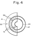
- FIG. 5 A second embodiment of the present invention is illustrated in Figs. 5 and 6.
- the apparatus includes a base plate 61, an outlet pipe 62, a flange 63 formed integral with the outlet pipe 62 on the outer wall thereof, and a fluted filter unit 64.
- the filter unit 64 comprises side wheels 65 and 66 on the upper and lower sides thereof, respectively, a filter cloth 67 folded into a fluted configuration and connected at its circumference, and a perforated support plate 68.
- Numeral 69 denotes a support equipped with a nut, 70 a blind flange, and 71 a bolt.
- the bolt 71 fastens the blind flange 70 to the support and nut combination 69 and serves to fix the fluted filter unit 64 by pulling it against the flange 63.
- the base plate 61 is provided with orifices 72 and a cleaning air jetting passage 73 communicating with the orifices 72.
- a pipe 74 connects the passage 73 with a cleaning air inlet pipe 76 through an automatic valve 75.
- Numeral 77 designates a bolt hole provided in the base plate 61.
- the inclined lines shown at number 78 indicate the outermost boundary of the total cleaning air flow jetted from the orifices 72, which are flared downwardly and inclined inwardly to jet the air in the indicated region.
- the fluted filter cloth has an inner diameter d, an outer diameter D, and a height H.
- the treating flow rate per filter unit also is 1.5 m 3 /min (25,000 cm 3 /sec), the same as in the first embodiment, thereby facilitating a comparison of the two. While this embodiment has almost the same function and operates in almost the same manner as the first embodiment, there are certain distinctions which will now be set forth.
- the required filter cloth area of 7,500 cm may be obtained using a rectangular filter cloth which is 15 cm wide and 500 cm long.
- the opposing lateral (short) edges of the filter cloth are adhered to each other to form the filter cloth into a ring, which is then folded to form 50 flutes of a width of 5 cm each at right angles to the long sides of the cloth.
- This provides the fluted filter cloth 67 which is shown installed in the filter unit in Fig. 6.
- the wheels 65, 66 are disk-shaped members having a round hole provided at the center thereof.
- the area of the donut-shaped region of the outer diameter D and inner diameter d is 228 cm 2 , half of which (114 cm ) is the cross-sectional area of the passages for the cleaning air, which passages are defined by the spaces between the flutes of the filter cloth. This is 1/68 of the filter cloth area of 7,500 cm 2 .
- the cleaning operation is similar to that practiced in the first embodiment. Specifically, by momentarily opening and then closing the automatic valve 75, pressurized air from the inlet pipe 76 passes through the pipe 74 and jetting passage 73 and is jetted from the orifices 72 in the spread pattern indicated by the lines 78, whereby the air flows through the spaces between the flutes on the primary side of the filter cloth 67, thereby to clean the filter.
- the filter cake is cleaned off the filter cloth fully, without the filter cake continuing to build up and harden on the flutes of the filter, as in the conventional backwashing method.
- a layer of the filter cake forms in the usual fashion on each of the closely opposing surfaces on the primary side of the filter cloth in the narrow spaces between the neighboring flutes. Since the spaces become particularly narrow near the core of the filter, namely at the inner peripheral portion thereof, it is here that the filter cake layers on the adjacent flute surfaces draw near to each other. From observations of a cleaning cycle using the backwashing technique, it has been found that filter cake over only a limited area is peeled off and caused to fall since the force of the backwashing air is extremely weak, as mentioned earlier. This is similar to the situation experienced with the cylindrical type filter cloth.
- a fluted filter unit one characteristic of a fluted filter unit is that the impact of the jetted backwashing air causes each of the fluted portions to inflate on the secondary side, thereby narrowing the spaces between the fluted portions on the primary side. Following the instantaneous jetting of the cleaning air, the associated valve is closed, allowing the spaces between flutes to more or less return to their original condition. As the filtering and cleaning cycles are repeated, it has been observed that the mutually adjacent filter cake surfaces on the fluted portions are compressed, compacted and unified at the narrow spaces approximate the inner peripheral portion of the filter where the filter cake is particularly difficult to peel off.
- next filtering cycle particles are added to the portions between the filter cloth and the compressed, hardened filter cake and are themselves compressed by the action of the next backwashing cycle, until the inner peripheral portion of the filter cloth is eventually clogged with a hardened particulate mass.
- the filter cloth at his portion is no longer in its original condition and is urged toward the secondary side. Thenceforth, this portion of the filter obviously is completely incapable of performing filtration.
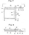
- FIG. 7 A third embodiment of the present invention is shown in Figs. 7 and 8.
- the apparatus includes a base plate 81 having bolt holes 82, an inlet pipe 83 connected to a pipe 85 by an automatic valve 84 for opening and closing the passage between the pipes, a pipe 8 6 for jetting cleaning air communicating with the pipe 85 and having a number of orifices 87, and a filter mounting member 88 provided on the base plate 81.
- Numeral 89 denotes an outlet hole, and 90 an outlet pipe communicating with the outlet hole 89.
- a filter cloth supporting rod 91 a filter cloth 92 and a packing 93.
- Character L indicates the width necessary for installing one filter unit.
- the filter unit is installed on the wall of a collecting vessel (not shown) by means of the base plate 81.
- the collecting vessel wall is provided with a rectangular opening one side of which is somewhat shorter than the distance between the bolt holes 82, thereby allowing the bolts passed through the bolt holes 82 to engage the collecting vessel wall.
- the length of the sides of the opening adjacent the abovementioned side is found by multiplying L by the number of filter units to be installed.
- the filter units are-arranged side-by-side with the filter cloth bags being spaced apart by L, the flat filter cloth surfaces of the filter units are held close together and in parallel, whereby a cleaning air passage of a small cross-sectional area is formed between adjacent ones of the flat filter surfaces. Cleaning air, jetted from the orifices 87 and accompanied by the peripheral air, passes through these passages at high speed and exits from the opposite side thereof, thereby cleaning the primary side of each filter cloth. Since the outermost filter units of the filter unit array will not have an adjacent filter cloth surface on one side thereof, a guide plate having the same shape as that of the filter cloths may be disposed at this location. Otherwise, the outermost filter cloths may be regarded as being non-active portions of the apparatus.
- the filter cloth is of great length as measured from the edge facing the orifices 87 to the opposite edge thereof, the effect of the cleaning air flow can be enhanced by providing a : guide plate opposite the rectangular base plates 81 for interconnecting the outermost edges of the filter cloths.
- the filter cloth may consist of a fabric, paper, unwoven fabric, wire mesh or the like.
- the filter member be of such type that the surface on the primary side thereof facing the open space utilize its fine porosity to collect fine particles or powders, and that the internal structure of the filter member, from the surface of its primary side to its secondary side, have passages through to the secondary side, which passages have an opening diameter substantially equal to or larger than the pore size of the primary side. Any filter member satisfying these requirements may be employed.
- the possible choices are (a) vertical, (b) horizontal and facing downwardly, (c) horizontal and facing upwardly, (d) inclined and facing downwardly and (e) inclined and facing upwardly.
- the critical point is to design cleaning air flow paths which direct the filter cake toward the bottom of the collecting vessel as the filter cake is removed in conjunction with the departure of the cleaning air from the terminus of each filter cloth, and to suitably decide the positions of the orifices and the direction of the jetted air relative to the filter cloth surface.
- the filter cloth may be of a cylindrical, hexagonal or any other multilateral configuration.
- the object of filtration is not limited to air, for the invention may be employed for filtering gases of all kinds.
Landscapes
- Chemical & Material Sciences (AREA)
- Chemical Kinetics & Catalysis (AREA)
- Physics & Mathematics (AREA)
- Geometry (AREA)
- Filtering Of Dispersed Particles In Gases (AREA)
Applications Claiming Priority (2)
| Application Number | Priority Date | Filing Date | Title |
|---|---|---|---|
| JP172948/81 | 1981-10-30 | ||
| JP56172948A JPS5876121A (ja) | 1981-10-30 | 1981-10-30 | フィルタの洗滌方法およびフィルタ装置 |
Publications (2)
| Publication Number | Publication Date |
|---|---|
| EP0078678A1 true EP0078678A1 (fr) | 1983-05-11 |
| EP0078678B1 EP0078678B1 (fr) | 1986-01-08 |
Family
ID=15951317
Family Applications (1)
| Application Number | Title | Priority Date | Filing Date |
|---|---|---|---|
| EP82305764A Expired EP0078678B1 (fr) | 1981-10-30 | 1982-10-29 | Procédé et dispositif pour nettoyer des filtres |
Country Status (4)
| Country | Link |
|---|---|
| US (1) | US4486201A (fr) |
| EP (1) | EP0078678B1 (fr) |
| JP (1) | JPS5876121A (fr) |
| DE (1) | DE3268454D1 (fr) |
Cited By (5)
| Publication number | Priority date | Publication date | Assignee | Title |
|---|---|---|---|---|
| EP0357931A1 (fr) * | 1988-09-09 | 1990-03-14 | Krupp Koppers GmbH | Filtre à pression de gaz |
| EP0269810A3 (fr) * | 1986-10-15 | 1990-04-04 | Rudolf Martin Schmid | Filtre à auto-nettoyage pour des milieux gazéiformes, son procede et son execution |
| EP0506171A1 (fr) * | 1991-03-29 | 1992-09-30 | COFISE S.p.A. | Dispositif pneumatique pour le nettoyage de filtres à air |
| US5458665A (en) * | 1993-07-12 | 1995-10-17 | A. Ahlstrom Corporation | Apparatus for filtering gases |
| WO2007149388A3 (fr) * | 2006-06-19 | 2008-05-22 | Donaldson Co Inc | Systèmes de filtre à air à jet pulsé; composants; et, procédés |
Families Citing this family (18)
| Publication number | Priority date | Publication date | Assignee | Title |
|---|---|---|---|---|
| US4553986A (en) * | 1984-11-13 | 1985-11-19 | Westinghouse Electric Corp. | Filtering system and method of using same |
| FI86965C (fi) * | 1991-04-04 | 1992-11-10 | Ahlstroem Oy | Foerfarande och anordning foer rening av roekgaser |
| US5108473A (en) * | 1991-06-19 | 1992-04-28 | Hayden Sr Robert E | Dust collector with atmospheric backflush |
| CA2516007C (fr) | 2003-02-11 | 2014-09-02 | Donaldson Company, Inc. | Agencements de filtres a air, elements de filtre pret a l'usage et procedes |
| US20110197556A1 (en) | 2004-11-02 | 2011-08-18 | Baldwin Filters, Inc. | Filter element |
| US20090205445A1 (en) * | 2008-02-14 | 2009-08-20 | Raether Thomas D | Method for selecting a filter element for a dust collector |
| JP5149089B2 (ja) * | 2008-07-04 | 2013-02-20 | 大陽日酸株式会社 | 集塵機におけるフィルタの洗浄方法 |
| DE102014009886A1 (de) * | 2014-07-04 | 2016-01-07 | Mann + Hummel Gmbh | Filterelement zur Filtrierung von Medien |
| EP2525891B1 (fr) | 2010-01-22 | 2020-10-07 | Donaldson Company, Inc. | Systèmes de filtre à air à jet pulsé, agencements de soupape d'évacuation; composants de filtres à air; et procédés associés |
| DE102010001678A1 (de) | 2010-02-08 | 2011-08-11 | Alfred Kärcher GmbH & Co. KG, 71364 | Kehrmaschine |
| JP2011183267A (ja) * | 2010-03-05 | 2011-09-22 | Fujikura Ltd | 集塵装置 |
| EP2734098B1 (fr) | 2011-07-22 | 2016-09-07 | Alfred Kärcher GmbH & Co. KG | Balayeuse avec conteneur sous pression pour le nettoyage du filtre |
| JP6234265B2 (ja) * | 2014-02-17 | 2017-11-22 | 裕男 水島 | フィルタユニット及び集塵機 |
| US10682597B2 (en) | 2016-04-14 | 2020-06-16 | Baldwin Filters, Inc. | Filter system |
| CN107149818B (zh) * | 2017-06-22 | 2018-04-17 | 江苏蓝天环保集团股份有限公司 | 一种底部防晃式除尘滤袋 |
| CN111195453B (zh) * | 2020-02-11 | 2022-05-17 | 湖南鑫保天环保设备科技有限公司 | 一种工业袋式除尘设备 |
| EP3888516A1 (fr) * | 2020-04-01 | 2021-10-06 | Hilti Aktiengesellschaft | Nettoyage du filtre en fonction des besoins |
| TWI910920B (zh) * | 2024-11-20 | 2026-01-01 | 信佑機械工程有限公司 | 濾布袋清洗方法 |
Citations (3)
| Publication number | Priority date | Publication date | Assignee | Title |
|---|---|---|---|---|
| US3095289A (en) * | 1960-09-02 | 1963-06-25 | Cottrell Res Inc | Gas cleaning apparatus |
| DE2146746A1 (de) * | 1971-09-18 | 1973-03-22 | Standard Filterbau Gmbh | Abreinigungsvorrichtung fuer taschenoder schlauchfilter |
| GB2060433A (en) * | 1979-10-10 | 1981-05-07 | Simon Barrow Ltd | Gas filter |
Family Cites Families (7)
| Publication number | Priority date | Publication date | Assignee | Title |
|---|---|---|---|---|
| GB992290A (en) * | 1963-02-13 | 1965-05-19 | Dust Control Equipment Ltd | Improvement in gas filtering apparatus |
| CH437213A (fr) * | 1964-07-01 | 1967-06-15 | Doucet Charles | Installation de filtration d'un fluide |
| US3816977A (en) * | 1971-10-04 | 1974-06-18 | Aerodyne Dev Corp | Method and apparatus for bag collection of dirt |
| FR2196188B1 (fr) * | 1972-07-28 | 1977-01-14 | Air Ind | |
| US4007026A (en) * | 1975-08-13 | 1977-02-08 | Fmc Corporation | Compact dust filter system |
| US4082523A (en) * | 1977-02-04 | 1978-04-04 | Josef Pausch | Filter bag cleaning apparatus |
| US4306888A (en) * | 1980-01-24 | 1981-12-22 | Phillips Petroleum Company | Method for filtering dust |
-
1981
- 1981-10-30 JP JP56172948A patent/JPS5876121A/ja active Granted
-
1982
- 1982-10-29 US US06/437,684 patent/US4486201A/en not_active Expired - Lifetime
- 1982-10-29 EP EP82305764A patent/EP0078678B1/fr not_active Expired
- 1982-10-29 DE DE8282305764T patent/DE3268454D1/de not_active Expired
Patent Citations (3)
| Publication number | Priority date | Publication date | Assignee | Title |
|---|---|---|---|---|
| US3095289A (en) * | 1960-09-02 | 1963-06-25 | Cottrell Res Inc | Gas cleaning apparatus |
| DE2146746A1 (de) * | 1971-09-18 | 1973-03-22 | Standard Filterbau Gmbh | Abreinigungsvorrichtung fuer taschenoder schlauchfilter |
| GB2060433A (en) * | 1979-10-10 | 1981-05-07 | Simon Barrow Ltd | Gas filter |
Cited By (11)
| Publication number | Priority date | Publication date | Assignee | Title |
|---|---|---|---|---|
| EP0269810A3 (fr) * | 1986-10-15 | 1990-04-04 | Rudolf Martin Schmid | Filtre à auto-nettoyage pour des milieux gazéiformes, son procede et son execution |
| EP0357931A1 (fr) * | 1988-09-09 | 1990-03-14 | Krupp Koppers GmbH | Filtre à pression de gaz |
| EP0506171A1 (fr) * | 1991-03-29 | 1992-09-30 | COFISE S.p.A. | Dispositif pneumatique pour le nettoyage de filtres à air |
| US5458665A (en) * | 1993-07-12 | 1995-10-17 | A. Ahlstrom Corporation | Apparatus for filtering gases |
| WO2007149388A3 (fr) * | 2006-06-19 | 2008-05-22 | Donaldson Co Inc | Systèmes de filtre à air à jet pulsé; composants; et, procédés |
| US8404021B2 (en) | 2006-06-19 | 2013-03-26 | Donaldson Company, Inc. | Pulse jet air cleaner system; components; and, methods |
| EP2708273A1 (fr) * | 2006-06-19 | 2014-03-19 | Donaldson Company, Inc. | Systèmes de filtre à air à jet pulsé; composants et procédés |
| US9108135B2 (en) | 2006-06-19 | 2015-08-18 | Donaldson Company, Inc. | Pulse jet air cleaner systems; components; and, methods |
| US9757673B2 (en) | 2006-06-19 | 2017-09-12 | Donaldson Company, Inc. | Pulse jet air cleaner systems, components, and, methods |
| US10512870B2 (en) | 2006-06-19 | 2019-12-24 | Donaldson Company, Inc. | Pulse jet air cleaner systems, components, and, methods |
| US10967320B2 (en) | 2006-06-19 | 2021-04-06 | Donaldson Company, Inc. | Pulse jet air cleaner systems; components; and, methods |
Also Published As
| Publication number | Publication date |
|---|---|
| JPS5876121A (ja) | 1983-05-09 |
| DE3268454D1 (en) | 1986-02-20 |
| JPH0139807B2 (fr) | 1989-08-23 |
| EP0078678B1 (fr) | 1986-01-08 |
| US4486201A (en) | 1984-12-04 |
Similar Documents
| Publication | Publication Date | Title |
|---|---|---|
| EP0078678B1 (fr) | Procédé et dispositif pour nettoyer des filtres | |
| US4578092A (en) | Method and apparatus for improving the operation of a dust collector | |
| US4661131A (en) | Backflushed air filters | |
| US3421295A (en) | Gas filtering apparatus | |
| US4278454A (en) | Filter apparatus with reverse flow cleaning | |
| US5062867A (en) | Method of retrofitting a dust collecting apparatus | |
| US3716971A (en) | Method of filtering | |
| US7918907B2 (en) | Cleaning nozzle for dust collector | |
| US3798878A (en) | Filter cleaning apparatus | |
| EP0339229A1 (fr) | Filtre à air avec lavage à contre-courant | |
| US4666472A (en) | Dust collector with deflector means | |
| JPH0685847B2 (ja) | 急速開放多噴流放出弁 | |
| US4247313A (en) | Gas-particulate separator with pulse-jet cleanable filter elements | |
| US4536200A (en) | Gas filter apparatus and method of filtering | |
| EP0354667A3 (fr) | Appareil pour nettoyer les cartouches de filtre d'un système de pulvérisation de poudre | |
| US4789387A (en) | Dust collector | |
| CA1069001A (fr) | Filtre a air muni d'un dispositif de prefiltrage a lames | |
| JPH06226169A (ja) | 粉末スプレイコーティング装置 | |
| CN1143331A (zh) | 织物过滤器 | |
| JPH0420655B2 (fr) | ||
| US3960526A (en) | Particle separating apparatus | |
| US5338339A (en) | Apparatus and method for removing resinated wood particles from an air stream | |
| JP2000107533A (ja) | バグフィルタ装置 | |
| RU2063786C1 (ru) | Сопловый фильтр | |
| CN210631880U (zh) | 一种过滤均流一体式除尘器 |
Legal Events
| Date | Code | Title | Description |
|---|---|---|---|
| PUAI | Public reference made under article 153(3) epc to a published international application that has entered the european phase |
Free format text: ORIGINAL CODE: 0009012 |
|
| AK | Designated contracting states |
Designated state(s): CH DE FR GB LI |
|
| 17P | Request for examination filed |
Effective date: 19831018 |
|
| GRAA | (expected) grant |
Free format text: ORIGINAL CODE: 0009210 |
|
| AK | Designated contracting states |
Designated state(s): CH DE FR GB LI |
|
| ET | Fr: translation filed | ||
| REF | Corresponds to: |
Ref document number: 3268454 Country of ref document: DE Date of ref document: 19860220 |
|
| PLBE | No opposition filed within time limit |
Free format text: ORIGINAL CODE: 0009261 |
|
| STAA | Information on the status of an ep patent application or granted ep patent |
Free format text: STATUS: NO OPPOSITION FILED WITHIN TIME LIMIT |
|
| 26N | No opposition filed | ||
| PGFP | Annual fee paid to national office [announced via postgrant information from national office to epo] |
Ref country code: GB Payment date: 20010423 Year of fee payment: 19 |
|
| PGFP | Annual fee paid to national office [announced via postgrant information from national office to epo] |
Ref country code: CH Payment date: 20010424 Year of fee payment: 19 |
|
| PGFP | Annual fee paid to national office [announced via postgrant information from national office to epo] |
Ref country code: FR Payment date: 20010427 Year of fee payment: 19 |
|
| PGFP | Annual fee paid to national office [announced via postgrant information from national office to epo] |
Ref country code: DE Payment date: 20010430 Year of fee payment: 19 |
|
| PG25 | Lapsed in a contracting state [announced via postgrant information from national office to epo] |
Ref country code: GB Free format text: LAPSE BECAUSE OF NON-PAYMENT OF DUE FEES Effective date: 20011029 |
|
| PG25 | Lapsed in a contracting state [announced via postgrant information from national office to epo] |
Ref country code: LI Free format text: LAPSE BECAUSE OF NON-PAYMENT OF DUE FEES Effective date: 20011031 Ref country code: CH Free format text: LAPSE BECAUSE OF NON-PAYMENT OF DUE FEES Effective date: 20011031 |
|
| REG | Reference to a national code |
Ref country code: GB Ref legal event code: IF02 |
|
| REG | Reference to a national code |
Ref country code: CH Ref legal event code: PL |
|
| GBPC | Gb: european patent ceased through non-payment of renewal fee |
Effective date: 20011029 |
|
| PG25 | Lapsed in a contracting state [announced via postgrant information from national office to epo] |
Ref country code: FR Free format text: LAPSE BECAUSE OF NON-PAYMENT OF DUE FEES Effective date: 20020628 |
|
| PG25 | Lapsed in a contracting state [announced via postgrant information from national office to epo] |
Ref country code: DE Free format text: LAPSE BECAUSE OF NON-PAYMENT OF DUE FEES Effective date: 20020702 |
|
| REG | Reference to a national code |
Ref country code: FR Ref legal event code: ST |