EP0079181A1 - Vakuum-Überwachungsgerät für Vakuum-Schalter und seine Verwendung - Google Patents
Vakuum-Überwachungsgerät für Vakuum-Schalter und seine Verwendung Download PDFInfo
- Publication number
- EP0079181A1 EP0079181A1 EP82305761A EP82305761A EP0079181A1 EP 0079181 A1 EP0079181 A1 EP 0079181A1 EP 82305761 A EP82305761 A EP 82305761A EP 82305761 A EP82305761 A EP 82305761A EP 0079181 A1 EP0079181 A1 EP 0079181A1
- Authority
- EP
- European Patent Office
- Prior art keywords
- vacuum
- vacuum interrupter
- interrupter
- monitor
- antenna
- Prior art date
- Legal status (The legal status is an assumption and is not a legal conclusion. Google has not performed a legal analysis and makes no representation as to the accuracy of the status listed.)
- Granted
Links
- 239000004020 conductor Substances 0.000 claims abstract description 31
- 238000001514 detection method Methods 0.000 claims abstract description 16
- 238000009413 insulation Methods 0.000 claims description 14
- 230000002159 abnormal effect Effects 0.000 claims description 10
- 239000002184 metal Substances 0.000 claims description 9
- 229910052751 metal Inorganic materials 0.000 claims description 9
- 229910052573 porcelain Inorganic materials 0.000 claims description 9
- 239000003990 capacitor Substances 0.000 claims description 6
- 230000035945 sensitivity Effects 0.000 claims description 5
- 238000012545 processing Methods 0.000 claims description 3
- 238000010586 diagram Methods 0.000 description 6
- 238000000034 method Methods 0.000 description 4
- 238000002474 experimental method Methods 0.000 description 3
- RYGMFSIKBFXOCR-UHFFFAOYSA-N Copper Chemical compound [Cu] RYGMFSIKBFXOCR-UHFFFAOYSA-N 0.000 description 2
- XEEYBQQBJWHFJM-UHFFFAOYSA-N Iron Chemical compound [Fe] XEEYBQQBJWHFJM-UHFFFAOYSA-N 0.000 description 2
- 229910052802 copper Inorganic materials 0.000 description 2
- 239000010949 copper Substances 0.000 description 2
- 230000007423 decrease Effects 0.000 description 2
- 230000006866 deterioration Effects 0.000 description 2
- 238000004519 manufacturing process Methods 0.000 description 2
- 238000010943 off-gassing Methods 0.000 description 2
- 230000003287 optical effect Effects 0.000 description 2
- 238000012360 testing method Methods 0.000 description 2
- 125000000391 vinyl group Chemical group [H]C([*])=C([H])[H] 0.000 description 2
- 229920002554 vinyl polymer Polymers 0.000 description 2
- 241000180177 Listrocephalos corona Species 0.000 description 1
- 230000003213 activating effect Effects 0.000 description 1
- 230000015556 catabolic process Effects 0.000 description 1
- 239000000919 ceramic Substances 0.000 description 1
- 230000003111 delayed effect Effects 0.000 description 1
- 238000000151 deposition Methods 0.000 description 1
- 230000005684 electric field Effects 0.000 description 1
- 239000000835 fiber Substances 0.000 description 1
- 239000011521 glass Substances 0.000 description 1
- 150000002500 ions Chemical class 0.000 description 1
- 229910052742 iron Inorganic materials 0.000 description 1
- 239000000463 material Substances 0.000 description 1
- 238000005259 measurement Methods 0.000 description 1
- 238000012986 modification Methods 0.000 description 1
- 230000004048 modification Effects 0.000 description 1
- 238000012544 monitoring process Methods 0.000 description 1
- 239000013307 optical fiber Substances 0.000 description 1
- 230000000644 propagated effect Effects 0.000 description 1
- 229910001220 stainless steel Inorganic materials 0.000 description 1
- 239000010935 stainless steel Substances 0.000 description 1
- 238000010998 test method Methods 0.000 description 1
Images


Classifications
-
- H—ELECTRICITY
- H01—ELECTRIC ELEMENTS
- H01H—ELECTRIC SWITCHES; RELAYS; SELECTORS; EMERGENCY PROTECTIVE DEVICES
- H01H33/00—High-tension or heavy-current switches with arc-extinguishing or arc-preventing means
- H01H33/60—Switches wherein the means for extinguishing or preventing the arc do not include separate means for obtaining or increasing flow of arc-extinguishing fluid
- H01H33/66—Vacuum switches
- H01H33/668—Means for obtaining or monitoring the vacuum
-
- G—PHYSICS
- G01—MEASURING; TESTING
- G01M—TESTING STATIC OR DYNAMIC BALANCE OF MACHINES OR STRUCTURES; TESTING OF STRUCTURES OR APPARATUS, NOT OTHERWISE PROVIDED FOR
- G01M3/00—Investigating fluid-tightness of structures
- G01M3/40—Investigating fluid-tightness of structures by using electric means, e.g. by observing electric discharges
-
- G—PHYSICS
- G01—MEASURING; TESTING
- G01R—MEASURING ELECTRIC VARIABLES; MEASURING MAGNETIC VARIABLES
- G01R31/00—Arrangements for testing electric properties; Arrangements for locating electric faults; Arrangements for electrical testing characterised by what is being tested not provided for elsewhere
- G01R31/327—Testing of circuit interrupters, switches or circuit-breakers
- G01R31/3271—Testing of circuit interrupters, switches or circuit-breakers of high voltage or medium voltage devices
- G01R31/3275—Fault detection or status indication
Definitions
- the present invention relates generally to a vacuum monitor for detecting poor vacuum pressure within a vacuum interrupter, and more specifically to a vacuum monitor which can produce an alarm or warning indication when vacuum pressure within a vacuum interrupter is abnormally increasing.
- the term "increasing" is used here in the sense of the vacuum becoming more imperfect.
- a vacuum interrupter for use with an electric power circuit has a normal circuit interruption performance when pressure of vacuum within its evacuated envelope is kept below 10-4 Torr (Torricelli).
- Torricelli 10-4 Torr
- the pressure of vacuum sometimes increases and the circuit interruption performance deteriorates, because of, for instance, outgassing from materials used for the interrupter or slow leakage of air (air may leak through cracks caused by undue mechanical stresses or through welded or insufficiently brazed junction portions).
- the small contact spacing will no longer be able to sustain a high voltage applied to the contacts; arcs and flashovers will occur; white hot arc will burn the contact surfaces and may melt the vacuum envelope and other parts of the vacuum interrupter.
- the invention as claimed provides:
- the vacuum monitor for a vacuum interrupter comprises an antenna disposed near conductive material of the vacuum interrupter for receiving electromagnetic wave signals generated by electric discharge caused in accordance with a prebreakdown voltage depending upon Paschen's law when vacuum pressure increases within the vacuum interrupter and a detection section connected to the antenna for electrically processing the electromagnetic wave signals received by the antenna in order to indicate poor vacuum pressure within a vacuum interrupter.
- the reference numeral 1 denotes a typical vacuum interrupter, the evacuated envelope of which comprises two tubular insulating housings 2 made of glass or ceramics and hermetically joined to each other by two metallic tubes 3 with a disk 4 sandwiched therebetween, and a pair of metallic end caps 7 also hermetically joined to the tubular insulating housing 2, respectively, with a metallic tube 6 joined hermetically on either opposite side (upper and lower sides) of the insulating housing 2.
- a metallic contact rods 8 and 9 At the center of the respective end caps 7, there are disposed two conductive contact rods 8 and 9.
- the fixed conductive contact rod 8 is hermetically joined at its upper end to the upper metallic end cap 7.
- a fixed contact 10 is fixedly brazed to the lower end of the fixed conductive contact rod 8 and an external connection conductor 11 is joined to the upper end of the fixed conductive contact rod 8.
- the movable conductive contact rod 9 is movably joined to the lower end cap 7 through a metal bellows 12 so as to be freely movable in the axial direction of the envelope without destroying a vacuum within the envelope.
- a movable contact 13 is fixedly brazed to the upper end of the movable conductive contact rod 9, and a slide contact 14 is slidably fitted to the lower end of the movable contact rod 9.
- the numeral 15 denotes another external connection conductor for mounting the slide contact 14.
- the numeral 16 denotes a tubular main shield disposed at the intermediate portion of the envelope for preventing metal vapor, generated from the fixed and movable contacts 10 and 13 when they are opened or closed, from depositing onto the inner surfaces of the tubular insulating housings 2.
- the numeral 17 denotes a pair of upper and lower auxiliary shields. Further, in Fig. 1, when a high supply voltage is connected to the external conductor 11, a power circuit is connected to the other external conductor 15.
- the vacuum interrupter 1 is operated by driving .the movable contact 13 up and down to close and open an electric power circuit connected thereto.
- the two contacts are closed, current flows from the upper external connection conductor 11 to the lower external connection conductor 15 or vice versa, through the path of the fixed contact rod 8, the fixed contact 10, the movable contact 13 and the movable contact rod 9.
- Power circuit interruption is effected by driving the movable contact 13 downward so as to be separated from the fixed contact 10 by an appropriate operating apparatus (not shown).
- a vacuum monitor 20 having an antenna 21 according to the present invention is disposed near the vacuum interrupter 1 for detecting poor vacuum pressure within the interrupter envelope.
- Fig. 2(A) is an equivalent circuit diagram of the vacuum interrupter shown in Fig. 1, in which the two contacts thereof are kept opened.
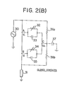
- Fig. 2(B) is the same circuit diagram, in which the two contacts thereof are kept closed.
- the reference numeral 30 denotes a power supply for a power circuit to be interrupted by a vacuum interrupter;
- the reference numeral 31 denotes a load for the power circuit.
- the reference numeral 32 denotes an insulation resistance existing between the fixed contact 10 including the fixed contact rod 8 and the main shield 16;
- the numeral 33 denotes a stray capacitance existing between the fixed contact 10 including the fixed contact rod 8 and the main shield 16.
- the reference numeral 34 denotes an insulation resistance existing between the movable contact 13 including the movable contact rod 9 and the main shield 16; the numeral 35 denotes a stray capacitance existing between the movable contact 13 including the movable contact rod 9 and the main shield 16.
- the reference numerals 36a and 36b denote insulation resistances in the two tubular insulating housings 2, respectively; the numeral 37 denotes a stray capacitance existing between the main shield 16 and the ground.
- the reference numeral 38 denotes an insulation resistance existing between the fixed and movable contacts 10 and 13 and the numeral 39 denotes a stray capacitance existing between the two contacts 10 and 13, in the case where the two contacts are opened.
- Figs. 2(A) and 2(B) only the insulation resistances are represented in the form of variable resistor. The reason is as follows: since the dielectric constant in a vacuum is almost the same as that in the air, the stray capacitances 33, 35, 37, and 39 do not change even when the vacuum pressure within the vacuum interrupter deteriorates, that is, increases. On the other hand, the insulation resistances 32, 34, and 38 change in accordance with a prebreakdown voltage depending upon Paschen's law when the vacuum pressure deteriorates. Generally, Paschen's law indicates that breakdown voltage in a vacuum decreases with increasing products of vacuum pressure (Torr) and contact gap distance (mm) to a certain point of inflection and then increases with the increasing products after exceeding the inflection point.
- Torr vacuum pressure
- mm contact gap distance
- the insulation resistance 38, 32 or 34 drops gradually over a long time (e.g. 2 to 3 years) and therefor strange electric dark current will flow therebetween, thus a kind of strange electromagnetic wave being emitted. Since the electromagnetic wave generated by the above-mentioned potential difference (between A and B or between A and C or B and C) tends to be propagated in conductive material connected to the vacuum interrupter and to be emitted therefrom, it is possible to indirectly check poor vacuum pressure within a vacuum interrupter by placing an antenna near a conductive material of the interrupter in order to detect the electromagnetic wave signals generated by strange electric dark discharge when the vacuum pressure increases within the vacuum interrupter.
- the potential V 1 is equal to the potential V 2 when the two contacts are kept closed and the floating potential V 3 changes according to the stray capacitance 37 which is usually determined by the grounded condition.
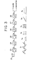
- Fig. 3 shows a schematic block diagram of the vacuum monitor 20 according to the present invention shown in Fig. 1.
- the vacuum monitor 20 comprises an antenna 21 and an antenna cable 22, and a detection section 20 including a buffer amplifier 23, a band-pass filter 24, an amplifier 25, a first comparator 26, an integrator or a counter 27 and a second comparator 28.
- the antenna 21 detects the electromagnetic wave signals existing near a conductive material of a vacuum interrupter.
- the buffer amplifier 23 having a high input impedance amplifies the signal received by the antenna 21 and outputs the signal S 1 as shown in Fig. 3.
- the signal S1 indicates that the electromagnetic wave signals are superimposed as ripples upon a commercial frequency of, for instance, 50 or 60 Hz.
- the band-pass filter 24 passes only the frequency components of 2 to 20 kHz from the signal S1 (the commercial frequency components are, of course eliminated) and outputs signal S 2 . That is to say, this band-pass filter 24 serves to eliminate frequency components of 2 kHz or less from the signal S 1 . This is because rotary machines, transformers, power measurement instruments, etc. often generate signals including higher harmonics of 2 kHz or less.
- the amplifier 25 amplifies the filtered signal S2 to the corresponding signal S 3 .
- the first comparator 26 compares this amplified signal S 3 with a predetermined reference voltage level and outputs a signal S 4 whenever the amplified signal S3 exceeds the reference level.
- the integrator (or a counter) 27 continually integrates or counts the number of the signal S 4 and outputs the corresponding signal S 5 .
- the second comparator 28 compares the integrated or counted signal S 5 with another predetermined reference value and outputs a signal S 6 when the signal S 5 exceeds the reference level. This signal S 6 outputted from the second comparator 28 is used for producing an alarm or for activating an indicator to show poor vacuum pressure or that vacuum pressure is abnormally increasing within the interrupter.
- the above-mentioned vacuum monitor 20 can be used by fixedly installing it (as a fixed-type vacuum monitor) or by movably approaching it (as a portable-type vacuum monitor) near a vacuum interrupter.
- the buffer amplifier 23 is disconnected electrically from the bandpass filter 24 and is connected optically by using an appropriate optical signal transmitting means such as a light emitting diode, a phototransistor, optical fibers, etc.
- the antenna portion when used as a portable-type vacuum monitor, is electrically separated from the detection section by an insulating rod.
- an insulating rod On top of the insulating rod there are mounted the antenna and a E-O (electrooptical) converter, and received electromagnetic wave signals are inputted through optical 'fiber to the detection section mounted on the bottom side of the rod in order to prevent electric shock. Further, in monitoring vacuum pressure, only the antenna is brought near the vacuum interrupter to be monitored.
- Fig. 4 (A) shows the wave-form of the voltage signal developing across the two contacts when the vacuum pressure within the vacuum interrupter is normal (e.g. 10 -4 Torr or less).
- Fig. 4(B) shows the wave-form of the signal received by the antenna when the vacuum pressure is normal.
- a commercial frequency e.g. 50 or 60 Hz
- the signal received by the antenna is roughly a sine wave upon which signals including higher harmonics of 2 kHz or less are superimposed.
- These superimposed signals may be generated for rotary machines, transformers, measuring devices, etc. installed near the vacuum interrupter or in or near the electric power circuit to which the vacuum interrupter is connected.
- Fig. 5(A) shows the wave-form of the voltage signal developing across the two contacts when the vacuum pressure is abnormal (e.g. 10 -3 Torr or more).
- Fig. 5(B) shows the wave-form of the electromagnetic wave signals received by the antenna when the vacuum pressure is abnormal.
- the frequency components of the electromagnetic wave signals received by the antenna ranges from 10 to 14 kHz when the electrostatic capacitance between the load and the ground is 0.0042 pF, from 2 to 8 k H z when the capacitance is 0.05 uF, and from 2 to 20 kHz when the capacitance is 0.2 ⁇ F or more.
- the detection sensitivity can be improved by connecting a capacitance of about 0.25 ⁇ F on the load side of the vacuum interrupter, in order to stably detect the electromagnetic wave signals caused by abnormal poor vacuum pressure.
- the detected signal voltage outputted from the amplifier 25 is about 0.3V.
- the reason why the detected signal voltage is low when the two contacts are closed, in comparison with that obtained when the two contacts are opened, may be due to the following fact: when the two contacts are closed, since electric discharge is generated only between the fixed and movable contact rods 8 and 9 including the fixed and movable contacts 10 and 13 and the main shield 16, the insulation resistance (parallel connection of 32 and 34) existing therebetween may be greater than the insulation resistance 38 existing between two contacts, and therefore the electric discharge energy obtained when the two contacts are closed may be smaller than that obtained when the two contacts are opened.
- Fig. 6 shows a second embodiment of the vacuum monitor according to the present invention.
- a loop antenna 21a is provided for the vacuum monitor in place of a rod antenna 21 shown in Fig. 1.
- the equivalent length of this loop antenna 21a is almost the same as that of the rod antenna 21. That is to say, the diameter of this loop antenna is about 10 cm and the straight portion thereof is about 5 cm.
- FIG. 6 shows a vacuum interrupter in which the two contacts thereof are kept closed, in order to clearly illustrate that it is also possible to detect poor vacuum pressure even when the contacts are kept closed and when a high voltage is kept applied to a power circuit through a vacuum interrupter; in other words, under hot-line condition.
- ultra-high-voltage class vacuum interrupters e.g. 66 kV or more
- insulating medium such as insulation oil or gas
- Fig. 7 shows an example of these cases.
- the reference numeral 30 denotes a tank filled with an insulating medium, which is made of metal plate such as iron or stainless steel plates.
- the reference numeral 31 denotes a porcelain bushing through which a conductor is passed and connected to the fixed contact rod.
- the numerals 11 and 15 denote external connection conductors.
- the numeral 32 denotes a capacitor connected between the movable contact side conductor and the tank in order to increase detection sensitivity when the two contacts are kept closed.
- the antenna 21 of the vacuum monitor 20 it is preferable to place the antenna 21 of the vacuum monitor 20 near the porcelain bushing 31. This is because the vacuum interrupter is housed within a tank and the tank is grounded.
- This capacitor 32 of 0.25 pF is effective especially when vacuum pressure is required to check in the state when the two contacts are kept closed. This is because the field strength of the electromagnetic wave signals caused by electric discharge between the two contact rods including two contacts and the main shield is relatively weak.
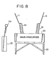
- Fig. 8 shows an example of detecting poor vacuum pressure within a vacuum interrupter housed within a tank 30 together with other operating devices.
- the vacuum interrupter incorporated with other operating devices such as a motor is called a vacuum circuit breaker herein.
- the tank 30 is mounted on a stand frame 33.
- the first porcelain bushing 34 is used for insulating from the tank 30 a first external connection conductor 11 to which a power supply is connected
- the second porcelain bushing 35 is used for insulating from the tank 30 a second external connection conductor 15 to which a load is connected.
- Fig. 9 shows an example of detecting poor vacuum pressure within a vacuum interrupter housed within a tank 30, that is, within a single-phase vacuum switch gear.
- a porcelain bushing 34 is provided for insulating from the tank 30 an external connection conductor 11 to which a power supply is connected.
- the antenna 21 or 21a of the vacuum monitor 20 is placed near the porcelain bushing 34.
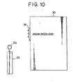
- Fig. 10 shows an example of detecting poor vacuum pressure within a vacuum interrupter housed within a tank 30 of a vacuum switch gear in which various power elements or devices are housed together.
- a three-phase external terminal 36 is provided for connecting external devices thereto.
- the antenna 21 or 21a of the vacuum monitor 20 is placed near the three-phase terminal 36 attached to the outside surface of the tank 30.
- the vacuum monitor according to the present invention is applicable to almost all the ordinary vacuum interrupters now in use, excluding the ones which are perfectly ground-shielded, and advantageously can check the'vacuum pressure while a voltage is kept applied to the interrupter, that is, under hot-line condition. Further, since a commercial domestic power supply (100 or 200V) or battery cells can be used as the power supply for the monitor, it is possible to realize a small-sized lightweight portable-type vacuum monitor. Furthermore, the more the contact spacing, the higher the detection sensitivity ' of the monitor. This .is because the electric dark discharge is generated at a lower voltage in dependence upon Paschen's law. Therefore, it is possible to check vacuum pressure within such a range as wide as 10-3 to 100 Torr.
- the vacuum monitor since the vacuum pressure within a vacuum interrupter can be checked, on the basis of the electromagnetic wave signals generated by electric discharge existing between the two contacts in the case when the two contacts are kept opened or between the two contact rods including the contacts and the main shield in the case when the two contacts are kept closed in accordance with a prebreakdown voltage depending upon Paschen's law, by the use of an antenna placed near the conductive material of the interrupter and since the antenna-received signal including only higher harmonics of 2 to 20 kHz is amplified and compared with a predetermined reference value to output an alarm signal, it is possible to realize a very convenient, low-priced, small-sized vacuum monitor for a vacuum interrupter.
Landscapes
- Physics & Mathematics (AREA)
- General Physics & Mathematics (AREA)
- Measuring Fluid Pressure (AREA)
Applications Claiming Priority (6)
| Application Number | Priority Date | Filing Date | Title |
|---|---|---|---|
| JP173887/81 | 1981-10-30 | ||
| JP173890/81 | 1981-10-30 | ||
| JP56173887A JPS5893128A (ja) | 1981-10-30 | 1981-10-30 | 真空しや断器の真空度監視装置 |
| JP17389081A JPS5894727A (ja) | 1981-10-30 | 1981-10-30 | 真空しや断器の真空度監視装置 |
| JP12674/82 | 1982-01-29 | ||
| JP1267482A JPS58129338A (ja) | 1982-01-29 | 1982-01-29 | 真空しや断器の真空度監視装置 |
Publications (2)
| Publication Number | Publication Date |
|---|---|
| EP0079181A1 true EP0079181A1 (de) | 1983-05-18 |
| EP0079181B1 EP0079181B1 (de) | 1986-03-26 |
Family
ID=27279934
Family Applications (1)
| Application Number | Title | Priority Date | Filing Date |
|---|---|---|---|
| EP82305761A Expired EP0079181B1 (de) | 1981-10-30 | 1982-10-29 | Vakuum-Überwachungsgerät für Vakuum-Schalter und seine Verwendung |
Country Status (3)
| Country | Link |
|---|---|
| US (1) | US4547769A (de) |
| EP (1) | EP0079181B1 (de) |
| DE (1) | DE3270153D1 (de) |
Cited By (9)
| Publication number | Priority date | Publication date | Assignee | Title |
|---|---|---|---|---|
| EP0098523A3 (en) * | 1982-07-05 | 1985-10-09 | Kabushiki Kaisha Meidensha | Vacuum monitor for vacuum interrupter |
| GB2168198A (en) * | 1984-11-21 | 1986-06-11 | Ass Elect Ind | Terminating vacuum switches |
| DE4310619A1 (de) * | 1992-04-02 | 1993-10-14 | Fuji Electric Co Ltd | Verfahren und Apparat zum Nachweisen einer Reduktion im Vakuumgrad eines Vakuumschaltventils |
| EP0758794A1 (de) * | 1995-08-10 | 1997-02-19 | Siemens Aktiengesellschaft | Vorrichtung zur Überwachung des Vakuums eines Vakuumschalters |
| EP1763049B1 (de) * | 2005-09-13 | 2016-08-24 | Hitachi, Ltd. | Vakuumschaltanlage |
| US9570263B2 (en) | 2013-06-11 | 2017-02-14 | Supergrid Institute Sas | Vacuum switching assembly |
| CN111916305A (zh) * | 2020-09-07 | 2020-11-10 | 广东电网有限责任公司广州供电局 | 一种高压真空断路器中真空度监测方法和装置 |
| CN113745049A (zh) * | 2021-08-27 | 2021-12-03 | 西安交通大学 | 一种真空灭弧室内真空度监测方法及系统 |
| CN114659706A (zh) * | 2022-05-19 | 2022-06-24 | 季华实验室 | 真空度检测方法、装置、电子设备、存储介质及系统 |
Families Citing this family (27)
| Publication number | Priority date | Publication date | Assignee | Title |
|---|---|---|---|---|
| DE3702009C2 (de) * | 1987-01-22 | 1994-11-10 | Siemens Ag | Einrichtung zur Überwachung des Vakuums einer Vakuumschaltröhre |
| JPH04204270A (ja) * | 1990-11-30 | 1992-07-24 | Toshiba Corp | ガス絶縁開閉装置の部分放電検出装置 |
| DE19526393C2 (de) * | 1995-07-19 | 1998-11-19 | Siemens Ag | Verfahren zum Vakuumnachweis in betriebsmäßig eingebauten Vakuumschaltröhren |
| JP3799924B2 (ja) * | 2000-01-11 | 2006-07-19 | 株式会社日立製作所 | 電力用遮断器および発電所電気回路装置 |
| US6418791B1 (en) | 2000-03-22 | 2002-07-16 | Abb Technology Ag | System and method for acoustic integrity monitoring |
| JP3628244B2 (ja) * | 2000-08-28 | 2005-03-09 | 株式会社日立製作所 | 部分放電検出方法 |
| JP2002184275A (ja) * | 2000-12-12 | 2002-06-28 | Meidensha Corp | 真空遮断器の真空度監視方法とその装置 |
| US7111983B2 (en) * | 2004-04-13 | 2006-09-26 | Reliance Electric Technologies, Llc | Temperature detection method and apparatus for inverter-driven machines |
| US7302854B2 (en) * | 2004-05-18 | 2007-12-04 | Jennings Technology | Method and apparatus for the detection of high pressure conditions in a vacuum-type electrical device |
| US7215299B2 (en) * | 2004-10-12 | 2007-05-08 | Eaton Corporation | Antenna protected from dielectric breakdown and sensor or switchgear apparatus including the same |
| US7148677B2 (en) * | 2005-02-15 | 2006-12-12 | Eaton Corporation | Vacuum circuit interrupter including circuit monitoring leakage or loss of vacuum and method of monitoring a vacuum interrupter for leakage or loss of vacuum |
| US7383733B2 (en) * | 2005-09-30 | 2008-06-10 | Jennings Technology | Method and apparatus for the sonic detection of high pressure conditions in a vacuum switching device |
| US7253630B1 (en) * | 2006-09-05 | 2007-08-07 | Gaton Corporation | Electro-optical voltage sensor circuit monitoring leakage or loss of vacuum of a vacuum interrupter and vacuum circuit interrupter including the same |
| FR2906194B1 (fr) * | 2006-09-21 | 2008-12-19 | Alstom Transport Sa | Vehicule ferroviaire equipe de contacteurs, procede de commande et utilisation de ces contacteurs |
| ES2340750B1 (es) * | 2008-04-23 | 2011-05-16 | Universidad Carlos Iii De Madrid | Sensor inductivo con aislamiento galvanico para la deteccion y medidade pulsos de corriente de alta frecuencia. |
| FR2968827B1 (fr) * | 2010-12-09 | 2012-12-21 | Schneider Electric Ind Sas | Dispositif de detection de la perte de vide dans un appareil de coupure a vide et appareil de coupure a vide comportant un tel dispositif |
| US9335378B2 (en) | 2011-12-13 | 2016-05-10 | Finley Lee Ledbetter | Flexible magnetic field coil for measuring ionic quantity |
| US9759773B2 (en) | 2011-12-13 | 2017-09-12 | Finley Lee Ledbetter | System and method to predict a usable life of a vacuum interrupter in the field |
| US9053881B2 (en) * | 2012-08-24 | 2015-06-09 | Schneider Electric USA, Inc. | Arc detection with resistance to nuisance activation through light subtraction |
| CA2941432A1 (en) | 2014-05-12 | 2015-11-19 | Cooper Technologies Company | Vacuum loss detection |
| FR3026554B1 (fr) * | 2014-09-25 | 2018-04-06 | Schneider Electric Industries Sas | Dispositif surveillance de la qualite du vide d'un disjoncteur a vide |
| GB2556520B (en) * | 2015-06-15 | 2021-10-13 | Vacuum Interrupters Inc | System and method to predict a useable life of a vacuum interrupter in the field |
| CA3033769A1 (fr) | 2019-02-14 | 2020-08-14 | Daniel Pineau | Detecteur de decharge partielle et methode associee |
| EP4031845B1 (de) * | 2019-09-20 | 2025-03-05 | Inficon AG | Verfahren zu bestimmung eines drucks und drucksensor |
| CN112017907A (zh) * | 2020-08-13 | 2020-12-01 | 黄山学院 | 一种真空断路器真空度劣化非接触探测方法及其预警装置 |
| CN113488351B (zh) * | 2021-06-29 | 2024-04-30 | 广东电网有限责任公司广州供电局 | 一种高压断路器真空度在线监测实验装置及方法 |
| CN115575804B (zh) * | 2022-08-29 | 2023-09-15 | 海南电网有限责任公司电力科学研究院 | 一种用于断路器的放电故障模拟装置 |
Citations (4)
| Publication number | Priority date | Publication date | Assignee | Title |
|---|---|---|---|---|
| US3403297A (en) * | 1966-03-17 | 1968-09-24 | Gen Electric | Vacuum-type circuit interrupter with pressure-monitoring means |
| US3882380A (en) * | 1972-02-10 | 1975-05-06 | F C Robinson & Partners Limite | High voltage component testing systems |
| US4021702A (en) * | 1974-04-02 | 1977-05-03 | Siemens Aktiengesellschaft | Arrangement for detecting deficient operational capability of vacuum switching vessels |
| US4159446A (en) * | 1978-02-21 | 1979-06-26 | General Electric Company | Acoustic diagnostic system for contacts in power distribution systems |
Family Cites Families (9)
| Publication number | Priority date | Publication date | Assignee | Title |
|---|---|---|---|---|
| NL289145A (de) * | 1962-03-22 | |||
| US3594754A (en) * | 1968-01-26 | 1971-07-20 | Westinghouse Electric Corp | Pressure measurement arrangements for a vacuum-type circuit interrupter |
| SE410067B (sv) * | 1974-04-02 | 1979-09-17 | Siemens Ag | Anordning for detektering av bristande driftsduglighet for vakuum-brytkamrar |
| US4159466A (en) * | 1976-08-03 | 1979-06-26 | Troyonics, Inc. | Burglar alarm system |
| US4103291A (en) * | 1976-09-30 | 1978-07-25 | Howe Francis M | Leak sensor and indicating system for vacuum circuit interrupters |
| JPS53125881A (en) * | 1977-04-11 | 1978-11-02 | Toshiba Corp | Vacuum detection of non-constact type |
| JPS5856429B2 (ja) * | 1978-05-11 | 1983-12-14 | 三菱電機株式会社 | 真空度測定装置 |
| DE3174794D1 (en) * | 1980-03-24 | 1986-07-17 | Meidensha Electric Mfg Co Ltd | Vacuum circuit interrupter system |
| US4440995A (en) * | 1981-01-19 | 1984-04-03 | Westinghouse Electric Corp. | Vacuum circuit interrupter with on-line vacuum monitoring apparatus |
-
1982
- 1982-10-29 EP EP82305761A patent/EP0079181B1/de not_active Expired
- 1982-10-29 DE DE8282305761T patent/DE3270153D1/de not_active Expired
- 1982-10-29 US US06/437,678 patent/US4547769A/en not_active Expired - Fee Related
Patent Citations (4)
| Publication number | Priority date | Publication date | Assignee | Title |
|---|---|---|---|---|
| US3403297A (en) * | 1966-03-17 | 1968-09-24 | Gen Electric | Vacuum-type circuit interrupter with pressure-monitoring means |
| US3882380A (en) * | 1972-02-10 | 1975-05-06 | F C Robinson & Partners Limite | High voltage component testing systems |
| US4021702A (en) * | 1974-04-02 | 1977-05-03 | Siemens Aktiengesellschaft | Arrangement for detecting deficient operational capability of vacuum switching vessels |
| US4159446A (en) * | 1978-02-21 | 1979-06-26 | General Electric Company | Acoustic diagnostic system for contacts in power distribution systems |
Non-Patent Citations (2)
| Title |
|---|
| Patent Abstracts of Japan Vol. 2, no. 156, 26 December 1978 Page 10190E78 * |
| Patent Abstracts of Japan Vol. 4, No.5, 16 January 1980 Page 157E165 * |
Cited By (13)
| Publication number | Priority date | Publication date | Assignee | Title |
|---|---|---|---|---|
| EP0098523A3 (en) * | 1982-07-05 | 1985-10-09 | Kabushiki Kaisha Meidensha | Vacuum monitor for vacuum interrupter |
| GB2168198A (en) * | 1984-11-21 | 1986-06-11 | Ass Elect Ind | Terminating vacuum switches |
| DE4310619A1 (de) * | 1992-04-02 | 1993-10-14 | Fuji Electric Co Ltd | Verfahren und Apparat zum Nachweisen einer Reduktion im Vakuumgrad eines Vakuumschaltventils |
| US5399973A (en) * | 1992-04-02 | 1995-03-21 | Fuji Electric Co., Ltd. | Method and apparatus for detecting a reduction in the degree of vacuum of a vacuum valve while in operation |
| EP0758794A1 (de) * | 1995-08-10 | 1997-02-19 | Siemens Aktiengesellschaft | Vorrichtung zur Überwachung des Vakuums eines Vakuumschalters |
| US5739419A (en) * | 1995-08-10 | 1998-04-14 | Siemens Aktiengesellschaft | Apparatus for monitoring the vacuum of a vacuum switch |
| EP1763049B1 (de) * | 2005-09-13 | 2016-08-24 | Hitachi, Ltd. | Vakuumschaltanlage |
| US9570263B2 (en) | 2013-06-11 | 2017-02-14 | Supergrid Institute Sas | Vacuum switching assembly |
| CN111916305A (zh) * | 2020-09-07 | 2020-11-10 | 广东电网有限责任公司广州供电局 | 一种高压真空断路器中真空度监测方法和装置 |
| CN113745049A (zh) * | 2021-08-27 | 2021-12-03 | 西安交通大学 | 一种真空灭弧室内真空度监测方法及系统 |
| CN113745049B (zh) * | 2021-08-27 | 2022-07-12 | 西安交通大学 | 一种真空灭弧室内真空度监测方法及系统 |
| CN114659706A (zh) * | 2022-05-19 | 2022-06-24 | 季华实验室 | 真空度检测方法、装置、电子设备、存储介质及系统 |
| CN114659706B (zh) * | 2022-05-19 | 2022-08-02 | 季华实验室 | 真空度检测方法、装置、电子设备、存储介质及系统 |
Also Published As
| Publication number | Publication date |
|---|---|
| US4547769A (en) | 1985-10-15 |
| EP0079181B1 (de) | 1986-03-26 |
| DE3270153D1 (en) | 1986-04-30 |
Similar Documents
| Publication | Publication Date | Title |
|---|---|---|
| EP0079181B1 (de) | Vakuum-Überwachungsgerät für Vakuum-Schalter und seine Verwendung | |
| US4510441A (en) | Electric field detector | |
| US5399973A (en) | Method and apparatus for detecting a reduction in the degree of vacuum of a vacuum valve while in operation | |
| EP0036760B1 (de) | Vakuum-Schalter-System | |
| US4163130A (en) | Vacuum interrupter with pressure monitoring means | |
| CN102543564A (zh) | 检测真空断路装置中的真空损失的设备及其真空断路装置 | |
| US10199183B2 (en) | Vacuum-insulated switch enabling testing of the vacuum, switch assembly, and testing method | |
| GB2212282A (en) | Foreseeing deterioration in vacuum interrupters | |
| US4553139A (en) | Vacuum monitor for vacuum interrupter | |
| US3594754A (en) | Pressure measurement arrangements for a vacuum-type circuit interrupter | |
| EP0040918B1 (de) | Vakuumschalter mit einem Drucküberwachungssystem | |
| KR920008836B1 (ko) | 진공차단기용 진공모니터 | |
| KR860001784B1 (ko) | 진공차단기용 진공도 감시장치 | |
| KR101172750B1 (ko) | 진공차단기용 전류차단기구의 부분방전 측정장치 및 방법 | |
| JP2885233B2 (ja) | 真空バルブ形開閉装置の真空度低下検出装置 | |
| KR860000841Y1 (ko) | 진공 차단기의 압력 감시 장치 | |
| JPH0792481B2 (ja) | ガス絶縁密閉電器の電圧および部分放電検出装置 | |
| JPH0432488B2 (de) | ||
| JPH03205716A (ja) | 真空バルブ形開閉装置の真空度低下検出装置 | |
| JPS59175524A (ja) | 真空しや断器の真空度監視装置 | |
| KR102603638B1 (ko) | 진공차단기의 진공도 감시를 위한 부분 방전 측정 센서 및 이를 적용한 진공차단기 | |
| KR860000842Y1 (ko) | 진공 차단기의 진공도 감시 장치 | |
| JPS63186512A (ja) | 縮小形開閉装置の異常検出装置 | |
| JPS645648B2 (de) | ||
| JP2006337357A (ja) | 電圧検出装置 |
Legal Events
| Date | Code | Title | Description |
|---|---|---|---|
| PUAI | Public reference made under article 153(3) epc to a published international application that has entered the european phase |
Free format text: ORIGINAL CODE: 0009012 |
|
| AK | Designated contracting states |
Designated state(s): CH DE FR GB IT LI NL SE |
|
| 17P | Request for examination filed |
Effective date: 19830912 |
|
| GRAA | (expected) grant |
Free format text: ORIGINAL CODE: 0009210 |
|
| ITF | It: translation for a ep patent filed | ||
| AK | Designated contracting states |
Kind code of ref document: B1 Designated state(s): CH DE FR GB IT LI NL SE |
|
| ET | Fr: translation filed | ||
| REF | Corresponds to: |
Ref document number: 3270153 Country of ref document: DE Date of ref document: 19860430 |
|
| PLBE | No opposition filed within time limit |
Free format text: ORIGINAL CODE: 0009261 |
|
| STAA | Information on the status of an ep patent application or granted ep patent |
Free format text: STATUS: NO OPPOSITION FILED WITHIN TIME LIMIT |
|
| 26N | No opposition filed | ||
| PGFP | Annual fee paid to national office [announced via postgrant information from national office to epo] |
Ref country code: SE Payment date: 19911011 Year of fee payment: 10 |
|
| ITTA | It: last paid annual fee | ||
| PGFP | Annual fee paid to national office [announced via postgrant information from national office to epo] |
Ref country code: NL Payment date: 19911031 Year of fee payment: 10 |
|
| PG25 | Lapsed in a contracting state [announced via postgrant information from national office to epo] |
Ref country code: SE Effective date: 19921030 |
|
| PG25 | Lapsed in a contracting state [announced via postgrant information from national office to epo] |
Ref country code: NL Effective date: 19930501 |
|
| NLV4 | Nl: lapsed or anulled due to non-payment of the annual fee | ||
| PGFP | Annual fee paid to national office [announced via postgrant information from national office to epo] |
Ref country code: FR Payment date: 19940916 Year of fee payment: 13 |
|
| PGFP | Annual fee paid to national office [announced via postgrant information from national office to epo] |
Ref country code: CH Payment date: 19940930 Year of fee payment: 13 |
|
| PGFP | Annual fee paid to national office [announced via postgrant information from national office to epo] |
Ref country code: GB Payment date: 19941003 Year of fee payment: 13 |
|
| PGFP | Annual fee paid to national office [announced via postgrant information from national office to epo] |
Ref country code: DE Payment date: 19941212 Year of fee payment: 13 |
|
| EUG | Se: european patent has lapsed |
Ref document number: 82305761.7 Effective date: 19930510 |
|
| PG25 | Lapsed in a contracting state [announced via postgrant information from national office to epo] |
Ref country code: GB Effective date: 19951029 |
|
| PG25 | Lapsed in a contracting state [announced via postgrant information from national office to epo] |
Ref country code: LI Effective date: 19951031 Ref country code: CH Effective date: 19951031 |
|
| REG | Reference to a national code |
Ref country code: CH Ref legal event code: PL |
|
| GBPC | Gb: european patent ceased through non-payment of renewal fee |
Effective date: 19951029 |
|
| PG25 | Lapsed in a contracting state [announced via postgrant information from national office to epo] |
Ref country code: FR Effective date: 19960628 |
|
| PG25 | Lapsed in a contracting state [announced via postgrant information from national office to epo] |
Ref country code: DE Effective date: 19960702 |
|
| REG | Reference to a national code |
Ref country code: FR Ref legal event code: ST |