EP0080519B1 - Procédé et machine pour plier des affiches - Google Patents
Procédé et machine pour plier des affiches Download PDFInfo
- Publication number
- EP0080519B1 EP0080519B1 EP81109910A EP81109910A EP0080519B1 EP 0080519 B1 EP0080519 B1 EP 0080519B1 EP 81109910 A EP81109910 A EP 81109910A EP 81109910 A EP81109910 A EP 81109910A EP 0080519 B1 EP0080519 B1 EP 0080519B1
- Authority
- EP
- European Patent Office
- Prior art keywords
- tube
- folding
- rollers
- poster
- folding machine
- Prior art date
- Legal status (The legal status is an assumption and is not a legal conclusion. Google has not performed a legal analysis and makes no representation as to the accuracy of the status listed.)
- Expired
Links
- 238000000034 method Methods 0.000 title description 8
- 239000000463 material Substances 0.000 description 4
- 230000004888 barrier function Effects 0.000 description 3
- 238000005096 rolling process Methods 0.000 description 3
- 230000001154 acute effect Effects 0.000 description 2
- 230000003247 decreasing effect Effects 0.000 description 2
- 229920003023 plastic Polymers 0.000 description 2
- 238000011161 development Methods 0.000 description 1
- 230000018109 developmental process Effects 0.000 description 1
- 229920002457 flexible plastic Polymers 0.000 description 1
- 230000005484 gravity Effects 0.000 description 1
Images

Classifications
-
- B—PERFORMING OPERATIONS; TRANSPORTING
- B65—CONVEYING; PACKING; STORING; HANDLING THIN OR FILAMENTARY MATERIAL
- B65H—HANDLING THIN OR FILAMENTARY MATERIAL, e.g. SHEETS, WEBS, CABLES
- B65H45/00—Folding thin material
- B65H45/12—Folding articles or webs with application of pressure to define or form crease lines
- B65H45/18—Oscillating or reciprocating blade folders
-
- B—PERFORMING OPERATIONS; TRANSPORTING
- B65—CONVEYING; PACKING; STORING; HANDLING THIN OR FILAMENTARY MATERIAL
- B65H—HANDLING THIN OR FILAMENTARY MATERIAL, e.g. SHEETS, WEBS, CABLES
- B65H19/00—Changing the web roll
- B65H19/22—Changing the web roll in winding mechanisms or in connection with winding operations
- B65H19/2238—The web roll being driven by a winding mechanism of the nip or tangential drive type
-
- B—PERFORMING OPERATIONS; TRANSPORTING
- B65—CONVEYING; PACKING; STORING; HANDLING THIN OR FILAMENTARY MATERIAL
- B65H—HANDLING THIN OR FILAMENTARY MATERIAL, e.g. SHEETS, WEBS, CABLES
- B65H29/00—Delivering or advancing articles from machines; Advancing articles to or into piles
- B65H29/006—Winding articles into rolls
- B65H29/008—Winding single articles into single rolls
-
- B—PERFORMING OPERATIONS; TRANSPORTING
- B65—CONVEYING; PACKING; STORING; HANDLING THIN OR FILAMENTARY MATERIAL
- B65H—HANDLING THIN OR FILAMENTARY MATERIAL, e.g. SHEETS, WEBS, CABLES
- B65H45/00—Folding thin material
- B65H45/12—Folding articles or webs with application of pressure to define or form crease lines
Definitions
- the invention relates to a folding machine according to the preamble of the main claim.
- Posters such as those stuck to poster pillars and billboards, often have large dimensions, which is why they are folded to a small size before being glued on. Folding the posters will make it much easier to stick them on. There is a requirement to fold the posters to a uniform size - for example, to a width of 14 cm. To achieve this, the posters, which can have lengths of 2 to 3 m, have to be folded several times.
- US-A-3 671 033 also describes a folding machine for plastic bags which has two roll-up devices which are arranged at a distance and between which the removal and folding station is arranged. The same disadvantages also occur here, which is why this machine is not suitable for quickly rolling up and folding posters.
- the invention has for its object to provide a folding machine for folding posters that enables a large number of folds at high working speed.
- the posters to be folded are wound up with a poster roll by the rollers arranged at a certain distance from the tube.
- the posters are inserted between the rollers and the tube in a narrow area that is not covered by rollers.
- the rotated rollers then guide the inserted poster around the tube, whereby the distance between the tube and the outer rollers can be very small, for example 1 cm.
- a pull-off device is arranged at the free end of the tube, which pulls the poster roll axially from the tube and feeds it to a folding device.
- the take-off device essentially has a pressure roller arranged in the tube and a transport roller located outside the tube, wherein the pressure roller can be pressed in the direction of the transport roller through a slot in the tube.
- the poster roll in between is pulled outwards.
- the folding machine according to the invention is preferably designed such that a folding device is arranged in the extension of the free end of the tube, which has two conveyor belts converging at an acute angle, which compresses the respective removed poster roll flat, and that pressure rollers are connected behind the conveyor belts, which are continuous , press the compressed poster firmly together.
- the entire folding process runs automatically, with the pressure rollers ensuring that sharp-edged folds are created.
- a folding knife can also be provided, which moves on a circular path from an upper position above the folded poster to a horizontal position and thereby grabs the posters coming from the printing rollers in the middle and through a V-shaped funnel. This creates an additional center fold that is perpendicular to the folds created by the pressure rollers.
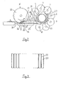
- the retractor 1 shown in Figure 1 consists essentially of an inner tube 2 and a plurality of rollers 3 which surround the tube 2 at a short distance.
- the rollers 3 are fastened to a plurality of drive axles 4 to 11 (FIG. 2) which are driven via associated gear wheels 12.
- the gear wheels 12 engage in a pinion 13 which is firmly connected to a further gear wheel 14.
- the gear 14 is driven by a toothed belt, not shown here.
- rollers 3 are arranged on each of their drive axles 4 to 11 with a small distance from one another, so that gaps arise between the rollers located on a drive axle.
- the rollers attached to an adjacent drive axle each engage in these gaps.
- the tube 2 is so closely surrounded by rollers 3 so that a poster inserted between rollers 3 and tube 2 cannot escape to the outside between the rollers.
- the tube 2 is firmly connected at one end 15 to the folding machine. In the illustrated embodiment, this connection is made via two supports 16 which are screwed to the frame 17 of the folding machine. The supports 16 completely surround the tube 2. The other end 18 of the tube 2 is self-supporting. As a result, a poster 19 (FIG. 2) wound up on the rollers 3 on the self-supporting end 18 can be pulled off the tube 2.
- a take-off device 20 which essentially consists of a transport roller 21 and a pressure roller 22.
- a poster wrapped between the transport roller 21 and the pressure roller 22 around the tube 2 is then pulled off the tube 2 in that the pressure roller 22 is pressed in the direction of the transport roller 21 through a slot 23 provided in the tube 2.
- the pressure roller 22 is actuated via a linkage 24 which is led out of the tube 2 at the other end 15. If the linkage 24 is pressed against a spring 25 in the direction of arrow a, the pressure roller 22 assumes the position shown here. The pressure roller 22 has this position during the reeling process.
- the linkage can be moved against the arrow direction a by the spring 25, whereby the pressure roller 22 is pressed through the slot 23 in the direction of the transport roller 21. Since the transport roller 21 rotates continuously in the specified direction, the poster roller located between the transport roller 21 and the pressure roller 22 is pulled off the tube 2 in the direction of the arrow b in this way.
- the poster roll then passes between two superposed conveyor belts 26, 27 which are part of a folding device which is described in more detail with reference to FIG. 4.
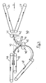
- FIG. 2 shows a simplified illustration of the side view of the retractor 1.
- the rollers 3 are arranged on several adjacent drive axes 4 to 11.
- the tube 2 is completely surrounded by the rollers 3, except for a narrow area, which can be referred to as the input area 28.
- the posters 19 are inserted between tube 2 and rollers 3.
- the Plalat 19 winds up to form a poster roller 29.
- the posters 19 are each passed over a deflection roller 31 under the roller 30.
- the roller 30 rotates continuously in the specified direction.
- Height-adjustable counter-pressure rollers 32 are arranged under the roller 30, which in their upper position press the poster 19 against the roller 30, so that the poster 19 is moved in the indicated direction c.
- the counter pressure rollers 32 are distributed over the length of the roller 30.
- the folding machine according to the invention has a guide device 33 so that a perfect paper feed is ensured.
- This essentially consists of guide rods 34 which engage in the recesses 35 provided on the roller 30.
- the design of the roller 30 with its recesses 35 is illustrated in FIG. 3.
- the guide rods 34 are designed such that their lower edge 36 is not arranged lower than the lowest point of the roller 30. In order that the engagement of a guide rod 34 in the associated recess 35 is clear, the roller 30 in FIG. 2 is at the corresponding point shown broken up.
- a rocker arm 37 which presses the poster roller 29 in the direction of the tube 2 on one side.
- the rocker arm 37 is rotatably mounted on an axis 38 attached outside its center of gravity, so that it presses against the poster roller 29 due to its own weight and the resulting torque.
- a lever not shown here, the rocker arm 37 can be brought into a position in which it no longer influences the diameter of the poster roller 29.
- the paper feed is preferably controlled via light barriers and stops, not shown here.
- a light barrier can be arranged in the specified area d, which detects the presence of a poster 19.
- a second light barrier can be provided in the area of the tube 2, which determines whether a poster roll 29 is in the reeling device.
- the paper feed can now be controlled via a control so that paper feed into the reel-up device is prevented when a poster is already in the reel-up device.
- the end of the reeling process can be controlled by means of a photo cell arranged in area d.
- the photocell recognizes the end of the poster of the poster pushed into the reel-up device and, after an adjustable time delay, causes the reel-up process to stop. This measure ensures that the poster end of the fully rolled up poster roll 29 is always in the same place at the end of the rolling up process.
- rollers 3 In order to enable the rollers 3 to be braked as suddenly as possible, it is advantageous if they consist of a material with the lowest possible mass. For this reason, the rollers 3 are preferably made of plastic.
- the sudden braking of the rollers 3 is obtained in that the drive shaft acting on the toothed belt is first uncoupled from the drive motor and braked immediately thereafter.
- the folding device 40 is shown.
- the poster roller 29 is pressed flat together by means of two conveyor belts 26, 27 tapering at an acute angle and passed under pressure between two pressure rollers 41, 42.
- the high pressure that the two pressure rollers 41, 42 exert on the pre-folded poster creates sharp-edged folds.
- a movable folding knife 43 is arranged behind the pressure rollers 41, 42. This folding knife 43 serves to fold the narrowly folded posters again in the middle. This center folding is necessary for posters with a large width.
- the poster passed between the pressure rollers 41 and 42 is passed under the vertical folding knife 43 until the Half of the poster has passed the folding knife in the dashed position. While the poster is being transported continuously, the folding knife 43 moves downward in accordance with the direction of the arrow indicated. As a result, the poster is pressed into the V-shaped funnel 44 and passed between two folding rollers 45. The folding knife 43 moves with the speed like the center of the poster.
- the bar 46, on which the folding knife 43 is fastened on the outside, moves in the direction indicated by the arrow at a decreasing angular velocity. The required decreasing angular velocity is achieved by a control cam, not shown here.
- the poster After the poster has passed through the folding rollers 45, it arrives at the exit of the folding device 40 via a third conveyor belt 47.
- Two further conveyor belts 48, 49 are also provided, between which posters of smaller dimensions are transported to the exit, since these smaller posters are in the middle do not need to be folded.
Landscapes
- Engineering & Computer Science (AREA)
- Mechanical Engineering (AREA)
- Folding Of Thin Sheet-Like Materials, Special Discharging Devices, And Others (AREA)
- Shaping Of Tube Ends By Bending Or Straightening (AREA)
Claims (5)
Priority Applications (3)
| Application Number | Priority Date | Filing Date | Title |
|---|---|---|---|
| EP81109910A EP0080519B1 (fr) | 1981-11-26 | 1981-11-26 | Procédé et machine pour plier des affiches |
| DE8181109910T DE3175074D1 (en) | 1981-11-26 | 1981-11-26 | Method and machine for folding posters |
| ES517180A ES517180A0 (es) | 1981-11-26 | 1982-11-06 | Maquina para el plegado de carteles. |
Applications Claiming Priority (1)
| Application Number | Priority Date | Filing Date | Title |
|---|---|---|---|
| EP81109910A EP0080519B1 (fr) | 1981-11-26 | 1981-11-26 | Procédé et machine pour plier des affiches |
Publications (2)
| Publication Number | Publication Date |
|---|---|
| EP0080519A1 EP0080519A1 (fr) | 1983-06-08 |
| EP0080519B1 true EP0080519B1 (fr) | 1986-08-06 |
Family
ID=8188036
Family Applications (1)
| Application Number | Title | Priority Date | Filing Date |
|---|---|---|---|
| EP81109910A Expired EP0080519B1 (fr) | 1981-11-26 | 1981-11-26 | Procédé et machine pour plier des affiches |
Country Status (3)
| Country | Link |
|---|---|
| EP (1) | EP0080519B1 (fr) |
| DE (1) | DE3175074D1 (fr) |
| ES (1) | ES517180A0 (fr) |
Families Citing this family (4)
| Publication number | Priority date | Publication date | Assignee | Title |
|---|---|---|---|---|
| US4479640A (en) * | 1983-07-22 | 1984-10-30 | Smith Carol E | Flat piece folding apparatus with variable speed, and method |
| DE3835023A1 (de) * | 1988-10-14 | 1990-04-19 | Gerhard Steidle | Aufwickelvorrichtung fuer papier-, textil- oder kunststoffbahnen |
| DE19629606C2 (de) * | 1996-07-23 | 2001-05-10 | Fillmatic Polsterindustriemasc | Vorrichtung zum Verpacken von mit einer Stoffhülle umgebenen Matratzen |
| CN117342332B (zh) * | 2023-07-14 | 2025-12-09 | 重庆两江联创电子有限公司 | 一种无尘布自动折叠装置及其控制方法 |
Family Cites Families (8)
| Publication number | Priority date | Publication date | Assignee | Title |
|---|---|---|---|---|
| DE276592C (fr) * | 1911-03-20 | |||
| GB862296A (en) * | 1958-04-02 | 1961-03-08 | Strachan & Henshaw Ltd | Improvements in or relating to apparatus for folding paper or like webs |
| DE1295304B (de) * | 1963-07-29 | 1969-05-14 | Lee Kennth Philip | Aufrollvorrichtung zum Aufwickeln von Bahnmaterial ohne Wickeltraeger |
| ES360183A1 (es) * | 1968-11-02 | 1970-06-16 | Sala Granell | Maquina para plegado de prendas de genero de punto. |
| US3711085A (en) * | 1970-08-28 | 1973-01-16 | E Bunch | Folder for business forms |
| US3671033A (en) * | 1970-11-23 | 1972-06-20 | Coast Machinery Inc | Machine and method for folding plastic bags and the like |
| FR2412485A2 (fr) * | 1977-12-26 | 1979-07-20 | Duflot Rene | Machine a plier des nappes de tissu, telles que des draps |
| US4180256A (en) * | 1978-06-28 | 1979-12-25 | Union Carbide Corporation | High speed bag folding machine |
-
1981
- 1981-11-26 DE DE8181109910T patent/DE3175074D1/de not_active Expired
- 1981-11-26 EP EP81109910A patent/EP0080519B1/fr not_active Expired
-
1982
- 1982-11-06 ES ES517180A patent/ES517180A0/es active Granted
Also Published As
| Publication number | Publication date |
|---|---|
| EP0080519A1 (fr) | 1983-06-08 |
| ES8400349A1 (es) | 1983-11-01 |
| DE3175074D1 (en) | 1986-09-11 |
| ES517180A0 (es) | 1983-11-01 |
Similar Documents
| Publication | Publication Date | Title |
|---|---|---|
| DE69421528T2 (de) | Umwickler mit Kontaktantrieb und Verfahren zur Minimalisierung des Schlupfes zwischen Antriebsrolle und Bahn | |
| EP0765809B1 (fr) | Procédé pour emballer un rouleau d'une bande de matériau | |
| EP3642144B1 (fr) | Dispositif permettant de distribuer un produit de rembourrage en forme de bobine à des fins d'emballage | |
| DE69702583T2 (de) | Verpackungsmaschine | |
| DE2600522C2 (fr) | ||
| EP0968919A1 (fr) | Procédé et dispositif d'enveloppement d'objets quadrangulaires avec un matériau d'emballage sous forme de bande | |
| DE2813100A1 (de) | Vorrichtung zum aufreihen von elektrischen bauelementen mit zwei fluchtenden anschlussdraehten zu einem gurt | |
| DE3315495C2 (de) | Vorrichtung zum Lagern von Papierbogen o.dgl. | |
| EP3440946A1 (fr) | Machine de l'industrie de traitement du tabac destinée à la production simultanée d'une pluralité de boudins | |
| EP0958734B1 (fr) | Presse à balles rondes pour produits agricoles | |
| EP0568844B1 (fr) | Dispositif et méthode pour enrouler un produit de l'imprimerie et pour envelopper le rouleau avec une enveloppe | |
| DE2451993B2 (de) | Etikettierstation | |
| DE4016484A1 (de) | Verpackungsvorrichtung fuer bahnrollen | |
| EP0080519B1 (fr) | Procédé et machine pour plier des affiches | |
| EP0313781A2 (fr) | Dispositif pour la fabrication de paquets portables tubulaires de produits d'imprimerie | |
| DE19612924A1 (de) | Vorrichtung zum automatischen Zuführen eines Endes einer Materialbahn | |
| DE4425662C1 (de) | Vorrichtung zum Quertrennen einer Papierbahn | |
| DE2446364A1 (de) | Vorrichtung zum transport von bogen, insbesondere an wellpappmaschinen | |
| DE2944089C2 (de) | Führungseinrichtung für einen Einwickelpapierstreifen bei einer Münzeneinwickelmaschine | |
| EP0481398B1 (fr) | Dispositif pour envelopper des balles dans une presse à balles | |
| DE3823705A1 (de) | Vorrichtung zum vereinzeln von zuschnitten aus einem stapel | |
| EP0221524B1 (fr) | Disposition pour le passage de feuilles | |
| DE19652448C9 (de) | Vorrichtung zum Verpacken einer Materialbahnrolle mit einer Verpackungsbahn | |
| EP0141394B1 (fr) | Dispositif pour enrouler des produits imprimés arrivant en formation imbriquée | |
| DE2139499C3 (de) | Vorrichtung zum Einwickeln zylindrischer Gegenstände, insbesondere Münzstapel |
Legal Events
| Date | Code | Title | Description |
|---|---|---|---|
| PUAI | Public reference made under article 153(3) epc to a published international application that has entered the european phase |
Free format text: ORIGINAL CODE: 0009012 |
|
| 17P | Request for examination filed |
Effective date: 19820929 |
|
| AK | Designated contracting states |
Designated state(s): BE DE FR GB IT LU |
|
| GRAA | (expected) grant |
Free format text: ORIGINAL CODE: 0009210 |
|
| AK | Designated contracting states |
Kind code of ref document: B1 Designated state(s): BE DE FR GB IT LU |
|
| PG25 | Lapsed in a contracting state [announced via postgrant information from national office to epo] |
Ref country code: IT Free format text: LAPSE BECAUSE OF FAILURE TO SUBMIT A TRANSLATION OF THE DESCRIPTION OR TO PAY THE FEE WITHIN THE PRESCRIBED TIME-LIMIT;WARNING: LAPSES OF ITALIAN PATENTS WITH EFFECTIVE DATE BEFORE 2007 MAY HAVE OCCURRED AT ANY TIME BEFORE 2007. THE CORRECT EFFECTIVE DATE MAY BE DIFFERENT FROM THE ONE RECORDED. Effective date: 19860806 Ref country code: FR Free format text: THE PATENT HAS BEEN ANNULLED BY A DECISION OF A NATIONAL AUTHORITY Effective date: 19860806 Ref country code: BE Effective date: 19860806 |
|
| REF | Corresponds to: |
Ref document number: 3175074 Country of ref document: DE Date of ref document: 19860911 |
|
| PG25 | Lapsed in a contracting state [announced via postgrant information from national office to epo] |
Ref country code: LU Free format text: LAPSE BECAUSE OF NON-PAYMENT OF DUE FEES Effective date: 19861130 |
|
| EN | Fr: translation not filed | ||
| GBPC | Gb: european patent ceased through non-payment of renewal fee | ||
| PG25 | Lapsed in a contracting state [announced via postgrant information from national office to epo] |
Ref country code: DE Effective date: 19870801 |
|
| PG25 | Lapsed in a contracting state [announced via postgrant information from national office to epo] |
Ref country code: GB Effective date: 19881122 |
|
| PLBE | No opposition filed within time limit |
Free format text: ORIGINAL CODE: 0009261 |
|
| STAA | Information on the status of an ep patent application or granted ep patent |
Free format text: STATUS: NO OPPOSITION FILED WITHIN TIME LIMIT |
|
| 26N | No opposition filed |