EP0083102A2 - Copiage et polycopiage - Google Patents
Copiage et polycopiage Download PDFInfo
- Publication number
- EP0083102A2 EP0083102A2 EP82112051A EP82112051A EP0083102A2 EP 0083102 A2 EP0083102 A2 EP 0083102A2 EP 82112051 A EP82112051 A EP 82112051A EP 82112051 A EP82112051 A EP 82112051A EP 0083102 A2 EP0083102 A2 EP 0083102A2
- Authority
- EP
- European Patent Office
- Prior art keywords
- recording material
- master
- support member
- sheet
- drum
- Prior art date
- Legal status (The legal status is an assumption and is not a legal conclusion. Google has not performed a legal analysis and makes no representation as to the accuracy of the status listed.)
- Withdrawn
Links
- 239000000463 material Substances 0.000 claims abstract description 78
- 238000012546 transfer Methods 0.000 claims abstract description 41
- 238000003384 imaging method Methods 0.000 claims abstract description 15
- 238000011161 development Methods 0.000 claims abstract description 8
- 238000004140 cleaning Methods 0.000 claims abstract description 6
- 238000002360 preparation method Methods 0.000 claims abstract description 3
- 230000004075 alteration Effects 0.000 claims description 3
- 238000000034 method Methods 0.000 description 6
- XLOMVQKBTHCTTD-UHFFFAOYSA-N Zinc monoxide Chemical compound [Zn]=O XLOMVQKBTHCTTD-UHFFFAOYSA-N 0.000 description 4
- 230000009471 action Effects 0.000 description 4
- 230000004044 response Effects 0.000 description 4
- 230000015572 biosynthetic process Effects 0.000 description 3
- 238000005286 illumination Methods 0.000 description 3
- 230000007246 mechanism Effects 0.000 description 3
- 230000003287 optical effect Effects 0.000 description 3
- 230000008569 process Effects 0.000 description 3
- AZDRQVAHHNSJOQ-UHFFFAOYSA-N alumane Chemical group [AlH3] AZDRQVAHHNSJOQ-UHFFFAOYSA-N 0.000 description 2
- 230000008901 benefit Effects 0.000 description 2
- 238000005513 bias potential Methods 0.000 description 2
- 238000001514 detection method Methods 0.000 description 2
- 238000010586 diagram Methods 0.000 description 2
- 230000000694 effects Effects 0.000 description 2
- 238000004088 simulation Methods 0.000 description 2
- 230000001360 synchronised effect Effects 0.000 description 2
- 239000011787 zinc oxide Substances 0.000 description 2
- 238000013459 approach Methods 0.000 description 1
- 238000004891 communication Methods 0.000 description 1
- 238000011109 contamination Methods 0.000 description 1
- 238000001816 cooling Methods 0.000 description 1
- 238000012937 correction Methods 0.000 description 1
- 230000001419 dependent effect Effects 0.000 description 1
- 230000009977 dual effect Effects 0.000 description 1
- 239000000203 mixture Substances 0.000 description 1
- 238000012544 monitoring process Methods 0.000 description 1
- 239000002245 particle Substances 0.000 description 1
- 230000002093 peripheral effect Effects 0.000 description 1
- 239000000843 powder Substances 0.000 description 1
- 238000004064 recycling Methods 0.000 description 1
- 230000009467 reduction Effects 0.000 description 1
- 239000011347 resin Substances 0.000 description 1
- 229920005989 resin Polymers 0.000 description 1
Images


Classifications
-
- G—PHYSICS
- G03—PHOTOGRAPHY; CINEMATOGRAPHY; ANALOGOUS TECHNIQUES USING WAVES OTHER THAN OPTICAL WAVES; ELECTROGRAPHY; HOLOGRAPHY
- G03G—ELECTROGRAPHY; ELECTROPHOTOGRAPHY; MAGNETOGRAPHY
- G03G15/00—Apparatus for electrographic processes using a charge pattern
- G03G15/22—Apparatus for electrographic processes using a charge pattern involving the combination of more than one step according to groups G03G13/02 - G03G13/20
- G03G15/228—Apparatus for electrographic processes using a charge pattern involving the combination of more than one step according to groups G03G13/02 - G03G13/20 the process involving the formation of a master, e.g. photocopy-printer machines
Definitions
- the present invention relates to apparatus for electrostatographic copying and fixed image duplicating of an original document.
- the present invention employs a roll of zinc oxide coated paper or other material remote from the drum, automatically feeds it towards the drum and clamps it onto the drum when demanded.
- the master can be used for copying and duplicating and it is a particular advantage that the same development unit or station can be used both for master development and for copy development.
- the drum or other support for the electrophotographic recording member runs. at different speeds depending upon whether the machine is master imaging, copying or duplicating and in order to facilitate this and to enable the parts of the machine to function in correctly timed sequence when the drum is accelerating or decelerating.
- Timing is preferably carried out by means of a pulse generator rotatable with the support and a decoder that forms part of the control unit that feeds signals denoting the number of cycles completed by the support and its position in the current cycle, selector logic units responding to this information to turn on their associated devices at the appropriate time.
- the invention provides an electrostatographic duplicator in which- an original document is duplicated by redeveloping a previously developed and fixed latent image, comprising in combination:
- the invention provides apparatus for electrostatographic reproduction of an original document by copying or fixed image duplicating including a supply spool that carries electrostatographic recording material in web form, means for advancing the recording material towards a rotatory support. member, means for severing the recording material into individual sheets, means for releasably clamping an individual sheet onto the support member, a master imaging station for forming a light image of an original document on the recording material on said support member, a development station for applying an insulating toner to an electrostatic latent image on the recording material, a master fixing station operable only when in the master fixing stage of the duplicating mode to fix a developed toner image from a master imaging cycle onto the sheet of recording material on the support member for-use in subsequent duplicating cycles, a transfer station operable to transfer an unfixed toner image from the recording member to a copy sheet during copying and to transfer a redeveloped toner image from the recording member during duplicating and control means selectively operable to cause the machine to perform copying
- a combined copier/duplicator of the present kind will normally work at a first speed when copying and at a second speed when duplicating. If copy sheet fixing is carried out by a heated roll fixing unit, then it is necessary for the fixing unit to_ adapt rapidly to different linear speeds of the copy sheet.
- the invention provides a combined electrostatographic copier and duplicator that forms copies by creating a light image of an original document on an electrostatographic recording member at each copy cycle and transfers a developed image to a copy sheet that is discharged at a first linear speed towards a fixing unit comprising a pair of rollers having deformable surfaces, at least one of said rollers being heated, the copy sheet passing between them in order to fix the toner image to the copy sheet and duplicates by forming further toner images on the recording member without creating a new light image and transferring the toner images to copy sheets that are discharged towards the fixing unit at a second linear speed higher than said first linear speed, said fixing unit having means operable to adjust the roller pressure between a first relatively low value for use when copying and a second higher value when duplicating whereby satisfactory toner fixing to the copy sheets at both said first and second speeds can be achieved without alteration of roller temperature.
- master material in the form of zinc oxide coated paper is held on a spool 1. Its leading edge passes between first and second pairs of feed rollers 2' and 2 between which there is a guillotine 3.
- the master material then passes a further roller and enters leading edge clamps 10 on the periphery of a rotary drum 4 which is rotated at the same peripheral speed as the linear speed of the master material.
- the drum 4 has a head clamp 10 and a tail clamp (not shown) for the cut sheet of master material each defined by a transversely directed recess or notch and a set of typically four clamping fingers.
- the head and tail clamping fingers are supported on common shafts having follower means and are arranged to be lifted as the drum rotates by means of a load cam operated by a solenoid or other suitable means. So when the load cam is in its working position, as the drum rotates the follower means travels over a raised sector thereby raising and lowering the clamping fingers.
- the feeding of the master sheet by rolle.rs 2' is synchronised with rotation of the drum so that the leading edge of the master sheet enters into the open head clamp at the appropriate position.
- master material continues to be drawn from the spool 1 until a required length has passed through the guillotine 3 which then operates.
- the free end of the master material is then drawn onto the drum and the tail clamping fingers are raised and lowered by the load cam in synchronised relationship to the arrival of the cut master sheet to clamp the trailing edge of the master sheet onto the drum and the transfer roller is raised to hold the master taut against the drum surface before the tail clamping fingers come down to retain it permanently in position.
- the tail clamping fingers Since the tail clamping fingers must rotate in the opposite direction to that of the head clamping fingers they are raised and lowered by similar follower means but via a pair of quadrant gears, the ratio of the quadrant gears being conveniently chosen so that the tail clamping fingers rotate approximately twice the angular movement of the head clamping fingers; this is necessary since the leading edge of the master sheet slides underneath the head clamping fingers whereas the trailing edge describes an involute arc when being clamped.
- a second solenoid operated cam 19 ( Figure 2) for master ejection is attached to the frame of the machine and has a lobed surface that the follower means follows when the master eject cam is in its working position.
- the master eject cam is displaced approximately 270° around the axis of the drum 4 with respect to the clamp 10 and may be used to eject a spent master from the drum.
- the head clamps pass the eject cam they are caused to open and two arms attached to the same shaft as the clamping fingers thrust the leading edge of the master sheet away from the drum, and the transfer roller is again raised to drive the ejected master forward into the exit chute.
- the master is then stripped from the drum and a master exit flap 19a raised to allow the spent master to pass down a disposal chute.
- the tail clamps are opened by the same cam so that the discarded master is free to fall into the chute.
- Synchronisation of the loading cycle is achieved by generating a series of clock pulses (256 per drum revolution) as the drum 4 rotates together with a counter reset pulse generated once per drum revolution. These pulses are generated by photo-electric sensors A and B ( Figure 2) and slotted discs (not shown). As the drum starts to rotate a counter receives a reset pulse and starts to count clock pulses. These pulses are used to control the sequence of operation of other parts.of the machine as more fully described below. This method of timing is a considerable advance on simple microswitches, timing cams or time delay systems because it allows the machine to operate at variable drum speeds and enables a correct timing sequence to be maintained when the drum is accelerated or decelerated.
- the master material When the master material is on the drum, it may be used for copying or duplicating purposes. All the components of the machine are employed in duplicating, whereas some of them are inoperative during copying, so it is convenient to describe the duplicating procedure first.
- the master sheet is electrically charged by a corona charging unit 12, and then imaged with a light image of a document to be copied.
- the document to be copied, supported on a platen driven by drive means 8 and illuminated by lamps 11 is conveyed past a strip lens array 25 synchronously with rotation of the drum 4 as described in R. W . Gundlach's US Patent Nos.3584950 and 3584952', in UK Patent Specification No.1200383 and in our copending UK Patent Application No.8136622.
- the imaged master sheet then passes to a development station 7 in which a two-component magnetic developer including particles of an insulating and charge retaining toner composition is applied to the latent electrostatic image on the master sheet by means of one or more magnetic brushes.
- the drum 4 is further rotated to pass the master sheet through a radiant master fuser 14 that fixes the toner image onto the master sheet.
- the condition of-master image fixing is desirably such that the fused toner resin possesses appropriate charge acceptance and decay properties and should desirably give a fixed master image that typically holds a surface charge of about -450v with a decay of not more than 15% after 0.5 seconds for at least 1000 charge/discharge cycles (see our copending UK Patent Application No.8123328).
- the drum 4 is required to travel relatively slowly, typically at about 12 r.p.m.
- the machine switches over to a duplicating cycle mode in which the drum 4 rotates considerably faster, typically at 30 to 100 r.p.m.
- the master sheet is recharged at the corona charging station 12, flood exposed by means of a strip lamp 15 and redeveloped with toner by means of the developer unit 7. Because of the insulating nature of the fused toner image on the master sheet, it retains its electrical charge on flood exposure, whereas the non-image areas being photoconductive are discharged by the action of lamp 15. The result is to create a new latent image of electrostatic charge in fixed toner image areas of the master sheet, and it is this new latent image that is redeveloped by the developer unit 7.
- Copy sheets are then advanced, synchronously with drum rotation, from a paper tray 6 by primary feed roller 16 and secondary feed rollers 17 to a transfer station where they pass between drum 4 and a transfer roller 9 where a bias potential is applied to the roller 9 to transfer the toner image onto the copy sheets.
- the electrical bias to roller 9 is arranged to be switched on only when the leading edge of each copy sheet has passed a predetermined distance beyond the transfer zone and is switched off when the trailing edge of the copy sheet has passed through the transfer zone.
- the master sheet on drum 4 is reused. Downstream of the developer unit 7 the toner image is transferred to copy sheets at transfer roller 9 without being fixed at fuser station 14 which is inoperative. And the platen drive 8 has to operate for each copy that is produced.
- the paper tray 6 is operated by. a paper raise and lower button 50 that controls drive motor 51 for the paper tray.
- An indicator and sensor device 52 is connected to a machine initialising logic unit 53 that forms part of a digital control system for the machine. Also connected- to the unit 53 are a toner sensor and indicator 54. Both sensor device 52 and unit 53 pass signals to device 55 that detects a lack of supplies and simulates copy 0 (final sheet) until further supplies are made.
- a power on-off switch 56 is connected via cover interlock sensor 57 to machine initialising logic unit 53 as also is a master roll located sensor 58 which senses when master material is not present in roll 1 and a platen position indicator and sensor 8'.
- a heat sensing and control unit 59 is in two-way communication with the initialising logic unit 53 so that the machine is not allowed to operate until the appropriate roller temperature has been attained.
- the logic unit 53 also communicates via paper misfeed logic unit 60 with paper misfeed sensors and indicator 61 and it outputs to standby indicator 62, to machine/operator interface logic unit 63, to OR gate 64 that enables master roll drive 2', to OR gate 65 that enables guillotine 3 and to the main motor 66 that drives the machine.
- the paper misfeed logic unit 60 communicates. with a decoder 67 for sensors A and B that outputs to a complete revolution data bus 68 and a partial revolution data bus 69.
- the data busses 68; 69 both communicate with a duplicating loop detector logic unit 70, a selector 71, a drum drive selection logic unit 72 that initiates high speed drive to drum 4 (low speed drive is initiated through logic unit 63), and a hot pressure fusing roll drive selection logic unit 73 that is also enabled by the loop detector logic unit 70. So the fuser rolls 5 will not start up until enabled by unit 53 and are thereafter controlled in operation by unit 73 that is enabled by detector 70 and is enabled by selector 73 that receives timing information by busses 68, 69.
- selection logic units in general respond to command signals to initiate operation of the respective device at the correct number and part revolution position of drum 4 signalled through busses 68, 69 to drive their associated device for an appropriate period.
- the developer unit 7 is controlled by selection logic unit 74 that is also controlled by the loop detector 70 and controls the drive to developer unit 7.
- the machine/operator interface logic unit 63 enables AND gate 75 that also receives an input from bias voltage unit 76 to apply a bias potential to the developer unit at an appropriate time.
- Selection logic units 77, 78 connected to busses 68, 69 respectively supply an input to OR gates 64, 65 that control the master roll drive 2' and guillotine 3.So these units can either be caused to operate when required to do so either in response to initialising logic 53 or to timing signals in busses 63,69 to feed a new master onto the drum to prepare for a copying and duplicating cycle.
- a selector logic unit 79 operates the solenoid for the feed cam 10 and selector logic unit 80 additionally connected to paper feed operation logic unit 8i effects raising and lowering of transfer roller 9 to and from its working position and additionally enables AND gate 82 to apply an EHT potential from unit 83 to roller 9 to bring about transfer of the developed toner image to the copy sheets.
- Logic unit 81 is also connected to paper misfeed sensor 61 and also duplicating loop detector 70. So a signal to selector logic unit 80 may cause the transfer roller 9 to be raised to its operative position during duplicating cycles and electrically biased at the appropriate time but to be disabled and lowered in the event of a paper misfeed.
- a first paper sensor 86 connected to a sensor logic unit 87 signals to units 55, 61 and 81 when a misfeed to primary feed rolls 17 takes place and additionally a 3-misfeeds indicator 88 is connected to the line from logic unit 87 to unit 55.
- Selector logic unit 84 for the drive units for primary and secondary paper feed drives 16, 17 is also connected to the duplicating loop detector unit 70 and also to the copy 0 detection or simulation unit 55.
- the platen drive 8 is connected to selector logic unit 89 and the vacuum unit 18 is connected to selector logic unit 90 which in addition to inputs from busses 68, 69 receives an enabling input from loop detector unit 70.
- the selector logic unit 91 for lamps 11 of the imaging station is connected thereto via a brightness control unit 92.
- Master eject cam and flap operating system 19 is operated via selection logic unit 93 and selector logic unit 94 enables AND gate 95 that connects EHT unit 96 to the corona unit 12.
- Master radiant fuser unit 14 is controlled by selector logic unit 97 and the flood illumination heaters and lamp 15 are controlled by selector logic unit 98 that is also electrically connected to loop detector unit 70 as shown.
- machine/operator interface logic unit 63 Connected to machine/operator interface logic unit 63 is master eject button and indicator 99 and duplicate button and indicator 100, the copy 0 detector or simulator unit 55 also being connected to the indicator 100 as shown.
- a keyboard entry unit 102 having a 4-digit copy counter and display is electrically connected to loop detection logic unit 70, copy 0 detector or simulation unit 55 and logic unit 63. Between logic unit 71 and logic unit 63 is a master fitted sensor and indicator unit 103.
- the machine is controlled from a range of input signals from a user accessible front panel having the power on/off switch 56; a master eject indicator button 99, the copy or duplicate indicator and button 100, keyboard by which the number of copies/duplicates required can be entered (part of 102) and a stop button not shown, and also from the two sensors A and B that are located on the drum drive mechanism and respectively define drum top dead centre for each revolution (sensor A) and the number of steps that the drum has moved from its top dead centre position (sensor B). The position count is reset to zero every time the drum 4 passes the top dead centre position.
- the main motor 66 starts, turning the cleaning brush 20 and the hot pressure fuser rollers 5 and also commencing to heat these up.
- the machine initialising logic initiates no further action for a short period eg. of 0.5 second duration in order that internal power supplies may stabilise.
- a master roll located sensor checks then that the free end of master roll 1 is correctly located in the nip of guillotine 3. If not, logic unit 53 signals OR gate 64 to drive the master roll drive 2' a short distance, after which it signals OR gate 65 to bring about operation of the guillotine to correctly locate the edge of the master material.
- selector 89 causes the platen drive to advance platen 8 and selector 91 turns on the lamps 11.
- the platen 8 advances synchronously with drum 4 and a light image of an original document placed thereon is projected onto the master sheet through optical system 13.
- the master has previously been charged by corona unit 12 enabled by selector 94 and gate 95 and the master bearing the resulting charged image passes through the developer unit 7, which deposits toner on the master.
- Selector 80 causes transfer roller 9 to be lowered to prevent disturbance or transfer of the images or contamination of the transfer roller.
- the radiant fuser 14 is energised by selector 97 and as drum continues to rotate fuses the toner onto the master.
- duplicating cycle heaters in flood illumination fluorescent tubes 15 are turned on by selector 98 enabled .by logic unit 70.
- Master fuser 14 is turned off and the drum 4 is accelerated to its higher speed by selector unit 72.
- Pressure on rollers 5 is increased via control unit 73.
- a sheet of paper from tray 6 is fed via primary and secondary feed rollers 16, 17 enabled via selector 84 and selector 90 enabled by logic unit 70 causes the vacuum unit 18 to be turned on.
- selector 94 turns corona unit 12 on again and the machine now enters a loop appropriate for duplicating cycles, which loop will continue until the required number of copies have been duplicated.
- the duplicating loop consists of the following actions carried out in the correct sequence related to the position of drum 4 at any given moment which is determined by sensors A and B.
- Selector 80 raises transfer roller 9 and a copy sheet approaches secondary feed rollers 17 being fed through the machine in the correct position.
- the paper advances through the rollers 17 and the transfer station 4/9 and is again detected by another sensor near vacuum unit 18.
- the selector 94 turns off the voltage to corona unit 12 whilst the portion of drum 4 not covered by master sheet passes and then turns it back on again.
- the selector 80 enables gate 82 to apply the appropriate EHT to the transfer roller D at the r.equired time as described above.
- the sheet of paper is advanced past vacuum unit 18 towards hot pressure fuser rollers 5.and is detected by another sensor close to rollers 5.
- Selector 80 now turns off the voltage applied to transfer roller 9 and 'the duplicating loop is complete ready to recommence.
- One of the purposes of the sensors close to vacuum unit 18 and master fusing rollers 5 is to detect copy sheet misfeeds. If a copy sheet is not sensed at the correct time by sensors at vacuum unit 18 and fuser roller 5, the machine is immediately turned off and can only be restarted when the paper misfeed has been remedied. Sensor 86 close to secondary feed rolls 17 detects when a sheet of paper has not been fed from tray 6. When this occurs, selector 80 immediately lowers transfer roller 9 to prevent damage to the master, and the two sensors near vacuum unit 18 and fuser roller 5 are inhibited for the remainder of the duplicating cycle in which the missing sheet occurs. If sheets are missing in three successive cycles, misfeed indicator 88 signals to logic unit 55 to interrupt the duplicating process and the machine stops in an orderly fashion as if the last copy had been duplicated.
- All the sensors have associated indicators to inform the operator when a fault has occurred.
- the machine will stop similarly without waiting for three misfeeds if it runs out of paper, if the toner in unit 7 runs out and if the heated fuser rollers 5 are not at the required temperature.
- the machine can be similarly interrupted by the operator on further depression of the duplicate button 100. When the machine has stopped it is possible to alter the number of copies required on the copy counter 102 after which further depression of the button 100 enables the duyplicating cycle to continue.
- logic unit 63 When the machine has reached its last required copy it stops as described above. If the copy counter reads zero, logic unit 63 enables drum drive 4 at slow speed and at the appropriate time selector 93 enables the master eject cam, lifting flap 19a to expose the master eject path and enabling the clamp 10 to release the leading edge of the master sheet. Once the drum 4 has completed a revolution the master sheet has been removed, after which the eject mechanism has disengaged and the drum 4 stops. The machine is now ready to duplicate another original. The button 99 is provided so that the master can be ejected at any time.
- a single copy can be produced without fusing the image onto the master.
- the sequence described ⁇ above is broadly followed but master fuser 14 is not enabled.
- the cleaning brush 20 ensures that the master is kept clean and can be reused. If used in this manner the master is not automatically ejected when copy counter 102 reaches zero.
- FIG. 3 A schematic configuration of such a fusing module is shown in Figure 3.
- an upper heated roller 301 consisting of a hollow aluminium core 302 with a thin outer layer of deformable material 303 and a heater 304 in the centre of the hollow compressed against a backup roller 305 consisting of a similar hollow aluminium core 306 with a thicker layer of deformable material 307.
- the thinner outer layer of the deformable material allows for a relatively rapid response time to the heater, which is switched cyclically in response to a temperature control device 59 ( Figure 2) which monitors the surface temperature of the heated roller 301 and maintains it within the operating limits.
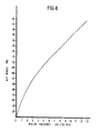
- the correct fusing conditions for a given toner are determined by a combination of roller surface temperature, pressure, nip width and paper speed. Some of the parameters are discussed by C.C. Wilson in J.P.S.E. 1979: 5:3:148-156. The choice of roller material establishes other important parameters such as offset characteristics and roller life.
- the copy sheet fixing unit preferably has means operable to adjust the roller pressure between a first relatively low value when copying and a second higher value when duplicating whereby satisfactorytoner fixing to the copy sheets can be achieved without alteration of roller temperature.
- the nip width is .10 in.
- the residence time is 2.5 millisecs. If the speed is reduced to 20 cms per second, then the residence time is 12.5 millisecs. However, if the pressure is reduced to 0.6 lbs per sq. in. then the nip width becomes .02 inch and the residence time at the slower speed of.20 cms/sec reverts to 2.5 millisecs, so that the same conditions apply as for high speed operation at a speed of 100 cms per second.
Landscapes
- Physics & Mathematics (AREA)
- General Physics & Mathematics (AREA)
- Fixing For Electrophotography (AREA)
- Combination Of More Than One Step In Electrophotography (AREA)
- Electrophotography Using Other Than Carlson'S Method (AREA)
- Control Or Security For Electrophotography (AREA)
Applications Claiming Priority (2)
| Application Number | Priority Date | Filing Date | Title |
|---|---|---|---|
| GB08139066A GB2112711A (en) | 1981-12-30 | 1981-12-30 | Improvements in or relating to electrostatographic copying and duplicating |
| GB8139066 | 1981-12-30 |
Publications (2)
| Publication Number | Publication Date |
|---|---|
| EP0083102A2 true EP0083102A2 (fr) | 1983-07-06 |
| EP0083102A3 EP0083102A3 (fr) | 1984-03-21 |
Family
ID=10526878
Family Applications (1)
| Application Number | Title | Priority Date | Filing Date |
|---|---|---|---|
| EP82112051A Withdrawn EP0083102A3 (fr) | 1981-12-30 | 1982-12-28 | Copiage et polycopiage |
Country Status (3)
| Country | Link |
|---|---|
| EP (1) | EP0083102A3 (fr) |
| JP (1) | JPS58118669A (fr) |
| GB (1) | GB2112711A (fr) |
Cited By (2)
| Publication number | Priority date | Publication date | Assignee | Title |
|---|---|---|---|---|
| EP0464804A3 (en) * | 1990-07-03 | 1992-02-12 | Oki Electric Industry Co., Ltd. | Electrophotographic process and apparatus |
| CN110605700A (zh) * | 2019-07-31 | 2019-12-24 | 重庆中烟工业有限责任公司 | 一种烟用纸张半自动取出器 |
Family Cites Families (7)
| Publication number | Priority date | Publication date | Assignee | Title |
|---|---|---|---|---|
| US2576047A (en) * | 1948-10-21 | 1951-11-20 | Battelle Development Corp | Method and apparatus for printing electrically |
| GB1139256A (en) * | 1965-08-11 | 1969-01-08 | Konishiroku Photo Ind | Electrophotographic process and device |
| CA929205A (en) * | 1967-04-21 | 1973-06-26 | Addressograph-Multigraph Corporation | Photoelectrostatic duplicator |
| US3795442A (en) * | 1968-01-26 | 1974-03-05 | T Kimura | Electroprinting device |
| US3627523A (en) * | 1968-03-14 | 1971-12-14 | Addressograph Multigraph | Multiple powder transfer in photoelectrostatic duplicator |
| US3615128A (en) * | 1968-07-11 | 1971-10-26 | Xerox Corp | Apparatus for electrostatic printing |
| JPS5473040A (en) * | 1977-11-24 | 1979-06-12 | Olympus Optical Co Ltd | Electrostatic printing method and apparatus |
-
1981
- 1981-12-30 GB GB08139066A patent/GB2112711A/en not_active Withdrawn
-
1982
- 1982-12-28 JP JP57234964A patent/JPS58118669A/ja active Pending
- 1982-12-28 EP EP82112051A patent/EP0083102A3/fr not_active Withdrawn
Cited By (2)
| Publication number | Priority date | Publication date | Assignee | Title |
|---|---|---|---|---|
| EP0464804A3 (en) * | 1990-07-03 | 1992-02-12 | Oki Electric Industry Co., Ltd. | Electrophotographic process and apparatus |
| CN110605700A (zh) * | 2019-07-31 | 2019-12-24 | 重庆中烟工业有限责任公司 | 一种烟用纸张半自动取出器 |
Also Published As
| Publication number | Publication date |
|---|---|
| EP0083102A3 (fr) | 1984-03-21 |
| GB2112711A (en) | 1983-07-27 |
| JPS58118669A (ja) | 1983-07-14 |
Similar Documents
| Publication | Publication Date | Title |
|---|---|---|
| EP0038220B1 (fr) | Machine à copier électrostatique | |
| US4035072A (en) | Programmable controller for controlling reproduction machines | |
| US4429990A (en) | Apparatus for controlling the application of fuser release material in roller fusers | |
| EP0106567B1 (fr) | Dispositif de commande d'acheminement du papier dans une machine de reproduction | |
| US3944360A (en) | Programmable controller for controlling reproduction machines | |
| EP0212781B1 (fr) | Réglage pour appareil d'avancement des feuilles | |
| US4417806A (en) | Method for effecting registration for a copying apparatus | |
| US4120034A (en) | Programmable controller for controlling reproduction machines | |
| JPH0416786B2 (fr) | ||
| JPH0314189B2 (fr) | ||
| GB1603734A (en) | Copying or printing apparatus | |
| US4104726A (en) | Programmable controller for controlling reproduction machines | |
| US4420246A (en) | Multiple reproduction apparatus | |
| EP0083102A2 (fr) | Copiage et polycopiage | |
| US4908660A (en) | Image duplicating apparatus having composite and duplex modes of operation | |
| JPS6053314B2 (ja) | 複写機 | |
| JPS60142379A (ja) | 両面画像形成装置 | |
| JPS58217976A (ja) | 記録装置 | |
| JPS6344828Y2 (fr) | ||
| JPS5820030B2 (ja) | 給紙装置における給紙ロ−ラの制御装置 | |
| JPS6118983A (ja) | 画像形成装置 | |
| JPS60142374A (ja) | 両面画像形成装置 | |
| JP2897233B2 (ja) | 原稿供給装置 | |
| JPS6330257B2 (fr) | ||
| JPS5895756A (ja) | 複写機等の制御装置 |
Legal Events
| Date | Code | Title | Description |
|---|---|---|---|
| PUAI | Public reference made under article 153(3) epc to a published international application that has entered the european phase |
Free format text: ORIGINAL CODE: 0009012 |
|
| AK | Designated contracting states |
Designated state(s): BE DE FR IT LU NL |
|
| PUAL | Search report despatched |
Free format text: ORIGINAL CODE: 0009013 |
|
| AK | Designated contracting states |
Designated state(s): BE DE FR IT LU NL |
|
| STAA | Information on the status of an ep patent application or granted ep patent |
Free format text: STATUS: THE APPLICATION IS DEEMED TO BE WITHDRAWN |
|
| 18D | Application deemed to be withdrawn |
Effective date: 19850329 |
|
| RIN1 | Information on inventor provided before grant (corrected) |
Inventor name: TYLER, RICHARD GRAHAM Inventor name: SHREEVE, NICHOLAS GILBERT Inventor name: ATKINSON, DAVID IAN HEATON Inventor name: ATKINSON, CYRIL JOHN |