EP0084514A1 - Appareil pour l'essai automatique des pneus - Google Patents
Appareil pour l'essai automatique des pneus Download PDFInfo
- Publication number
- EP0084514A1 EP0084514A1 EP83630007A EP83630007A EP0084514A1 EP 0084514 A1 EP0084514 A1 EP 0084514A1 EP 83630007 A EP83630007 A EP 83630007A EP 83630007 A EP83630007 A EP 83630007A EP 0084514 A1 EP0084514 A1 EP 0084514A1
- Authority
- EP
- European Patent Office
- Prior art keywords
- tire
- value
- testing
- sensor
- data
- Prior art date
- Legal status (The legal status is an assumption and is not a legal conclusion. Google has not performed a legal analysis and makes no representation as to the accuracy of the status listed.)
- Granted
Links
- 238000005259 measurement Methods 0.000 title description 12
- 238000012360 testing method Methods 0.000 claims abstract description 40
- 238000004519 manufacturing process Methods 0.000 claims abstract description 13
- 238000004458 analytical method Methods 0.000 claims description 24
- 238000012545 processing Methods 0.000 claims description 6
- 230000004044 response Effects 0.000 claims description 3
- 239000000523 sample Substances 0.000 description 50
- 238000000034 method Methods 0.000 description 11
- 239000004020 conductor Substances 0.000 description 6
- 238000010586 diagram Methods 0.000 description 5
- 230000007246 mechanism Effects 0.000 description 5
- 230000002950 deficient Effects 0.000 description 4
- 230000006870 function Effects 0.000 description 3
- 150000001875 compounds Chemical class 0.000 description 2
- 238000013500 data storage Methods 0.000 description 2
- 230000007547 defect Effects 0.000 description 2
- 230000000881 depressing effect Effects 0.000 description 2
- 101100522280 Dictyostelium discoideum ptpA1-2 gene Proteins 0.000 description 1
- 101150006497 PTP-1 gene Proteins 0.000 description 1
- 230000006978 adaptation Effects 0.000 description 1
- XAGFODPZIPBFFR-UHFFFAOYSA-N aluminium Chemical compound [Al] XAGFODPZIPBFFR-UHFFFAOYSA-N 0.000 description 1
- 229910052782 aluminium Inorganic materials 0.000 description 1
- 238000013459 approach Methods 0.000 description 1
- 239000011324 bead Substances 0.000 description 1
- 230000002146 bilateral effect Effects 0.000 description 1
- 238000004891 communication Methods 0.000 description 1
- 238000007405 data analysis Methods 0.000 description 1
- 238000001514 detection method Methods 0.000 description 1
- 238000006073 displacement reaction Methods 0.000 description 1
- 230000000694 effects Effects 0.000 description 1
- 239000004744 fabric Substances 0.000 description 1
- 238000012986 modification Methods 0.000 description 1
- 230000004048 modification Effects 0.000 description 1
- 238000002360 preparation method Methods 0.000 description 1
- 230000008569 process Effects 0.000 description 1
- 230000035755 proliferation Effects 0.000 description 1
- 238000003908 quality control method Methods 0.000 description 1
- 230000008672 reprogramming Effects 0.000 description 1
- 238000012216 screening Methods 0.000 description 1
Images


Classifications
-
- G—PHYSICS
- G01—MEASURING; TESTING
- G01M—TESTING STATIC OR DYNAMIC BALANCE OF MACHINES OR STRUCTURES; TESTING OF STRUCTURES OR APPARATUS, NOT OTHERWISE PROVIDED FOR
- G01M17/00—Testing of vehicles
- G01M17/007—Wheeled or endless-tracked vehicles
- G01M17/02—Tyres
-
- G—PHYSICS
- G01—MEASURING; TESTING
- G01B—MEASURING LENGTH, THICKNESS OR SIMILAR LINEAR DIMENSIONS; MEASURING ANGLES; MEASURING AREAS; MEASURING IRREGULARITIES OF SURFACES OR CONTOURS
- G01B7/00—Measuring arrangements characterised by the use of electric or magnetic techniques
- G01B7/28—Measuring arrangements characterised by the use of electric or magnetic techniques for measuring contours or curvatures
Definitions
- This invention relates to the manufacture of vehicle tires and more particularly relates to the portion of the manufacturing process which subjects the tire to a plurality of quality control tests.
- a tracking probe picks up data from a designated portion of a rotating tire, and mechanical or electrical apparatus analyzes the data according to a predetermined testing algorithm.
- the tracking probes may be arranged to obtain data from a variety of different tire surfaces.
- U.S. Patent No. 3,303,571 (Veals - February 14, 1967) describes probes arranged to track at several different locations along the sidewall and tread of the tire. Multiple tracking probes are also shown in U.S. Patent Nos. 2,251,803 (Pummill - August 5, 1941) and U. S. Patent No. 3,895,518 (Leblond - July 22, 1975).
- Prior art testing machines have been unable to cope with the proliferation of testing requirements.
- Such testing machines have one or more tracking probes which are dedicated to a specific testing algorithm. There is no convenient and reliable way to mix and match a tracking probe with more than one testing algorithm or vice versa. As a result, it is difficult, if not impossible, for prior art testing machines to readily adapt or modify the tests performed by the machine to accommodate different tolerances or performance requirements of different tire users. Rapid adaptation is essential in order to keep up with production line testing rates.
- Another object is to provide a technique of the foregoing type capable of use by production line personnel.
- Still another object is to provide a technique of the foregoing type in which test algorithms or tracking probes can be rapidly and accurately changed to accommodate different tire specifications.
- Yet another object is to provide a technique of the foregoing type in which new tracking probes or testing algorithms can be rapidly added without altering existing tracking probes or testing algorithms.
- tracking probes and testing algorithms can be mixed and matched in a rapid and reliable manner,, according to the test criteria needed to properly evaluate different .kinds of tires. Production line personnel can conveniently make the requisite modifications in order to keep up with production line rates of testing. By these techniques, the condition of a tire can be rapidly tested and with a degree of accuracy and reliability previously unobtainable.
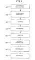
- step Ml rubber compounds are mixed and some tire fabric is coated with the compounds.
- various component parts of the tire such as tread and belts, are fabricated and cut to approximate size.
- step M2 the prepared components are assembled together on-a mandrel.
- step M3 the assembled components are cured, thereby solidifying the component parts into a unified whole.
- step M4 raw edges created during the curing process are cut or ground and, in some cases, letters and other indicia are cut into the sidewall of the tire.
- step M5 the tire is tested for defects, an important part of the overall manufacturing process.
- tires with defects, if any are indicated. Two methods of indication are: (1) marking the defective tire with an appropriate indicia, or (2) segregating defective tires from good tires.
- step M7 the tires are packaged in preparation for shipment to a customer (step M8).
- a portion of testing step M5 may be carried out by a tire force variation measuring and grinding machine suitably adapted for tracking probes which measure the lateral runout on each of the two sidewalls of a cured tire.
- a tire force variation measuring and grinding machine suitably adapted for tracking probes which measure the lateral runout on each of the two sidewalls of a cured tire.
- Such machines are well known in the art, and need not be described in detail.
- One such machine is shown in U.S. Application Serial No. 188,707, entitled “Tire Dynamic Imbalance Screening System", filed September 19, 1980 in the names of Kounkel et al., and assigned to the same assignee as the present application.
- a force variation testing machine 110 has an upper chuck 111 rotatably mounted on an upper frame 112.
- a lower frame 113 supports a vertical spindle 114 for rotation and vertical movement in a sleeve 115 attached to the frame.
- a lower chuck 116 is mounted on spindle 114 and is axially movable from an open retracted position shown in Figure 2 to a closed extended position shown in Figure 3.
- Tracking probes 118a and 118b capable of generating an analog signal proportional to the lateral runout of the tire sidewalls preferably include a tip 117a and a tip 117b.
- the probes are connected to linear displacement transducers mounted on upper frame 112 and lower frame l13 for engagement with a tire 119 mounted between chucks 111 and 116 as shown in Figure 3.
- Probes 118a and 118b are carried by measuring mechanism supports 120a and 120b, respectively, which are vertically adjustable relative to upper frame 112 and lower frame 113 to provide clearance for movement of tire 119 between upper chuck 111 and lower chuck 116.
- the vertical adjustment may be provided by air-actuated piston and cylinder apparatus mounted on frames 112 and 113 which carry the measuring mechanism supports 120a and 120b from retracted positions shown in Figure 2 to extended positions, shown in Figure 3, with tips 117a and 117b in contact with tire 119.
- Tire inflating apparatus such as a port (not shown) in one of chucks 111 or l16 is also provided for communication between the space enclosed by tire 119 and a source of air pressure.
- a load roller 123 is movable radially of tire 119 into engagement with the tread of the tire and may be used to seat the tire on the bead seats of upper chuck 111 and lower chuck 116.
- proximity sensors 124a and 124b may be carried on the measuring mechanism supports 120a and 120b for vertical adjustment into positions spaced from the tire. Sensors 124a and 124b provide signals indicating lateral runout as tire 119 is rotated on chucks 111 and 116.
- Probe 118a is shown in more detail.
- Probe 118b is identical to probe 118a and may be understood with reference to Figure 5.
- Probe 118a comprises an aluminum arm 126 bearing a carbide tip 117a.
- the arm rotates with an axle or pin 128 and is biased by a spring (not shown) which urges the arm toward the tire sidewall.
- the arm is made as light as possible and the spring force is the minimum needed to cause the tip to follow the undulations in the sidewall of the tire.
- Rotation of arm 126 caused by contact with tire 119 causes pin 128 to rotate inside a resolver 130.
- the resolver acts as a transducer which converts the movement of the probe against the sidewall of the rotating tire into a corresponding analog signal on output conductor 134 ( Figure 6).
- the signal has a value proportional to the lateral runout of the tire sidewall.
- a similar signal for the opposite sidewall is produced"on a conductor 136 connected to the transducer associated with probe 118b ( Figure 6). Additional details of resolver 130 are described in U.S. application Serial No. 270,087 entitled “Method and Apparatus For Tire Sidewall Bulge And Valley Detection", filed June 3, 1981 in the name of Jean Engel and assigned to the same assignee as the present application.
- Tire 119 is typically carried to machine 110 by an automatic conveyor and is automatically positioned upon lower chuck 116, inflated, and caused to rotate by contact with rotating roller 123.
- a pulse generator 125 ( Figure 6) attached to spindle 114 generates an electrical pulse each time the tire rotates through one degree of arc (360 pulses per revolution) and transmits the pulse over a conductor 127.
- Probes 118a and 118b are then brought into contacting engagement with opposite sidewalls Wl and W2 of the tire. As shown in Figure 5, the probes track a relatively thin section of the sidewalls about a circumference which is unobstructed by lettering or other molded depressions or protusions such that the movement of the probes are characteristic of deflections of the sidewalls themselves.
- probes 118a and 118b ride on the sidewalls of the tire, and the transducers associated with the probes produce analog signals having values proportional to the lateral runout of the sidewalls.
- the probes are able to detect a bulge B or a valley V ( Figure 4).
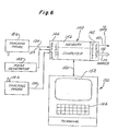
- tracking probes 118a and 118b are connected to a computer or processing device 140.
- the computer comprises a model HP 1,000 L-series manufactured by Hewlett-Packard Corporation.
- This computer has a random access memory 142, an analog input card 144 which contains an analog-to-digital converter, and a digital output card 145 which provides signals to gating and marking devices shown in Figure 9.
- the tracking probes are connected through conductors 134 and 136 to the analog input card of the computer.
- the computer also contains a terminal 150 which is preferably a model HP 2645a also manufactured by Hewlett- Packard Corporation.
- the terminal contains a CRT display 152 and a keyboard 154.
- the terminal is connected to computer 140 through a conventional buss 156 supplied by Hewlett-Packard.
- tire 110 is carried to testing machine 110 by a conventional conveyor 160. If the tire is defective, it is conveyed to a conveyor 162; if the tire is acceptable, it is conveyed to a conveyor 164. Proper conveying of the tire is achieved through a gating mechanism 166 comprising a conveyor 168 which is rotated around an axis 170 by a pneumatic controller 172. Controller 172 includes a cylinder 174 fitted with a piston 176 which raises or lowers a connecting rod 178. Compressed air is admitted to the upper or lower sides of the piston by a valve 180 controlled by a logical.gating signal transmitted over a conductor 182.
- the tire can be marked with ink by means of a marking mechanism 184 comprising 8 stamping plates 186 which are primed by an ink supply 188.
- Eight solenoids 190 (one for each plate) are capable of depressing individual plates into contact with the tire. By energizing combinations of solenoids, 2 8 different patterns of marks can be placed on the tire.
- the solenoids are controlled by an 8-bit buss 192 connected to computer 140 ( Figure 6).
- keyboard utility which requests information on CRT display 152 and enables the information to be entered through keyboard 154.
- the keyboard utility (KBU) facility is activated by depressing the space bar on keyboard 154 and then entering the code "RU, KBU (RETURN)."
- the primary menu shown in the following Table 1 will then be listed on display 152:
- Line 1 of the KBU display defines the size of one of the parameters used in the algorithm shown in Figure 7D. This parameter will be explained later in connection with Figure 7D.
- Line 2 of the KBU display enables the operator to determine the type of measurement specifications to be measured, and line 3 of the KBU ' display enables the operator to place measurement limits on those specifications. It is important that the last function entered is a zero (0) so that another activity of the apparatus can be entered.
- a variable MAX indicating the maximum number of allowable lines in Table 2 is established by the programmer.
- the value for MAX is stored in a common data storage table which is accessed by the program.
- the type numbers displayed in Table 2 identify types of analysis which can be carried out by the program.
- the program can carry out either a peak-to-peak analysis or a so-called bulge analysis.
- the programmer has assigned type number 1 to the peak-to-peak analysis and type number 2 to the bulge analysis.
- the sensor numbers displayed in Table 2 identify the sensors shown in Figure 3.
- the sensor number is assigned by determining the channel of analog input 144 into which the tracking probes are connected.
- sensor 118a is assigned number 1
- sensor 118b is assigned number 2.
- the operator can define the measurement functions of the apparatus without any reprogramming.
- Table 2 provides the ability to mix and match types of test algorithms or data analysis with different sensors. For example, the operator can choose a peak-to-peak analysis in connection with the data obtained from sensor 118a or sensor 118b. Likewise, the operator can choose a bulge analysis from sensor 118a or 118b. For each combination of analysis and sensor, the operator enters the data called for at the bottom of the Table 2 display. For example, assuming the operator wants a peak-to-peak analysis from sensor 118a, he would enter line number 1, and then type an arbitrary 4 character label (e.g., PTP1).
- PTP1 arbitrary 4 character label
- the information entered by the operator would not only be displayed on display 152, but also would be stored in memory 140 in a measurement table MESPC.
- the operator can enter limits for each of the selected analyses beyond which the tire will be judged defective, and can enter the value of an 8 bit marking code in line 4.
- Table 3 The values entered in Table 3 will not only be displayed but also stored in memory 140 for use by the analysis procedures shown in Figures 7C and 7 D .
- the apparatus is enabled to analyze tire 119.
- step S20 the program enters step S20 in which the apparatus waits for a loaded tire.
- a tire such as tire 119
- the apparatus waits for a loaded tire.
- a tire such as tire 119
- the tire is carried to the apparatus along a conveyor 160.
- the tire is automatically fitted onto chucks 111 and 116.
- the chucks are then driven to the closed position shown in Figure 3.
- a load roller 123 is then rotated and driven into contact with the tread of tire 119 so that the tire is properly aligned with the chucks and is inflated.
- pulses are sent to computer 140 from a pulse generator 125 ( Figure 6).
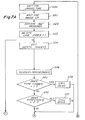
- the program enters step S21 ( Figure 7A) and waits until a predetermined time has passed, after which the program assumes that the tire is rotating at the proper speed.
- step S22 the computer samples and stores in digital form 360 values from sidewall Wl and 360 values from sidewall W2 ( Figure 3).
- One value for each of sidewall Wl and W2 is stored for each degree of rotation of tire 119.
- 360 values correspond to the entire 360 degree arc of sidewall Wl
- a like number of values correspond to the entire 360 degree arc of sidewall W2.
- the values for each degree of tire rotation are stored in a memory array IVAL in the form shown in Table 4:
- Exemplary data obtained from the first 41 samples of sensor 118a are shown in Table 4. Similar data is obtained and stored for sensor 118b, but has not been shown.
- step S23 sets a line index for the stored measurement table (MESPC) equal to 1.
- MESPC stored measurement table
- This enables the program to access the data shown in line 1 of Table 2 as indicated by step S24.
- step S26 a variable SENSOR is set equal to the sensor identified at line 1 in Table 2 (i.e, sensor 1 corresponding to sensor 118a). Since the analysis type in line 1 of Table 2 equals type 1, the program calls an analysis routine PEAK which performs a peak to peak analysis (steps S27, S28).
- step S39 the variable SAMPLE is set equal to 1.
- step S40 a variable LOWPK is set equal to the value, IVAL (1, SENSOR), of the input data shown in Table 4 for sample (degree) 1 and sensor 1 (i.e., 0).
- step S41 another variable HIGHPK is set equal to the same value.
- step S42 SAMPLE is set equal to 2.
- step S43 the value of IVAL at SAMPLE 2 and sensor 1 is compared to the value of HIGHPK. If IVAL is greater than HIGHPK, HIGHPK is set equal to IVAL at SAMPLE 2 and sensor 1 in step S44.
- step S45 the current value of IVAL is compared to the value of LOWPK. If IVAL is less than LOWPK, the current value of IVAL replaces the value of LOWPK in step S46.
- step S49 the variable VALUE is set equal to the absolute difference between HIGHPK and LOWPK. As a result, VALUE equals the peak-to-peak value of the data from sensor 1. In the example shown in Figure 8, this difference is 28 (i.e. +20 - (-8)).
- Step S50 returns the program to step S72 ( Figure 7A) in which VALUE at the current index is stored in a memory table MBUF in the manner shown in Table 5:
- step S73 if the index is less than the MAX value stored in the common data storage table, the value of the variable INDEX is increased by 1 in step S74 and the program returns to step S24 ( Figure 7A).
- the information from index line 2 in Table 2 is then accessed in steps S24 and S25, and the sensor value is changed to 2 in step S26. Since line 2 of Table 2 indicates a type 1 measurement algorithm, the PEAK routine is again called in step S28.
- the PEAK routine shown in Figure 7C is then repeated for the sensor -2 values (not shown) which are stored in a manner similar to Table 4 in memory.
- the value for the line 2 index is stored in the MBUF table as shown in Table 5. Assuming that the data from sensor 2 is the same as the data for sensor 1, the value stored in Table 5 would again be 28. In general however, the value for sensor 2 can be expected to be different from the value for sensor 1.
- steps S73 and S74 Figure 7B
- the value of INDEX is again increased by 1 to the value 3.
- the program then loops back to steps S24 and S25 in which the information from line 3 of table 2 is accessed.
- step S26 the value of sensor is changed to 1 in accordance with line 3 of Table 2.
- steps S27, S70 and S71 the BULG algorithm is called since a type 2 analysis is indicated in line 3 of Table 2.
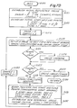
- the BULG routine begins at Step S120.
- step S121 the program establishes an initial reference base by summing values of IVAL stored in memory for sidewall Wl from the value 1 through the value of a variable IWIDE.
- IWIDE preferably equals 31, and this is the value entered in .line 1 of Table 1.
- IVAL first 31 lateral runout sample values stored in Table 4 (IVAL) are summed by the computer and stored as variable IWSUM.
- IWSUM for the first 31 degrees of rotation equals 140.
- step S122 other initial values used in connection with the first group of lateral runout values are established. That is, computer variables ISTRT, ICENTR and IFINI are established. As shown in Figure 8, these values for the first group of 31 lateral runout values equal 1, 16 and 13, ' respectively.
- step S123 program variable VALUE, corresponding to the initial sidewall bulge deformation, is set equal to 0, and SAMPLE again is set equal to 1.
- Reference values for 360 different groups of lateral runout values are ultimately calculated, and SAMPLE is established as a software counter to keep track of how many groups have been calculated. The counter is initially set equal to 1.
- step S124 the reference value IWSUM is compared to the lateral runout value at degree 16 (i.e., value ICNTR) multiplied times IWIDE.
- the result is a group deformation value (NEWVAL) indicative of the degree of deformation corresponding to the lateral runout values represented by the first 31 degrees of rotation.
- the first NEWVAL value (NEWVAL l ) is 108.
- NEWVAL is then compared with the initial VALUE in order to determine whether a new bulge value should be stored. According to step S125, a new bulge value is indicated if the current value of NEWVAL exceeds the current value of VALUE. If so, the new value is stored as a new VALUE in step S126. Since 108 (NEWVAL 1 ) is greater than 0 (VALUE), the value of VALUE is changed to 108.
- step S127 the program determines whether the variable SAMPLE equals 360. Since only one group of lateral runout values has been considered at this point in time, the answer is no, and the program moves on to step S128.
- Steps S128-S132 are used to calculate a new group value corresponding to the lateral runout values representing degrees 2-32 of sidewall rotation.
- This portion of the program can be analogized to a 31 degree-wide window which is placed over the tire in order to analyze lateral runout values which show through the window. The window is then rotated 1 degree so that one of the former values is covered up and a new value is exposed. By subtracting the covered up value and adding the newly exposed value, the sum of the values for the new group can be quickly determined without performing the complete summation required in step S121.
- the first point of the old reference group i.e., IVAL corresponding to rotation sample 1 is stored so that it can be later subtracted from the total group value.
- step S131 pointers for the same values calculated in step S122 are indexed by 1 by means of a modulus operator MOD.
- MOD This is a standard FORTRAN function which subtracts 360 before indexing in the event the variable exceeds 360. This is needed so that the proper values will be calculated when the window wraps around the entire circumference of the tire and uses some of the initial starting values in the group corresponding to degrees 1-31.
- step S132 a new reference value is calculated by subtracting the old "covered up” value (IOVAL) and adding the "newly exposed” value (i.e., IVAL at degree 32) and storing the resulting value as variable IWSUM.
- IWSUM 2 for the second group degrees 2-32 is still 34.
- the program indexes variable SAMPLE in step S133.
- the program then returns to step S124 in.order to calculate a new group value (NEWVAL) for the second group.
- N EWVAL for the second group (NEWVAL 2 ) is calculated to be 232 (see FIGURE 8). Since NEWVAL 2 is greater than the previous value for VALUE (i.e. 108), 232 is stored as the new value for VALUE in step S126.
- the program then proceeds through steps S127-S133 as previously described.
- step SAMPLE After 360 groups of values have been considered, the variable SAMPLE equals 360, and the program branches to step S129.
- step S129 VALUE is scaled by dividing by 31 (the value of IWIDE) in order to prepare the value for proper comparison with the bulge limit established in Table 3. Assuming VALUE at the beginning of step S129 was 232, VALUE at step S130 would be 232/31 or 7.48.
- step S130 the program returns to step S72 ( Figure 7B).
- step S72 the scaled VALUE value is stored in line 3 of Table 7 for later comparison to a limit.
- step S73 the program is directed on to step S150 ( Figure 7B).
- the program compares the values previously stored in Table 5 to the limits stored in Table 3.
- the line index is set equal to 1, and in step S151, the limit stored at line 1 of Table 3 (i.e., 35) is obtained. Since 35 is less than the value stored in line 1 of Table 5 (i.e., 28), the index value is increased by 1 in steps S153 and S154, and the program loops back to S151.
- the program determines whether the value stored at line 2 of Table 5 is greater than the limit stored at line 2 of Table 3.
- an output reject flag would be set in step S156 ( Figure 7B).
- the marking apparatus shown in Figure 9 can be initiated through buss 192 in order to mark the tire with indicia indicating the presence of an unacceptable bulge or peak-to-peak value.
- a logical one signal can be transmitted over conductor 182 in order- to raise conveyor gate 168 to a position adjacent conveyor 164 in order to segregate an unacceptable tire from an acceptable one.
Landscapes
- Physics & Mathematics (AREA)
- General Physics & Mathematics (AREA)
- Testing Of Balance (AREA)
- Length Measuring Devices With Unspecified Measuring Means (AREA)
Applications Claiming Priority (2)
| Application Number | Priority Date | Filing Date | Title |
|---|---|---|---|
| US06/339,876 US4434652A (en) | 1982-01-18 | 1982-01-18 | Automated tire measurement techniques |
| US339876 | 1982-01-18 |
Publications (2)
| Publication Number | Publication Date |
|---|---|
| EP0084514A1 true EP0084514A1 (fr) | 1983-07-27 |
| EP0084514B1 EP0084514B1 (fr) | 1986-08-20 |
Family
ID=23331009
Family Applications (1)
| Application Number | Title | Priority Date | Filing Date |
|---|---|---|---|
| EP83630007A Expired EP0084514B1 (fr) | 1982-01-18 | 1983-01-18 | Appareil pour l'essai automatique des pneus |
Country Status (5)
| Country | Link |
|---|---|
| US (1) | US4434652A (fr) |
| EP (1) | EP0084514B1 (fr) |
| JP (2) | JPS58129344A (fr) |
| CA (1) | CA1183606A (fr) |
| DE (1) | DE3365366D1 (fr) |
Cited By (6)
| Publication number | Priority date | Publication date | Assignee | Title |
|---|---|---|---|---|
| GB2136997A (en) * | 1983-03-22 | 1984-09-26 | Rockwell Rimoldi Spa | Processing Sample Data |
| WO1988009923A3 (fr) * | 1987-06-12 | 1988-12-29 | Eagle Picher Ind Inc | Appareil et procedes permettant d'ameliorer les mesures d'uniformite de corps rotatifs |
| EP0232213A3 (fr) * | 1986-01-27 | 1989-11-02 | The Goodyear Tire & Rubber Company | Méthode pour surveiller, sélectionner, évaluer ou entretenir les pneus de véhicules |
| EP0590436A3 (fr) * | 1992-09-28 | 1994-04-20 | Goodyear Tire & Rubber | |
| US6826951B1 (en) | 1998-01-15 | 2004-12-07 | International Marketing, Inc. | Tire management system and method for surveying and servicing a vehicle tire |
| CN111873722A (zh) * | 2020-07-30 | 2020-11-03 | 深圳市元征科技股份有限公司 | 一种胎压传感器地址写入方法及其相关装置 |
Families Citing this family (19)
| Publication number | Priority date | Publication date | Assignee | Title |
|---|---|---|---|---|
| US4440018A (en) * | 1982-01-18 | 1984-04-03 | The Goodyear Tire & Rubber Company | Tire sidewall deformation detection techniques |
| US4783992A (en) * | 1987-06-26 | 1988-11-15 | Bridgestone Corporation | Method of detecting configuration of tire |
| US5777219A (en) * | 1996-10-16 | 1998-07-07 | Bridgestone/Firestone, Inc. | Apparatus and related methods for automatically testing and analyzing tires utilizing a test pod with a slidably movable cover plate and a gray scale normalization technique |
| US6466878B1 (en) | 1996-12-27 | 2002-10-15 | The Goodyear Tire & Rubber Company | Method for selecting a tire set from a group of experimental tires |
| US5992227A (en) * | 1997-01-24 | 1999-11-30 | Jellison; Frank R. | Automatic adjustable width chuck apparatus for tire testing systems |
| US6067848A (en) * | 1997-03-07 | 2000-05-30 | Bridgestone/Firestone, Inc. | Portable tire uniformity measurement system and method |
| US5876501A (en) * | 1997-05-23 | 1999-03-02 | Fori Automation, Inc. | Wheel soaping apparatus |
| DE69718217T2 (de) * | 1997-10-08 | 2003-09-04 | The Goodyear Tire & Rubber Co., Akron | Verfahren zur anzeige charakteristischer parameter in einer zelle zur reifenherstellung |
| US6415197B1 (en) | 1997-10-08 | 2002-07-02 | The Goodyear Tire & Rubber Company | Method of displaying characteristic parameters in a tire manufacturing cell |
| US6609041B1 (en) | 1999-05-05 | 2003-08-19 | Johnson & Johnson Vision Care, Inc. | Method and system for SKU tracking and changeover |
| US6741957B1 (en) | 2000-07-21 | 2004-05-25 | Daimlerchrysler Corporation | Analytical tire model for vehicle durability and ride comfort analysis |
| JP2006234533A (ja) * | 2005-02-24 | 2006-09-07 | Honda Motor Co Ltd | 車両品質分析システム並びにプログラムファイルの管理方法およびそのプログラム |
| US7370432B2 (en) * | 2005-09-08 | 2008-05-13 | Dubois R Clark | Tape measure with detachable tape |
| EP1952998B1 (fr) | 2007-02-01 | 2011-04-06 | FUJIFILM Corporation | Appareil d'enregistrement à jet d'encre |
| DE602008006279D1 (de) | 2007-02-07 | 2011-06-01 | Fujifilm Corp | Tintenstrahlaufzeichnungsvorrichtung mit Wartungsvorrichtung für Tintenstrahldruckkopf und Wartungsverfahren für einen Tintenstrahldruckkopf |
| JP5265165B2 (ja) | 2007-09-28 | 2013-08-14 | 富士フイルム株式会社 | 塗布装置及びこれを用いるインクジェット記録装置 |
| US8011235B2 (en) * | 2009-04-16 | 2011-09-06 | Bridgestone Americas Tire Operations, Llc | Apparatus and method for measuring local tire stiffness |
| JP6234718B2 (ja) * | 2013-07-02 | 2017-11-22 | 株式会社神戸製鋼所 | タイヤ試験機 |
| JP6692181B2 (ja) * | 2016-02-29 | 2020-05-13 | 国際計測器株式会社 | 動釣合い試験装置 |
Citations (9)
| Publication number | Priority date | Publication date | Assignee | Title |
|---|---|---|---|---|
| US3725163A (en) * | 1967-02-01 | 1973-04-03 | Gen Tire & Rubber Co | Method of improving performance characteristics of pneumatic tires |
| US3740710A (en) * | 1971-06-01 | 1973-06-19 | Itt | Tire tread depth measurement system |
| US3895518A (en) * | 1973-02-19 | 1975-07-22 | Uniroyal France | Tire Testing Machine |
| US4004693A (en) * | 1974-05-09 | 1977-01-25 | Bridgestone Tire Company Limited | Apparatus for inspecting the disposition of steel ply cords in pneumatic tires |
| US4018087A (en) * | 1975-08-14 | 1977-04-19 | Gebr. Hofmann Kg | Method and apparatus for testing the uniformity of a rotary body |
| DE2907906A1 (de) * | 1978-03-14 | 1979-09-27 | Graham | Vorrichtung zur bestimmung der federkonstante eines autoreifens |
| DE2913280B2 (de) * | 1978-04-03 | 1981-07-09 | Bridgestone Tire Co. Ltd., Tokyo | Verfahren zum Korrigieren der Montage eines luftbereiften Rades |
| GB2072346A (en) * | 1980-03-03 | 1981-09-30 | Bridgestone Tire Co Ltd | Method and apparatus for inspecting a pneumatic tyre |
| US4311044A (en) * | 1980-02-25 | 1982-01-19 | The B. F. Goodrich Company | Tire sidewall bump/depression detection system |
Family Cites Families (10)
| Publication number | Priority date | Publication date | Assignee | Title |
|---|---|---|---|---|
| US2251803A (en) | 1937-12-09 | 1941-08-05 | Edwin W Pummill | Tire tester |
| US3303571A (en) | 1964-06-22 | 1967-02-14 | William E Veals | Apparatus for testing wheel mounted inflated tires |
| US3595068A (en) | 1968-06-26 | 1971-07-27 | Frank O Skidmore | Method and apparatus for balancing pneumatic tire and support |
| US3719813A (en) | 1968-09-05 | 1973-03-06 | Uniroyal Inc | Apparatus for measuring uniformity of tires |
| JPS5097411A (fr) | 1973-12-28 | 1975-08-02 | ||
| US3918816A (en) | 1974-04-22 | 1975-11-11 | Autech Corp | Tire inspection apparatus |
| US4241300A (en) | 1977-03-24 | 1980-12-23 | Eagle-Picher Industries, Inc. | Circuit responsive to rate change in amplitude of analog electrical signal for use in tire processing apparatus |
| JPS6019042B2 (ja) * | 1978-09-18 | 1985-05-14 | 株式会社東芝 | テ−プレコ−ダの録音バイアス回路 |
| US4258567A (en) | 1979-09-27 | 1981-03-31 | The Firestone Tire & Rubber Company | Tire sidewall deformity tester and method |
| US4285240A (en) | 1980-01-11 | 1981-08-25 | Fmc Corporation | Wheel unbalance measurement system and method |
-
1982
- 1982-01-18 US US06/339,876 patent/US4434652A/en not_active Expired - Lifetime
-
1983
- 1983-01-17 CA CA000419588A patent/CA1183606A/fr not_active Expired
- 1983-01-18 JP JP58005383A patent/JPS58129344A/ja active Granted
- 1983-01-18 EP EP83630007A patent/EP0084514B1/fr not_active Expired
- 1983-01-18 DE DE8383630007T patent/DE3365366D1/de not_active Expired
-
1990
- 1990-12-19 JP JP2411673A patent/JPH0629831B2/ja not_active Expired - Lifetime
Patent Citations (9)
| Publication number | Priority date | Publication date | Assignee | Title |
|---|---|---|---|---|
| US3725163A (en) * | 1967-02-01 | 1973-04-03 | Gen Tire & Rubber Co | Method of improving performance characteristics of pneumatic tires |
| US3740710A (en) * | 1971-06-01 | 1973-06-19 | Itt | Tire tread depth measurement system |
| US3895518A (en) * | 1973-02-19 | 1975-07-22 | Uniroyal France | Tire Testing Machine |
| US4004693A (en) * | 1974-05-09 | 1977-01-25 | Bridgestone Tire Company Limited | Apparatus for inspecting the disposition of steel ply cords in pneumatic tires |
| US4018087A (en) * | 1975-08-14 | 1977-04-19 | Gebr. Hofmann Kg | Method and apparatus for testing the uniformity of a rotary body |
| DE2907906A1 (de) * | 1978-03-14 | 1979-09-27 | Graham | Vorrichtung zur bestimmung der federkonstante eines autoreifens |
| DE2913280B2 (de) * | 1978-04-03 | 1981-07-09 | Bridgestone Tire Co. Ltd., Tokyo | Verfahren zum Korrigieren der Montage eines luftbereiften Rades |
| US4311044A (en) * | 1980-02-25 | 1982-01-19 | The B. F. Goodrich Company | Tire sidewall bump/depression detection system |
| GB2072346A (en) * | 1980-03-03 | 1981-09-30 | Bridgestone Tire Co Ltd | Method and apparatus for inspecting a pneumatic tyre |
Cited By (8)
| Publication number | Priority date | Publication date | Assignee | Title |
|---|---|---|---|---|
| GB2136997A (en) * | 1983-03-22 | 1984-09-26 | Rockwell Rimoldi Spa | Processing Sample Data |
| EP0232213A3 (fr) * | 1986-01-27 | 1989-11-02 | The Goodyear Tire & Rubber Company | Méthode pour surveiller, sélectionner, évaluer ou entretenir les pneus de véhicules |
| WO1988009923A3 (fr) * | 1987-06-12 | 1988-12-29 | Eagle Picher Ind Inc | Appareil et procedes permettant d'ameliorer les mesures d'uniformite de corps rotatifs |
| EP0590436A3 (fr) * | 1992-09-28 | 1994-04-20 | Goodyear Tire & Rubber | |
| TR26873A (tr) * | 1992-09-28 | 1994-08-22 | Goodyear Tire & Rubber | Pnömatik lastiklerde kat hatalarinin bulgulanmasi icin yöntem ve tertibat. |
| AU661924B2 (en) * | 1992-09-28 | 1995-08-10 | Goodyear Tire And Rubber Company, The | Method and apparatus for detecting ply defects in pneumatic tires |
| US6826951B1 (en) | 1998-01-15 | 2004-12-07 | International Marketing, Inc. | Tire management system and method for surveying and servicing a vehicle tire |
| CN111873722A (zh) * | 2020-07-30 | 2020-11-03 | 深圳市元征科技股份有限公司 | 一种胎压传感器地址写入方法及其相关装置 |
Also Published As
| Publication number | Publication date |
|---|---|
| JPH05223701A (ja) | 1993-08-31 |
| JPH0629831B2 (ja) | 1994-04-20 |
| JPS58129344A (ja) | 1983-08-02 |
| US4434652A (en) | 1984-03-06 |
| DE3365366D1 (en) | 1986-09-25 |
| CA1183606A (fr) | 1985-03-05 |
| JPH0345334B2 (fr) | 1991-07-10 |
| EP0084514B1 (fr) | 1986-08-20 |
Similar Documents
| Publication | Publication Date | Title |
|---|---|---|
| US4434652A (en) | Automated tire measurement techniques | |
| US4440018A (en) | Tire sidewall deformation detection techniques | |
| US6523408B1 (en) | Wheel balancer system with improved matching capabilities | |
| US8701479B2 (en) | System for characterizing tire uniformity machines and methods of using the characterizations | |
| US4872269A (en) | Automatic cylinder profiling gage | |
| EP0547365A2 (fr) | Procédé et dispositif pour mesurer des caractéristiques d'un pneu | |
| US4311044A (en) | Tire sidewall bump/depression detection system | |
| CN112345273A (zh) | 一种轮胎高速均匀性设备控制胎监测方法 | |
| US8943881B2 (en) | System for characterizing tire uniformity machines and methods of using the characterizations | |
| EP1624294B1 (fr) | Vérification de l'uniformité de pneus | |
| CA2015171C (fr) | Methode et dispositif de fabrication de pneu a masse plus uniforme | |
| US9140628B2 (en) | System for characterizing tire uniformity machines and methods of using the characterizations | |
| EP2827121B1 (fr) | Système de caractérisation de machines d'uniformité de pneu et leurs procédés d'utilisation des caractérisations | |
| EP2827120A1 (fr) | Système de caractérisation de machines d'uniformité de pneu et leurs procédés d'utilisation des caractérisations | |
| US4783992A (en) | Method of detecting configuration of tire | |
| WO1992001918A1 (fr) | Procede et appareil destines a apparier des pneus et des roues | |
| CA1206555A (fr) | Technique de detection de la deformation des flancs de pneus | |
| CN115752856B (zh) | 一种轮胎接地压力检测方法、系统以及车辆 | |
| US20040163455A1 (en) | Tire testing machine and process | |
| US5167094A (en) | Method of correcting lateral force variations in a pneumatic tire | |
| EP1429134B1 (fr) | Procede et dispositif pour tester l'uniformité des pneus | |
| JPH01176911A (ja) | ユニフオミテイーマシンに於けるタイヤ外径測定方法及びその装置 | |
| EP1019692B1 (fr) | Procedes de chauffage adaptatif d'une machine de test de variations de force | |
| KR0166408B1 (ko) | 타이어 비이드내경측정장치 | |
| KR0171454B1 (ko) | 타이어의 균일성시험방법 |
Legal Events
| Date | Code | Title | Description |
|---|---|---|---|
| PUAI | Public reference made under article 153(3) epc to a published international application that has entered the european phase |
Free format text: ORIGINAL CODE: 0009012 |
|
| AK | Designated contracting states |
Designated state(s): DE FR GB |
|
| 17P | Request for examination filed |
Effective date: 19830127 |
|
| GRAA | (expected) grant |
Free format text: ORIGINAL CODE: 0009210 |
|
| AK | Designated contracting states |
Kind code of ref document: B1 Designated state(s): DE FR GB |
|
| REF | Corresponds to: |
Ref document number: 3365366 Country of ref document: DE Date of ref document: 19860925 |
|
| ET | Fr: translation filed | ||
| PLBI | Opposition filed |
Free format text: ORIGINAL CODE: 0009260 |
|
| 26 | Opposition filed |
Opponent name: SEICHTER GMBH Effective date: 19870519 |
|
| REG | Reference to a national code |
Ref country code: FR Ref legal event code: CL |
|
| PGFP | Annual fee paid to national office [announced via postgrant information from national office to epo] |
Ref country code: GB Payment date: 19921216 Year of fee payment: 11 Ref country code: FR Payment date: 19921216 Year of fee payment: 11 |
|
| PGFP | Annual fee paid to national office [announced via postgrant information from national office to epo] |
Ref country code: DE Payment date: 19930127 Year of fee payment: 11 |
|
| RDAG | Patent revoked |
Free format text: ORIGINAL CODE: 0009271 |
|
| STAA | Information on the status of an ep patent application or granted ep patent |
Free format text: STATUS: PATENT REVOKED |
|
| 27W | Patent revoked |
Effective date: 19920922 |
|
| GBPR | Gb: patent revoked under art. 102 of the ep convention designating the uk as contracting state |
Free format text: 920922 |
|
| APAH | Appeal reference modified |
Free format text: ORIGINAL CODE: EPIDOSCREFNO |