EP0088445A1 - Circuit pour transmettre de l'énergie en direction et en provenance de bobines - Google Patents
Circuit pour transmettre de l'énergie en direction et en provenance de bobines Download PDFInfo
- Publication number
- EP0088445A1 EP0088445A1 EP83102313A EP83102313A EP0088445A1 EP 0088445 A1 EP0088445 A1 EP 0088445A1 EP 83102313 A EP83102313 A EP 83102313A EP 83102313 A EP83102313 A EP 83102313A EP 0088445 A1 EP0088445 A1 EP 0088445A1
- Authority
- EP
- European Patent Office
- Prior art keywords
- circuit
- coil
- energy
- switch
- transmitting
- Prior art date
- Legal status (The legal status is an assumption and is not a legal conclusion. Google has not performed a legal analysis and makes no representation as to the accuracy of the status listed.)
- Granted
Links
Images




Classifications
-
- H—ELECTRICITY
- H01—ELECTRIC ELEMENTS
- H01F—MAGNETS; INDUCTANCES; TRANSFORMERS; SELECTION OF MATERIALS FOR THEIR MAGNETIC PROPERTIES
- H01F7/00—Magnets
- H01F7/06—Electromagnets; Actuators including electromagnets
- H01F7/08—Electromagnets; Actuators including electromagnets with armatures
- H01F7/18—Circuit arrangements for obtaining desired operating characteristics, e.g. for slow operation, for sequential energisation of windings, for high-speed energisation of windings
-
- H—ELECTRICITY
- H01—ELECTRIC ELEMENTS
- H01F—MAGNETS; INDUCTANCES; TRANSFORMERS; SELECTION OF MATERIALS FOR THEIR MAGNETIC PROPERTIES
- H01F6/00—Superconducting magnets; Superconducting coils
- H01F6/006—Supplying energising or de-energising current; Flux pumps
-
- Y—GENERAL TAGGING OF NEW TECHNOLOGICAL DEVELOPMENTS; GENERAL TAGGING OF CROSS-SECTIONAL TECHNOLOGIES SPANNING OVER SEVERAL SECTIONS OF THE IPC; TECHNICAL SUBJECTS COVERED BY FORMER USPC CROSS-REFERENCE ART COLLECTIONS [XRACs] AND DIGESTS
- Y10—TECHNICAL SUBJECTS COVERED BY FORMER USPC
- Y10S—TECHNICAL SUBJECTS COVERED BY FORMER USPC CROSS-REFERENCE ART COLLECTIONS [XRACs] AND DIGESTS
- Y10S505/00—Superconductor technology: apparatus, material, process
- Y10S505/825—Apparatus per se, device per se, or process of making or operating same
- Y10S505/867—Electric power conversion system
- Y10S505/868—Current conversion
Definitions
- This invention relates to circuit arrangements for transmitting energy to and from coils, or for transmitting the energy stored in a coil to another coil through a capacitor.
- Fig. 1 illustrates a circuit arrangement of this type, as disclosed in copending European application No. Vietnamese application No. Vietnamese application No......... of even date the disclosure of which is hereby incorporated by reference.
- a circuit comprising a capacitor 1 used in single polarity, diodes 21, 22, a coil 31 for releasing energy, a coil 41 for absorbing energy, self-controllable on-off switches 51, 52, a circuit 81 for controlling the flow rate (current flow time/duty ratio) of the current to control the on-off operation of the switch 51 so as to make the voltage of the capacitor 1 constant, and a circuit 82 for controlling the flow time of the current by turning on and off the switch 52.
- a circuit comprising a capacitor 1 used in single polarity, diodes 21, 22, a coil 31 for releasing energy, a coil 41 for absorbing energy, self-controllable on-off switches 51, 52, a circuit 81 for controlling the flow rate (current flow time/duty ratio) of the current to control the on-off operation of the switch 51
- Figs. 2(a) - 2(d) show the operating modes of the switches 51, 52 and the directions of the current flowing in the circuit; making it clear that there are four kinds of operating modes.
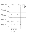
- Figs. 3(a) - (e) illustrate an example of the waveform of each component when Jt is set as a time controlling interval.
- Figs. 3(a) - (e) show the voltage Vc across the terminals of the capacitor 1, the waveform i D21 of the current drawn by the diode 21, the voltage Vl across the terminals of the coil 31, the waveform i s52 of the current drawn by the switch 52, and voltage V2 across the terminals of the coil 41, respectively.
- the switch 51 is controlled in such a way that the flow rate of the current therein is regulated by the control circuit 81 so as to make the voltage across the terminals of the capacitor 1 substantially constant and such that it is turned on and off at preset time intervals.
- the flow rate of the current directed into the switch 52 is regulated by the control circuit 82 so that it is turned on and off at preset time intervals and operates to control the voltage applied to the coil 41 according to the quantity of the energy transmitted to the coil 41.
- the circuit shown in Fig. 1 Since the circuit shown in Fig. 1 is constructed as above, it has disadvantages such that the transmission of energy between coils is unidirectional and such that, when a coil with less energy loss, such as a supercondu- tive coil or the like, is used as a load, energy must be consumed by an energy releasing circuit (not shown) each time the operation of the coil 41 is terminated; the problem is that the direction of the current flowing through the coil is unidirectional only.
- the present invention has been made in light of the above problems, and an object of the invention is to provide a circuit in which it is made possible to transmit energy to and from coils by connecting a coil to a bridge circuit comprising a diode and an on-off self-controllable switch. Another object is to provide a new circuit capable of controlling the current flowing through the coil so as to make its direction reversible.
- the circuit comprises a capacitor 1 used in single polarity, gate turn-off thyristors 11, 12 used as on-off self-controllable switches, diodes 21, 22, and a coil 30 for transmitting energy.
- the operation of the circuit in the above example will now be described.
- the operation of releasing energy from the coil 30 is conducted by simultaneously turning off the switches 11, 12, whereas that of absorbing the energy into the coil 30 is conducted by simultaneously turning on the switches 11, 12.
- the operation of maintaining the energy is carried out by alternately turning the switches 11, 12 on and off.
- the control of the quantity of the energy to be transmitted in each operation is conducted by controlling the flow ' rate of the current flowing through the switches 11, 12.
- Fig. 5 illustrates the direction of the current in a circuit employed for describing circuit operation; the currentsflowing through the switches 11, 12 are represented by I s11 , Is 12 and that flowing through the diodes 21, 22 by I D21 , I D22 .
- the current flowing toward the capacitor 1 from the circuit 201 is given by Id.
- the circuit on the lefthand side of Fig. 4 is used for description in Fig. 5, the righthand circuit of Fig. 4 is identical to the left-hand one.
- Fig. 6 shows a current route in the mode of releasing energy from the coil 30, whereas Figs. 7(a) - (f) indicate the waveform of the current in each component in Fig. 5 when the flow rate (duty ratio) of the current flowing through the switches 11, 12 is regulated to reduce it to less than 50 %.
- Figs. 8(1) and 8(2) show current routes in the mode of holding energy in the coil 30, whereas Figs. 9(a) - (f) indicate the waveforms of the current in each component when the flow rate (duty. ratio) of the current flowing through the switches 11, 12 is regulated to make it remain at 50 %.
- Fig. 10 refers to a current route in the mode of absorbing energy in the coil
- Fig. 11 shows the waveform of the current in each component when the flow rate (duty ratio) of the current flowing through the switches 11, 12 is regulated to reduce it to more than 50 %.
- the switches 11, 12 which are connected to the coil which is releasing energy are controlled by the control circuits 81 in terms of the current flow time in a manner such that the voltage across the terminals of the capacitor 1 is maintained at a constant value.
- the switches 11, 12 connected to the coil which is absorbing energy are controlled by the control circuits 81 such that the flow rate of the current is proportional to the quantity of energy to be transmitted.
- the switches 11, 12 are operated in a manner such that they are repeatedly alternately turned on and off at the flew rate (duty ratio) of 50 %.
- the circuit shown in Fig. 4 is capable of releasing, holding and absorbing energy using one type of circuit configuration.
- Fig. 12 illustrates an example of a further circuit in which the direction of the current flowing through the coil can be controlled so as to make it reversible.
- Fig. 12 illustrates an example of the energy transmitting circuit 201 described previously, and an example of a further circuit 301 capable of controlling the direction of the current flowing through the coil so as to make it reversible.
- the device of Fig. 12 employs gate turn-off thyristors 11, 12, 51, 52 employed as on-off self-controllable switches, diodes 21, 22, 61, 62, a coil 30 for transmitting energy, a control circuit 81 for controlling the on-off self-controllable switches 11, 12, 51, 52, and a switching circuit 91 for switching the control signals to be applied to the on-off self-controllable switches depending on the direction of the current flowing through the coil.
- the switches 11, 12 and diodes 21, 22 of the circuit 301 will not operate as circuit elements constituting part of the current route, but the circuit will operate in such a manner that the switches 51, 52 and diodes 61, 62 constitute the current route, whereas the switches 11, 12 are controlled so that they are left open by the switching circuit 91.
- the switches 51, 52 are turned on and off with the same current flow rate (duty ratio) controll applicable to the switches 11, 12 when the former operates to release, hold and absorb energy in the coils.
- circuit 301 in Fig. 12 operates so as to make it.possible to release, hold and absorb energy as well as to reverse the direction of the current flowing through the coil, using only one circuit configuration.
- gate turn-off thyristors have been employed as the on-off self-control- lableswitches 11, 12, chopper circuits composed of thyristors, transistors, reverse conducting thyristors and the like which are on-off self-controllable and are provided with equivalent functions may be used in place of the gate turn-off thyristors.
- Fig. 13 illustrates another example employing reverse conducting thyristors, wherein the drawing shows reverse conducting thyrstors 101, 102, 103, 104, commutation reverse conducting thyristors 111, 112, 113, 114, commutation capacitors 121, 122, 123, 124, and commutation reactors 131, 132, 133, 134; apart from these components, this circuit is constructed in the same way as the above examples.
- the transmission of energy in either direction between coils is thus made possible in the circuit for transmitting energy to and from coils according to the present invention, and, because the operating frequency of the circuit becomes twice as large as the on-off frequency of the on-off self-controllable switch, a ripple in the voltage across the terminals of the capacitor is reduced, so that the capacitance of the capacitor may be selected at a small value.
- a modified version of the present invention can control the direction of the current flowing through the coil so as to made the same reversible.
Landscapes
- Physics & Mathematics (AREA)
- Electromagnetism (AREA)
- Engineering & Computer Science (AREA)
- Power Engineering (AREA)
- Superconductor Devices And Manufacturing Methods Thereof (AREA)
- Power Conversion In General (AREA)
- Relay Circuits (AREA)
- Rectifiers (AREA)
Applications Claiming Priority (2)
| Application Number | Priority Date | Filing Date | Title |
|---|---|---|---|
| JP38914/82 | 1982-03-09 | ||
| JP57038914A JPS58154345A (ja) | 1982-03-09 | 1982-03-09 | コイル間エネルギ−転送回路 |
Publications (2)
| Publication Number | Publication Date |
|---|---|
| EP0088445A1 true EP0088445A1 (fr) | 1983-09-14 |
| EP0088445B1 EP0088445B1 (fr) | 1986-06-18 |
Family
ID=12538467
Family Applications (1)
| Application Number | Title | Priority Date | Filing Date |
|---|---|---|---|
| EP83102313A Expired EP0088445B1 (fr) | 1982-03-09 | 1983-03-09 | Circuit pour transmettre de l'énergie en direction et en provenance de bobines |
Country Status (4)
| Country | Link |
|---|---|
| US (1) | US4584518A (fr) |
| EP (1) | EP0088445B1 (fr) |
| JP (1) | JPS58154345A (fr) |
| DE (1) | DE3364136D1 (fr) |
Cited By (5)
| Publication number | Priority date | Publication date | Assignee | Title |
|---|---|---|---|---|
| FR2629942A1 (fr) * | 1988-04-08 | 1989-10-13 | Comp Generale Electricite | Dispositif d'accumulation d'energie dans une inductance supraconductrice |
| EP0455960A1 (fr) * | 1990-05-08 | 1991-11-13 | Asea Brown Boveri Ag | Convertisseur réversible et son application comme élément de régulation d'un accumulateur d'énergie |
| EP0410128A3 (en) * | 1989-07-25 | 1992-04-15 | Superconductivity, Inc. | Superconductive voltage stabilizer |
| WO1995028721A1 (fr) * | 1994-04-16 | 1995-10-26 | Robert Bosch Gmbh | Procede et dispositif de commande de consommateurs electromagnetiques |
| KR100764337B1 (ko) * | 2002-02-19 | 2007-10-05 | 가부시끼가이샤 케미컬 오토 | 디젤 배기 가스의 정화 필터 |
Families Citing this family (8)
| Publication number | Priority date | Publication date | Assignee | Title |
|---|---|---|---|---|
| DE3739411A1 (de) * | 1987-11-20 | 1989-06-01 | Heidelberg Motor Gmbh | Stromspeicher |
| JPH0693692B2 (ja) * | 1988-12-21 | 1994-11-16 | 三菱電線工業株式会社 | ループ型ローカルエリアネットワークの集線装置 |
| US5159261A (en) * | 1989-07-25 | 1992-10-27 | Superconductivity, Inc. | Superconducting energy stabilizer with charging and discharging DC-DC converters |
| US5194803A (en) * | 1989-07-25 | 1993-03-16 | Superconductivity, Inc. | Superconductive voltage stabilizer having improved current switch |
| DE4104274C2 (de) * | 1991-02-13 | 1993-10-07 | Eurosil Electronic Gmbh | Verfahren zur Regelung der Versorgungsspannung für eine Last |
| AU646957B2 (en) * | 1991-07-01 | 1994-03-10 | Superconductivity, Inc. | Shunt connected superconducting energy stabilizing system |
| US5181170A (en) * | 1991-12-26 | 1993-01-19 | Wisconsin Alumni Research Foundation | High efficiency DC/DC current source converter |
| DE19536469C1 (de) * | 1995-09-29 | 1997-04-17 | Siemens Ag | Supraleitendes torusförmiges Magnetsystem |
Family Cites Families (5)
| Publication number | Priority date | Publication date | Assignee | Title |
|---|---|---|---|---|
| SU444172A1 (ru) * | 1973-02-12 | 1974-09-25 | Предприятие П/Я В-2672 | Ключевой стабилизатор напр жени |
| US4257092A (en) * | 1977-06-03 | 1981-03-17 | Westinghouse Electric Corp. | Traction motor current control apparatus |
| US4135236A (en) * | 1977-09-15 | 1979-01-16 | Litton Industrial Products Inc. | DC-to-DC chopper circuit |
| JPS5931234B2 (ja) * | 1977-09-30 | 1984-07-31 | 株式会社日立製作所 | コイルによるエネルギ−貯蔵方式 |
| SU855893A1 (ru) * | 1979-11-06 | 1981-08-15 | Харьковский Ордена Ленина Политехнический Институт Им. В.И.Ленина | Тиристорный преобразователь посто нного напр жени дл управлени двигателем посто нного тока |
-
1982
- 1982-03-09 JP JP57038914A patent/JPS58154345A/ja active Granted
-
1983
- 1983-03-09 DE DE8383102313T patent/DE3364136D1/de not_active Expired
- 1983-03-09 EP EP83102313A patent/EP0088445B1/fr not_active Expired
- 1983-03-09 US US06/473,405 patent/US4584518A/en not_active Expired - Lifetime
Non-Patent Citations (1)
| Title |
|---|
| Patent Abstracts of Japan vol. 4, no. 189, 25 December 1980 & JP-A-55-132084 * |
Cited By (7)
| Publication number | Priority date | Publication date | Assignee | Title |
|---|---|---|---|---|
| FR2629942A1 (fr) * | 1988-04-08 | 1989-10-13 | Comp Generale Electricite | Dispositif d'accumulation d'energie dans une inductance supraconductrice |
| EP0410128A3 (en) * | 1989-07-25 | 1992-04-15 | Superconductivity, Inc. | Superconductive voltage stabilizer |
| EP0455960A1 (fr) * | 1990-05-08 | 1991-11-13 | Asea Brown Boveri Ag | Convertisseur réversible et son application comme élément de régulation d'un accumulateur d'énergie |
| US5204548A (en) * | 1990-05-08 | 1993-04-20 | Asea Brown Boveri Ltd. | Energy storage circuit with dc chopper superconducting reactor |
| WO1995028721A1 (fr) * | 1994-04-16 | 1995-10-26 | Robert Bosch Gmbh | Procede et dispositif de commande de consommateurs electromagnetiques |
| US5729422A (en) * | 1994-04-16 | 1998-03-17 | Robert Bosch Gmbh | Device and method for triggering an electromagnetic consumer |
| KR100764337B1 (ko) * | 2002-02-19 | 2007-10-05 | 가부시끼가이샤 케미컬 오토 | 디젤 배기 가스의 정화 필터 |
Also Published As
| Publication number | Publication date |
|---|---|
| US4584518A (en) | 1986-04-22 |
| EP0088445B1 (fr) | 1986-06-18 |
| DE3364136D1 (en) | 1986-07-24 |
| JPS58154345A (ja) | 1983-09-13 |
| JPS6233822B2 (fr) | 1987-07-23 |
Similar Documents
| Publication | Publication Date | Title |
|---|---|---|
| EP0602835B1 (fr) | Circuits de commande de tension | |
| EP0088445A1 (fr) | Circuit pour transmettre de l'énergie en direction et en provenance de bobines | |
| DE3786366T2 (de) | Netzabschalter mit Batteriereserve. | |
| US4777406A (en) | High voltage power supply particularly adapted for a TWT | |
| US4866344A (en) | High voltage power supply for a microwave electron tube | |
| KR20010014757A (ko) | 단일 인덕터를 갖는 다중 출력 벅 변환기 | |
| US3569817A (en) | Direct current transmitter | |
| US5293111A (en) | Method for minimizing the switching loss in a power switch | |
| DE60112627T2 (de) | Schaltnetzteil | |
| EP0079130B1 (fr) | Circuit réactif de coupure à décharge pour charges inductives munies de diodes à supprimer | |
| DE2026466A1 (de) | Elektrisches Festkörper Schaltrelais | |
| EP0088444A1 (fr) | Circuit pour transmettre de l'énergie en direction et en provenance de bobines | |
| EP0099596A1 (fr) | Circuit d'alimentation en courant électrique | |
| EP0093018A2 (fr) | Relais sans contact | |
| DE69628058T2 (de) | Schaltnetzteil | |
| SU1598073A1 (ru) | Импульсный регул тор посто нного напр жени | |
| DE3600170A1 (de) | Induktionsheizgeraet | |
| RU2035834C1 (ru) | Стабилизирующий мостовой преобразователь постоянного напряжения | |
| SU1049875A1 (ru) | Регул тор напр жени посто нного тока | |
| SU928320A1 (ru) | Стабилизирующий преобразователь переменного напр жени в посто нное | |
| KR100221455B1 (ko) | 스위칭 로스 저감 전원장치 | |
| CA1284819C (fr) | Circuit convertisseur | |
| SU1545310A1 (ru) | Полумостовой преобразователь посто нного напр жени | |
| JPH0711931B2 (ja) | 直流スイツチ | |
| SU1598078A1 (ru) | Преобразователь посто нного напр жени в посто нное |
Legal Events
| Date | Code | Title | Description |
|---|---|---|---|
| PUAI | Public reference made under article 153(3) epc to a published international application that has entered the european phase |
Free format text: ORIGINAL CODE: 0009012 |
|
| AK | Designated contracting states |
Designated state(s): DE FR GB |
|
| 17P | Request for examination filed |
Effective date: 19831020 |
|
| GRAA | (expected) grant |
Free format text: ORIGINAL CODE: 0009210 |
|
| AK | Designated contracting states |
Kind code of ref document: B1 Designated state(s): DE FR GB |
|
| REF | Corresponds to: |
Ref document number: 3364136 Country of ref document: DE Date of ref document: 19860724 |
|
| ET | Fr: translation filed | ||
| PLBI | Opposition filed |
Free format text: ORIGINAL CODE: 0009260 |
|
| 26 | Opposition filed |
Opponent name: KERNFORSCHUNGSZENTRUM KARLSRUHE GMBH Effective date: 19870312 |
|
| PLBN | Opposition rejected |
Free format text: ORIGINAL CODE: 0009273 |
|
| STAA | Information on the status of an ep patent application or granted ep patent |
Free format text: STATUS: OPPOSITION REJECTED |
|
| 27O | Opposition rejected |
Effective date: 19881229 |
|
| PGFP | Annual fee paid to national office [announced via postgrant information from national office to epo] |
Ref country code: GB Payment date: 19930301 Year of fee payment: 11 |
|
| PGFP | Annual fee paid to national office [announced via postgrant information from national office to epo] |
Ref country code: FR Payment date: 19930309 Year of fee payment: 11 |
|
| PGFP | Annual fee paid to national office [announced via postgrant information from national office to epo] |
Ref country code: DE Payment date: 19930319 Year of fee payment: 11 |
|
| PG25 | Lapsed in a contracting state [announced via postgrant information from national office to epo] |
Ref country code: GB Effective date: 19940309 |
|
| GBPC | Gb: european patent ceased through non-payment of renewal fee |
Effective date: 19940309 |
|
| PG25 | Lapsed in a contracting state [announced via postgrant information from national office to epo] |
Ref country code: FR Effective date: 19941130 |
|
| PG25 | Lapsed in a contracting state [announced via postgrant information from national office to epo] |
Ref country code: DE Effective date: 19941201 |
|
| REG | Reference to a national code |
Ref country code: FR Ref legal event code: ST |