EP0089525B1 - Druckschalter - Google Patents
Druckschalter Download PDFInfo
- Publication number
- EP0089525B1 EP0089525B1 EP83102090A EP83102090A EP0089525B1 EP 0089525 B1 EP0089525 B1 EP 0089525B1 EP 83102090 A EP83102090 A EP 83102090A EP 83102090 A EP83102090 A EP 83102090A EP 0089525 B1 EP0089525 B1 EP 0089525B1
- Authority
- EP
- European Patent Office
- Prior art keywords
- actuator
- seat
- diaphragm
- pressure
- pressure switch
- Prior art date
- Legal status (The legal status is an assumption and is not a legal conclusion. Google has not performed a legal analysis and makes no representation as to the accuracy of the status listed.)
- Expired
Links
Images

Classifications
-
- H—ELECTRICITY
- H01—ELECTRIC ELEMENTS
- H01H—ELECTRIC SWITCHES; RELAYS; SELECTORS; EMERGENCY PROTECTIVE DEVICES
- H01H35/00—Switches operated by change of a physical condition
- H01H35/24—Switches operated by change of fluid pressure, by fluid pressure waves, or by change of fluid flow
- H01H35/34—Switches operated by change of fluid pressure, by fluid pressure waves, or by change of fluid flow actuated by diaphragm
Definitions
- the invention relates to a pressure switch of the type as indicated in the preamble of the main claim.
- Pressure responsive switches are used in such systems in which an electrical circuit must be closed and opened in response to a defined pressure. It has been found that such pressure switches work more accurately if a dual compression spring concept is employed in which the trip point is determined by the combined forces of the two springs while the reset point is determined by the force of only one of the springs.
- US-A-3230328 discloses such a pressure switch in which the first spring is mounted between a seat fixedly connected to the moveable actuator and a seat fixedly but adjustable, connected to a threaded extension with an adjusting nut which is fixedly connected to the housing.
- the second spring is mounted between a slideable plate normally pressed against a ledge by the force of the second spring and being able to be picked up by the actuator at a point of its movement, and a seat fixedly but adjustable, connected to the housing.
- the construction of this pressure switch is very complicated and unfavourable with respect to the assembling procedure.
- US-A-3366760 shows a pressure switch whose springs are loosely mounted between the lower part and upper parts of the housing exclusively.
- the plate shaped actuator shows at its upper side a lower elevation and an upper elevation which are adapted to abut the springs one after another when the actuator is caused to move upwardly through a slot in the lower seat.
- the upper seats of the springs are arranged on a plunger and a piston removeably and adjustably connected to the housing.
- the mounting of this switch is still more difficult than the mounting of the above described switch because both springs must be held in position until the plunger and the piston are at their exact places.
- This switch must also have a minimum size and requires calibration under real, exactly defined pressures.
- an actuator-spring-subassembly is easy to fabricate and to handle during the subsequent assembly into the pressure switch even if the parts are very small. Because the distance between the seats and the associated limit stops may be exactly calculated with respect to the springs and with respect to the desired switching pressure prior to assembling, and the calculated values may be maintained exactly during assembling no further calibrating under real pressures is necessary.
- the design arrangement is such that the requisite large pressure differentials of the trip and reset can be obtained with low rate springs which permit fabrication with precise, accurate switching points.
- the terminal arrangement according to claim 6, greatly simplifies assembly while ensuring accurate location of the switch lead and terminals to maintain accuracy of calibration.
- a diaphragm according to claim 9 which has a consistent effective area from diaphragm to diaphragm and the diaphragm must be substantially impermeable to Freon-12° and the oil entrained in the Freon in the refrigeration system. Furthermore, the diaphragm must not exert forces of its own since such forces become a further variable in the system. Hydrin@ and Buna-N @ diaphragm materials tested were permeable to Freon and oil when made sufficiently thin to meet the other requirements of the diaphragm.
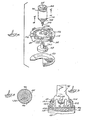
- the pressure switch housing is made up of lower 10, intermediate 12 and upper 14 plastic parts held together by the circular clamp ring 16 crimped over the shoulders of the upper and lower parts.
- the intermediate part forms a partition in the housing and serves to guide and limit motion of the diaphragm pad and to locate the terminals and switch.
- the lower housing 10 has an inlet 18 threaded for connection to the air conditioning system, usually at a point at or near the evaporator outlet.
- the Freon refrigerant in the system exerts pressure at the inlet and this pressure is transmitted to the space below diaphragm 20 through conduit 22.
- Diaphragm 20 is a thin polyimide film which is cold formed (as may be seen in dotted lines in Figure 1 and in perspective in Figure 4) to be slightly domed so that it assumes the position shown in Figure 1, and when fully extended upwardly will have substantially the same shape but extends in the other direction.
- the polyimide film circumference abuts the inside of the locating lugs 24 of the intermediate housing member.
- the intermediate housing member clamps the film in place with the O-ring 26 sealing against the film to prevent leakage from the pressure chamber underneath the diaphragm.
- the polyimide film is substantially impervious to Freon and oil entrained in the Freon.
- the cold formed shape of the film does not impose any forces which could adversely affect the trip and reset points of the pressure switch.
- the film does not stretch or wrinkle in use to any significant extent. Therefore, the area of the film is considered constant and does not introduce a variable into the calculated performance of the pressure switch.
- the diaphragm pad 28 resting on top of the diaphragm has a central boss 30 extending through and guided by the central hole 32 in the intermediate housing member.
- the boss has a central bore 34 receiving the lower end 36 of actuator 38.
- the collar 40 immediately above the lower end 36 of the actuator rests against the upper end of the boss 30.
- the actuator is provided with a groove or reduced diameter section 42 which engages the narrow portion of the key slot 44 in the actuating tongue 46 of the switch 48.
- the switch has a blade having side rails 50, 50 extending from the fixed end 52 of the switch to the contact carrying end 54.
- the contact carrying end includes a cross member 55 to which the switch contact 56 is secured.
- Barrel spring 58 is compressed between the contact carrying end 54 and the actuating tongue 46 and biases the blade up or down and drives the blade from one position to the other with a snap action as the force component of the spring goes over center.
- the contact 56 engages pad 60 molded in the upper housing part and a lower position in which it engages contact 62 fixed on the bent support portion 63 of the formed terminal 64 there is considerable freedom of movement of the switch tongue relative to the groove 42. This insures good snap action when the blade goes over center and avoids overstressing the switch.
- the head or upper end of the actuator 38 is received in and guided by the upper reduced diameter portion 90 of the guide tube or tubular recess 91 in the upper housing.
- Actuator 38 is provided with a washer 66 bearing against the underside of head 68 by reason of compression of spring 70 between the washer 66 and a lower washer 72 loosely fitted over the actuator 38 and retained in position by means of the E-type retaining ring 74 engaging groove 78 in the actuator. Both washers serve as spring seats with the lower seat 72 being, in effect, fixed.
- spring 70 In the position shown in Figure 1, spring 70 is bearing against internal shoulder or stop 80 and fixed washer 72 forcing the actuator down to the extent permitted by engagement of collar 40 with the upper end of the boss 30 of the diaphragm pad which is pressed against the lands or pads 82 in the chamber under the diaphragm. Thus, spring 70 urges the actuator 38 downwardly in Figure 1. In Figure 1 washer 66 also seats against head 68 so the force of spring 70 may be cancelled until the first small movement of the pad and actuator.
- Trip spring 84 is compressed between the fixed seat 72 and a washer/seat 86 bearing against the shoulder 88 at the upper end of the actuator.
- Seat 86 has a larger outside diameter than the inside diameter of seat 66 and will, therefore, engage seat 66 as the actuator is moved upwardly by reason of increasing pressure underneath the diaphragm.
- the reset spring 70 is compressed while the actuator pin 38 rises.
- seat 86 will engage seat 66.
- trip spring 84 is being compressed along with the reset spring 70. After an additional 1/4 stroke, the tongue of the switch will be at the point where the barrel spring goes over center and snaps the switch contact down to engage contact 62.
- the actuator can rise another 1/4 of the total stroke before the diaphragm pad 28 engages the underside of the intermediate member and prevents further upward movement of the actuator. At this time the actuator will almost contact the top of the recess or guide tube.
- the spring assembly is a complete subassembly which can be assembled outside before assembling it into the upper housing 14.
- the two springs are assembled between seat 72 and the two upper seats 66, 86 and the retaining ring is applied. Handling the subassembly will not affect the inherent calibration provided by the low rate springs which will hold their characteristics over a long life. Normally, trying to assemble comparable springs into a pressure switch is very tricky at best. But, with this arrangement the assembly time and, therefore, the cost of assembly is greatly reduced.
- the terminal mounting is simple and accurate.
- the fixed end 52 of the switch 48 is connected by rivet 96 to the support 92 bent at right angles to the terminal 94.
- the terminal includes a long connector 98 which projects through the slot 100 in the upper housing 14 to extend beyond the body.
- the terminal shoulders 102 engage the flat surface 104 inside the upper housing 14.
- the shoulders 102 are held between the flat surface 104 and the ribs 106 on member 12 to retain the terminal in a precise location.
- Terminal 64 is similarly mounted. In each case the ribs 106 on the upper surface of the partition 12 engage the shoulders on the main body of the terminals while the surface 104 engages the shoulders to fix the terminals in location.
- the terminals are precisely fixed in the housing and the contact spacing is correct and the anchor point of the switch blade is accurate.
- This factor coupled with the novel cold formed polyimide diaphragm and the precise positioning of the springs on the actuator make it possible to have precise trip and reset pressure points without any calibration of the finished assembly.
Landscapes
- Physics & Mathematics (AREA)
- Fluid Mechanics (AREA)
- Switches Operated By Changes In Physical Conditions (AREA)
Claims (9)
Applications Claiming Priority (2)
| Application Number | Priority Date | Filing Date | Title |
|---|---|---|---|
| US06/355,630 US4456801A (en) | 1982-03-08 | 1982-03-08 | Pressure switch |
| US355630 | 1982-03-08 |
Publications (2)
| Publication Number | Publication Date |
|---|---|
| EP0089525A1 EP0089525A1 (de) | 1983-09-28 |
| EP0089525B1 true EP0089525B1 (de) | 1986-01-22 |
Family
ID=23398179
Family Applications (1)
| Application Number | Title | Priority Date | Filing Date |
|---|---|---|---|
| EP83102090A Expired EP0089525B1 (de) | 1982-03-08 | 1983-03-03 | Druckschalter |
Country Status (4)
| Country | Link |
|---|---|
| US (1) | US4456801A (de) |
| EP (1) | EP0089525B1 (de) |
| CA (1) | CA1191179A (de) |
| DE (2) | DE3361886D1 (de) |
Families Citing this family (14)
| Publication number | Priority date | Publication date | Assignee | Title |
|---|---|---|---|---|
| JPS612221A (ja) * | 1984-06-14 | 1986-01-08 | 本田技研工業株式会社 | 圧力スイツチ |
| US4671116A (en) * | 1984-11-30 | 1987-06-09 | Eaton Corporation | Fluid pressure transducer |
| EP0282974A3 (de) * | 1987-03-16 | 1990-07-11 | Veb Elektrogeräte Poserna | Temperaturabhängiges Betätigungselement für Schalter |
| GB2231721A (en) * | 1989-04-28 | 1990-11-21 | Liu Miu Tsu | Manometers |
| US5252792A (en) * | 1989-05-12 | 1993-10-12 | Eaton Corporation | Subassembly for a pressure switch |
| US5001317A (en) * | 1989-06-30 | 1991-03-19 | Louis D. Atkinson | Fluid activated switch apparatus |
| US5124516A (en) * | 1990-07-16 | 1992-06-23 | Liu Miu Tsu | Pressure driving cut-off type Manometer |
| US5198631A (en) * | 1991-09-11 | 1993-03-30 | General Electric Company | Pressure responsive control device |
| GB2361102B (en) * | 2000-04-07 | 2003-07-16 | Raymond Wells | A pressure-actuated switch |
| KR100505150B1 (ko) * | 2000-04-17 | 2005-08-03 | 한국델파이주식회사 | 분리형 로드를 갖는 압력 스위치 |
| US6255609B1 (en) | 2000-06-26 | 2001-07-03 | Predator Systems, Inc. | High pressure resistant, low pressure actuating sensors |
| US6740828B1 (en) | 2003-08-08 | 2004-05-25 | Claudio R. Dacal | Arm and safety switch |
| US7699634B2 (en) * | 2007-03-16 | 2010-04-20 | Lam Research Corporation | High power electrical connector for a laminated heater |
| CN121355132B (zh) * | 2025-12-16 | 2026-03-24 | 常州天利智能控制股份有限公司 | 一种耐振动轨道交通制动系统压力开关 |
Family Cites Families (9)
| Publication number | Priority date | Publication date | Assignee | Title |
|---|---|---|---|---|
| US2919321A (en) * | 1957-09-30 | 1959-12-29 | Tait Mfg Co The | Pressure differential responsive snapacting control for pumps and the like |
| US3230328A (en) * | 1962-08-23 | 1966-01-18 | Controls Co Of America | Adjustable pressure switch having positive reset means |
| US3366760A (en) * | 1966-02-23 | 1968-01-30 | Dole Valve Co | Pressure switch assembly |
| DE1590170A1 (de) * | 1966-10-27 | 1970-04-02 | ||
| US3773991A (en) * | 1971-07-09 | 1973-11-20 | Furnas Elec Co | Snap action pressure responsive control device with single stroke make and break |
| US4172412A (en) * | 1973-12-27 | 1979-10-30 | Robertshaw Controls Company | Fluid operated diaphragm assembly having a pair of like opposed diaphragms |
| US4192980A (en) * | 1978-10-02 | 1980-03-11 | The Singer Company | Automatic re-set pressure switch |
| US4297552A (en) * | 1980-01-30 | 1981-10-27 | The Singer Company | Vacuum switch |
| US4330695A (en) * | 1980-02-27 | 1982-05-18 | General Electric Company | Control device |
-
1982
- 1982-03-08 US US06/355,630 patent/US4456801A/en not_active Expired - Fee Related
-
1983
- 1983-02-28 CA CA000422516A patent/CA1191179A/en not_active Expired
- 1983-03-03 DE DE8383102090T patent/DE3361886D1/de not_active Expired
- 1983-03-03 DE DE198383102090T patent/DE89525T1/de active Pending
- 1983-03-03 EP EP83102090A patent/EP0089525B1/de not_active Expired
Also Published As
| Publication number | Publication date |
|---|---|
| US4456801A (en) | 1984-06-26 |
| DE89525T1 (de) | 1984-01-05 |
| DE3361886D1 (en) | 1986-03-06 |
| EP0089525A1 (de) | 1983-09-28 |
| CA1191179A (en) | 1985-07-30 |
Similar Documents
| Publication | Publication Date | Title |
|---|---|---|
| EP0089525B1 (de) | Druckschalter | |
| US2636093A (en) | Pressure switch | |
| EP0272934B1 (de) | Elektrischer Schalter mit zwei Ansprechbedingungen | |
| US4296287A (en) | Weatherproofed condition responsive switch | |
| US5979780A (en) | Thermostatic expansion valve with integral electrically operated inlet valve | |
| US4469923A (en) | Pressure responsive switch with discrete pressure responsive unit | |
| US3566060A (en) | Pressure responsive switch with improved diaphragm operating means | |
| CA2056462C (en) | In field settable differential pressure switch assembly for low fluid pressure applications | |
| US4473729A (en) | Pressure responsive switch | |
| US2921159A (en) | Push button control device | |
| US4827094A (en) | Dual-action pressure switch apparatus | |
| US4272660A (en) | Vacuum operated switch | |
| US4172412A (en) | Fluid operated diaphragm assembly having a pair of like opposed diaphragms | |
| WO1994001746A1 (en) | Pressure indicator | |
| US5140113A (en) | Differential pressure control switch with a pivoting actuating lever and a biasing spring sealed in a housing | |
| US2742544A (en) | Switch actuating mechanism | |
| JP3442442B2 (ja) | 圧力応答電気スイッチ | |
| US3864537A (en) | Pressure responsive apparatus including valve actuating means | |
| JP3253692B2 (ja) | 電磁的に操作可能な圧力調整弁 | |
| US5232012A (en) | Fluid flow control device | |
| US3711797A (en) | Timing device | |
| US5744770A (en) | Indicating apparatus for indicating a vacuum | |
| US5004996A (en) | Hydraulic actuating apparatus | |
| US4774489A (en) | Temperature responsive electrical switch device | |
| US3557329A (en) | Pressure responsive switch |
Legal Events
| Date | Code | Title | Description |
|---|---|---|---|
| PUAI | Public reference made under article 153(3) epc to a published international application that has entered the european phase |
Free format text: ORIGINAL CODE: 0009012 |
|
| AK | Designated contracting states |
Designated state(s): DE FR GB |
|
| EL | Fr: translation of claims filed | ||
| DET | De: translation of patent claims | ||
| 17P | Request for examination filed |
Effective date: 19831118 |
|
| GRAA | (expected) grant |
Free format text: ORIGINAL CODE: 0009210 |
|
| AK | Designated contracting states |
Designated state(s): DE FR GB |
|
| ET | Fr: translation filed | ||
| REF | Corresponds to: |
Ref document number: 3361886 Country of ref document: DE Date of ref document: 19860306 |
|
| PLBE | No opposition filed within time limit |
Free format text: ORIGINAL CODE: 0009261 |
|
| STAA | Information on the status of an ep patent application or granted ep patent |
Free format text: STATUS: NO OPPOSITION FILED WITHIN TIME LIMIT |
|
| 26N | No opposition filed | ||
| PGFP | Annual fee paid to national office [announced via postgrant information from national office to epo] |
Ref country code: FR Payment date: 19881220 Year of fee payment: 7 |
|
| PGFP | Annual fee paid to national office [announced via postgrant information from national office to epo] |
Ref country code: DE Payment date: 19881227 Year of fee payment: 7 |
|
| PGFP | Annual fee paid to national office [announced via postgrant information from national office to epo] |
Ref country code: GB Payment date: 19890303 Year of fee payment: 7 |
|
| PG25 | Lapsed in a contracting state [announced via postgrant information from national office to epo] |
Ref country code: GB Effective date: 19900303 |
|
| GBPC | Gb: european patent ceased through non-payment of renewal fee | ||
| PG25 | Lapsed in a contracting state [announced via postgrant information from national office to epo] |
Ref country code: FR Effective date: 19901130 |
|
| PG25 | Lapsed in a contracting state [announced via postgrant information from national office to epo] |
Ref country code: DE Effective date: 19901201 |
|
| REG | Reference to a national code |
Ref country code: FR Ref legal event code: ST |