EP0090072A2 - Pool cleaning device for rolling operation under pool cover - Google Patents
Pool cleaning device for rolling operation under pool cover Download PDFInfo
- Publication number
- EP0090072A2 EP0090072A2 EP82106368A EP82106368A EP0090072A2 EP 0090072 A2 EP0090072 A2 EP 0090072A2 EP 82106368 A EP82106368 A EP 82106368A EP 82106368 A EP82106368 A EP 82106368A EP 0090072 A2 EP0090072 A2 EP 0090072A2
- Authority
- EP
- European Patent Office
- Prior art keywords
- pool
- caster
- cover
- floating
- cleaning device
- Prior art date
- Legal status (The legal status is an assumption and is not a legal conclusion. Google has not performed a legal analysis and makes no representation as to the accuracy of the status listed.)
- Granted
Links
Images

Classifications
-
- E—FIXED CONSTRUCTIONS
- E04—BUILDING
- E04H—BUILDINGS OR LIKE STRUCTURES FOR PARTICULAR PURPOSES; SWIMMING OR SPLASH BATHS OR POOLS; MASTS; FENCING; TENTS OR CANOPIES, IN GENERAL
- E04H4/00—Swimming or splash baths or pools
- E04H4/12—Devices or arrangements for circulating water, i.e. devices for removal of polluted water, cleaning baths or for water treatment
- E04H4/1209—Treatment of water for swimming pools
- E04H4/1263—Floating skimmers
Definitions
- This invention relates to pool cleaning devices. More particularly a pool cleaning device for rolling movement under the floating cover of a pool is disclosed.
- Floating pool cleaning devices having positive buoyancy are known.
- One such device is sold under the registered trademark "Pool Sweep", a trademark of the Arneson Products Corporation of Corte Madera, Ca. These floating devices are given programmed motion to clean the pool. Such a device is illustrated in the patent application herein.
- the device is water powered. It includes a water supply, powering the float at the rate of ten gallons per minute at a pressure on the order of thirty pounds.
- the pool sweep proceeds in the forward direction for a first and generally longer period of time -- on the order of 4 minutes.
- serpentine hoses with surface cleaning and abrading oblate spheroidal polishing elements depend downwardly from this floating device.
- the pool cleaning device moves to the pool sides. The depending hoses cause dirt to be swept from the sides and sidewalls of a swimming pool to and towards the center of a swimming pool.
- a reverse jet power is applied to the pool cleaning device for a time period in the order of two minutes.
- the pool cleaning device moves in a backward motion to and towards the center of the pool.
- the depending hoses sweep dirt to the center of the pool.
- the disturbance of dirt in the aggregate over many forward and backward motions causes cleaning of the pool to and towards the pool drain.
- pool sweeps are not precisely programmed as to their path. That is to say they are not confined on racks or railways to cover a particular path. Yet in sum their motion is programmed; by remaining along the pool sidewalls for first periods of time and moving to the center of the pool for other periods of time, a proven and systematic "programmed" cleaning results.
- the pool cover provide thermal insulation.
- swimming pools are heated. During cool hours of the day much heat energy can escape -- the greatest loss occurring at the atmospheric interface of the pool. By placing a swimming pool cover on the surface, such losses can be retarded as the cover provides great resistance to heat flow.
- pool covers serve the purpose of keeping debris out of the pool in hours when the pool is not in use.
- a submarine type device of programmed neutral buoyancy is utilized.
- a neutrally buoyant cleaning device is jet powered in a path through the water. It contains therein a pressure sensing device.
- the device is set so that the device remains submerged at a given depth, for example two feet.
- ballasting occurs and the device seeks the programmed level.
- deballasting occurs and the device rises.
- Such pool cleaning devices have proved to be particularly sensitive to minor changes over the life of the device in the pressure sensing devices.
- neutral buoyancy is easy to achieve in manned vehicles such as submarines, relying on numerous moving and sensing parts in the harsh chlorinated underwater environment of a pool over long periods of time has proven to be difficult.
- a positive buoyancy programmed motion pool cleaning device is adapted for rolling operation under a floating pool cover so that encountered cover discontinuities such as folds, borders and tears do not interrupt and stop the operation of the device.
- the pool cleaning device is of the type that has two positive buoyancy portions, these portions typically being positioned fore and aft. At least one and preferably two inverted casters are utilized, the casters each preferably becoming the positive buoyancy portion of the cleaning device.
- Overall positive buoyancy of the cleaning device causes the caster to ride on the overlying cover at the cover pool interface.
- the caster is provided with a fairing to reduce drag.
- a ramp at the leading end of the caster on the upward edge of the inverted fairing allows encountered cover discontinuities to pass smoothly over the fairing to the upwardly exposed caster.
- the constraint of the overlying pool cover to cause increased tendency of the pool cleaning device to foul pool obstructions, such as ladders and gutter mounted devices, is avoided by providing a housing between the respective casters and a wheel around the rear
- An object of this invention is to disclose in a positive buoyancy, programmed motion cleaning device an inverted caster for rolling on the underside of a pool cover at the pool-cover interface.
- the positive buoyancy pool cleaning device is provided at least one and preferably two inverted casters, these casters being positioned over the cleaning device.
- the caster is typically pivotal about central axis and has a trailing wheel, typically wide track. This wheel trails the motion of the cleaning device and enables substantially frictionless passage under the pool cover.
- Conventional water jet powering of the pool cleaning device occurs with substantially uninhibited free movement of the pool cleaning device under the pool cover.
- An advantage of this aspect of the invention is that the disclosed caster constitutes a low friction device. Consequently movement of the pool cleaning device at the surface of the water remains substantially unchanged.
- Yet another advantage of this invention is that the disclosed upwardly disposed caster fits under and conforms to covers of all kinds. Moreover, virtually any kind of discontinuity in the cover can be encountered without interference with the operation of the pool cleaner. For example folds, tears, rips and even floating borders of the pool covers can be encountered and passed under without interference with the disclosed device.
- Yet another advantage of the disclosed apparatus is that operation under virtually any type of pool cover can occur.
- a pool cover placed in discrete strips on the surface of a pool can be used.
- old and torn covers can have the apparatus of this invention pass under the cover across the tear.
- Yet another advantage of the disclosed device is that the jet operation of the cleaning device underneath a cover serves to disturb the water at the cover water interface. Algae is inhibited from growing. Moreover in the case of solar pool covers, heat transfer from the heated cover to the main body of water of the pool is encouraged.
- a further advantage of this invention is that the caster can comprise the points of buoyancy for a pool cleaning device.
- the casters thus define a buoyant metacenter overlying the device center of gravity. Tipping of the pool cleaning device is resisted with high moment.
- Yet another object of this invention is to disclose a fairing and integral ramp to facilitate under cover operation of the disclosed inverted caster.
- the leading edge of the fairing is provided with a ramp.
- This ramp preferably sloped at 22° to the horizontal, enables the device to encounter cover discontinuities and pass such discontinuities up to the rolling surface of the wheel of the inverted caster.
- An advantage of the ramp is that folds, rips and even cover borders can be encountered without interruption of the pool cleaning motion.
- Yet another object of this invention is the conformance of the pool cleaning device to avoid the increased tendency of such devices to foul when traveling under the constraints of a pool cover.
- the disclosed prior art Arneson Products "Pool Sweep" is provided with a stream lined housing between the respective inverted casters in place and instead of two floats connected by a pipe.
- the rear float now comprises an inverted caster circumscribed by a peripheral wheel. This rear peripheral wheel and housing enables the rear inverted caster to encounter and thereafter roll around vertical obstructions.
- Vertical obstructions include pool steps, pool sides, pool ladders and the like.
- an additional object of this invention is to disclose a stream lined fairing for both containing the caster of this invention and the buoyant portions of the pool cleaning device.
- the forward fairing is co-extensive to the shape of the pool mechanism depending downwardly from the forward portion of the device.
- the fairing pivots about a centrally mounted vertical axis. Moments produced by buoyancy of the fairing and wheel (these moments being upward) and moments produced by the reactive force of the pool cover down on the wheel (this moment being downward) are balanced. No substantial torque is applied to the vertical caster axis.
- An advantage of the overall design of the disclosed pool cleaning device is that it produces an aesthetically improved appearance.
- a final object of this invention is to disclose a kit which can be utilized to modify existing pool cleaning devices.
- the casters can be provided in "kit” form for attachment to the top of existing pool cleaning devices.
- FIG. 1 a perspective view of the floating pool cleaning device of this invention is illustrated.
- a forward section A and a rear section B are interconnected by a pipe C and stream line housing D.
- a first overlying buoyant caster E1 over overlies forward section A.
- a second overlying buoyant caster E2 overlies section B.
- Each of the respective casters El, E2 includes a ramp 14, wheel 16 and defines inwardly thereof the buoyant portion of the pool cleaning mechanism.
- the particular pool cleaning device here illustrated is the device sold under the registered trademark "Pool Sweep", a trademark of the Arneson Products Corporation of Corte Madera, California.
- This device is given a programmed surface floating motion to clean a pool. It includes depending sweeping hoses 31, 32 depending from a forward housing A.
- a powered and rotating wheel 33 is disposed at the peripheral and lower portion of the forward edge of float A. Wheel 33 tends to pivot the device away from obstructions such as pool ladder 23 (see Fig. 1).
- a series of jets, including a forwardly disposed jet (not shown) and a rearwardly disposed jet 35 impart the programmed motion of the pool cleaning device.
- a conventional pipe C connects forward portion A to a rear portion B.
- forward portion A is provided with a central vertical shaft 50.
- Shaft 50 includes a ball bearing 52.
- Ball bearing 52 permits free rotation of caster El about and above forward portion A so that wheel 16 of caster E1 trails shaft 50 in a "wind vane" manner.
- ramp 14 is optimumally sloped in the range of 22°. Slopes from as little as 10° to as much as 40° can be utilized in a broad range with slopes from 18° to 26° being utilized in an inter- meditate range. The whole purpose of this slope is to allow encountered discontinuities to pass upward to the rolling periphery of the caster wheel 16. Thus, I recess shaft 50 well below the surface of the slope 14 to expose the periphery of wheel 16 to the passing cover discontinuity.
- ramp 14 occupies the substantial entirety of the leading portion of float El. Moreover, it terminates with just a portion of caster wheel 16 being exposed at its rolling surface. Typically, the elevation of wheel 16 over the ramp 14 is chosen so absent a discontinuity, the cover will depend down to the surface of the water without contacting the ramp 14. When however contact with ramp 14 occurs -- such as at a cover discontinuity (fold, rip, border or the like), a sliding contact up ramp 14 to the surface of caster 16 will occur without substantially inhibiting the progress of the float.
- Buoyancy of the caster fairing about shaft 50 is important. It will be understood that the caster E1 is enclosed within a fairing F, which fairing is essentially stream lined. Like conventional fairings, low drag movement of wheel 16 through a fluid, here water, is accommodated.
- Fairing F also must accommodate during under pool cover operation buoyant and reactive forces that are not immediately apparent.
- buoyant and reactive forces that are not immediately apparent.
- the sum of buoyant forces in the caster E1 about axis 50 (schematically shown as upward arrows) 61 must be in effect cancelled out by the reactive vector 62 of the cover 20 reacting downwardly on wheel 16 incased within fairing F.
- wheel 16 is mounted upon a rotational axis 17. This axis is at an elevation so that wheel 16 is exposed from a recess 70 in the fairing.
- recess 70 is also inverted. Thus it is in an ideal place for debris to accumulate.
- the upwardly exposed recess 70 is provided with a debris port 72 and a spatial interval between the top of float A and the bottom 73 of the fairing. Accumulated debris between the wheels 16 and the recess 70 can pass out port 72 around the upper surface of the housing A and hence to the bottom of the pool for conventional sweeping.
- Caster E2 is centrally positioned over rear portion B on a vertical axis (not shown). Its construction and operation is identical.
- the operation of this apparatus can be easily understood. Specifically, the wheels 16 of the respective casters E1, E2 bear against the underside pool cover 20. In encountering vertical obstacles, such as ladder 23, peripheral wheel 40 on caster E2 over rear portion B and the side edges of housing D at border 41, 42 assure smooth passage. At the same time in the encounter of obstacles such as fold 24, tear 25, and pool cover edge 26, the ramps 14 and wheels 16 enable the pool cleaning device to pass smoothly. It is important to note that the overall configuration of the inverted casters of this invention even enables passage of the device from an uncovered portion of the pool to a covered portion of the pool.
- the rear portion B may consist only of the caster.
- the inverted casters as being the buoyant portions of the device. This preferred but not required.
- the disclosed invention can constitute a kit for the modification of existing devices such as the product illustrated herein.
Landscapes
- Engineering & Computer Science (AREA)
- Architecture (AREA)
- Water Supply & Treatment (AREA)
- Civil Engineering (AREA)
- Structural Engineering (AREA)
- Cleaning By Liquid Or Steam (AREA)
- Removal Of Floating Material (AREA)
- Cleaning In General (AREA)
Abstract
Description
- This invention relates to pool cleaning devices. More particularly a pool cleaning device for rolling movement under the floating cover of a pool is disclosed.
- Floating pool cleaning devices having positive buoyancy are known. One such device is sold under the registered trademark "Pool Sweep", a trademark of the Arneson Products Corporation of Corte Madera, Ca. These floating devices are given programmed motion to clean the pool. Such a device is illustrated in the patent application herein.
- Specifically, the device is water powered. It includes a water supply, powering the float at the rate of ten gallons per minute at a pressure on the order of thirty pounds. In operation and through various mechanical drives, all now well known in the art, the pool sweep proceeds in the forward direction for a first and generally longer period of time -- on the order of 4 minutes. Depending serpentine hoses with surface cleaning and abrading oblate spheroidal polishing elements depend downwardly from this floating device. During the moments of forward motion, the pool cleaning device moves to the pool sides. The depending hoses cause dirt to be swept from the sides and sidewalls of a swimming pool to and towards the center of a swimming pool. At the end of the forward cycle, a reverse jet power is applied to the pool cleaning device for a time period in the order of two minutes. The pool cleaning device moves in a backward motion to and towards the center of the pool. At this time the depending hoses sweep dirt to the center of the pool. The disturbance of dirt in the aggregate over many forward and backward motions causes cleaning of the pool to and towards the pool drain.
- It will be noticed that in such motion, pool sweeps are not precisely programmed as to their path. That is to say they are not confined on racks or railways to cover a particular path. Yet in sum their motion is programmed; by remaining along the pool sidewalls for first periods of time and moving to the center of the pool for other periods of time, a proven and systematic "programmed" cleaning results.
- Of late, floating pool covers have not only proven useful but additionally are often times required. These pool covers perform several useful functions.
- First, the pool cover provide thermal insulation. Typically swimming pools are heated. During cool hours of the day much heat energy can escape -- the greatest loss occurring at the atmospheric interface of the pool. By placing a swimming pool cover on the surface, such losses can be retarded as the cover provides great resistance to heat flow.
- Secondly, many covers are adapted to receive heat from the sun and transfer it to the surface of the pool. These covers have the difficulty in that on their lower surface at the pool water interface, heat transfers are relatively inefficient.
- Finally, pool covers serve the purpose of keeping debris out of the pool in hours when the pool is not in use.
- A disadvantage of such covers has been their tendency to grow and foster algae on their under surface. Since the water interface at the bottom of the cover is typically undisturbed for long periods of time, such locations provide ideal incubation and growth areas for algae.
- The operation of pool cleaning devices under such covers has been attempted. In one prior art device, a submarine type device of programmed neutral buoyancy is utilized. Specifically, a neutrally buoyant cleaning device is jet powered in a path through the water. It contains therein a pressure sensing device. Typically the device is set so that the device remains submerged at a given depth, for example two feet. Where the device rises, decreased pressure is sensed, ballasting occurs and the device seeks the programmed level. When the device falls, increased pressure is sensed, deballasting occurs and the device rises. Such pool cleaning devices have proved to be particularly sensitive to minor changes over the life of the device in the pressure sensing devices. Simply stated, while neutral buoyancy is easy to achieve in manned vehicles such as submarines, relying on numerous moving and sensing parts in the harsh chlorinated underwater environment of a pool over long periods of time has proven to be difficult.
- Assuming that submarine type devices are not used, floating under cover pool cleaning devices have been considered by me.
- In one such device, I have used a water bearing between an overlying pool cover and the pool cleaning device. This device has become fouled on cover discontinuities.
- Unfortunately, and with all types of covers, these discontinuities in the cover surfaces can abound. For example, as covers are placed and replaced from day to day, folds in the placement in such covers occur. These folds can become especially aggravated during the winter months. At such times the pool is typically not heated. The material of the pool cover becomes stiff. Consequently there is no conformance or yielding of the cover as the cleaning device passes under it. Fouling occurs.
- It goes without saying that problems once discovered can constitute invention. Specifically and pursuant to experiment, I have found that pool cover discontinuities can be expected to a far greater degree adjacent the edges of the pools where the pool cover stops or overlaps onto the edges of the pool. Since programmed motion pool cleaning devices spend a large fraction of their time either seeking the pool edges or operating at the pool edges, such pool cleaners literally seek areas having the highest incidences of discontinuities. This being the case I have discovered that it is essential that encountered discontinuities be accounted for in the operation of such devices.
- A positive buoyancy programmed motion pool cleaning device is adapted for rolling operation under a floating pool cover so that encountered cover discontinuities such as folds, borders and tears do not interrupt and stop the operation of the device. The pool cleaning device is of the type that has two positive buoyancy portions, these portions typically being positioned fore and aft. At least one and preferably two inverted casters are utilized, the casters each preferably becoming the positive buoyancy portion of the cleaning device. Overall positive buoyancy of the cleaning device causes the caster to ride on the overlying cover at the cover pool interface. The caster is provided with a fairing to reduce drag. A ramp at the leading end of the caster on the upward edge of the inverted fairing allows encountered cover discontinuities to pass smoothly over the fairing to the upwardly exposed caster. The constraint of the overlying pool cover to cause increased tendency of the pool cleaning device to foul pool obstructions, such as ladders and gutter mounted devices, is avoided by providing a housing between the respective casters and a wheel around the rear caster.
- An object of this invention is to disclose in a positive buoyancy, programmed motion cleaning device an inverted caster for rolling on the underside of a pool cover at the pool-cover interface. According to this aspect of the invention, the positive buoyancy pool cleaning device is provided at least one and preferably two inverted casters, these casters being positioned over the cleaning device. The caster is typically pivotal about central axis and has a trailing wheel, typically wide track. This wheel trails the motion of the cleaning device and enables substantially frictionless passage under the pool cover. Conventional water jet powering of the pool cleaning device occurs with substantially uninhibited free movement of the pool cleaning device under the pool cover.
- An advantage of this aspect of the invention is that the disclosed caster constitutes a low friction device. Consequently movement of the pool cleaning device at the surface of the water remains substantially unchanged.
- Yet another advantage of this invention is that the disclosed upwardly disposed caster fits under and conforms to covers of all kinds. Moreover, virtually any kind of discontinuity in the cover can be encountered without interference with the operation of the pool cleaner. For example folds, tears, rips and even floating borders of the pool covers can be encountered and passed under without interference with the disclosed device.
- Yet another advantage of the disclosed apparatus is that operation under virtually any type of pool cover can occur. For example, a pool cover placed in discrete strips on the surface of a pool can be used. Likewise, old and torn covers can have the apparatus of this invention pass under the cover across the tear.
- Yet another advantage of the disclosed device is that the jet operation of the cleaning device underneath a cover serves to disturb the water at the cover water interface. Algae is inhibited from growing. Moreover in the case of solar pool covers, heat transfer from the heated cover to the main body of water of the pool is encouraged.
- A further advantage of this invention is that the caster can comprise the points of buoyancy for a pool cleaning device. The casters thus define a buoyant metacenter overlying the device center of gravity. Tipping of the pool cleaning device is resisted with high moment.
- Yet another object of this invention is to disclose a fairing and integral ramp to facilitate under cover operation of the disclosed inverted caster. According to this aspect of the invention, the leading edge of the fairing is provided with a ramp. This ramp, preferably sloped at 22° to the horizontal, enables the device to encounter cover discontinuities and pass such discontinuities up to the rolling surface of the wheel of the inverted caster.
- An advantage of the ramp is that folds, rips and even cover borders can be encountered without interruption of the pool cleaning motion.
- Yet another object of this invention is the conformance of the pool cleaning device to avoid the increased tendency of such devices to foul when traveling under the constraints of a pool cover. According to this aspect of the invention, the disclosed prior art Arneson Products "Pool Sweep" is provided with a stream lined housing between the respective inverted casters in place and instead of two floats connected by a pipe. Moreover, the rear float now comprises an inverted caster circumscribed by a peripheral wheel. This rear peripheral wheel and housing enables the rear inverted caster to encounter and thereafter roll around vertical obstructions. Vertical obstructions include pool steps, pool sides, pool ladders and the like.
- Yet an additional object of this invention is to disclose a stream lined fairing for both containing the caster of this invention and the buoyant portions of the pool cleaning device. According to this aspect of the invention, the forward fairing is co-extensive to the shape of the pool mechanism depending downwardly from the forward portion of the device. The fairing pivots about a centrally mounted vertical axis. Moments produced by buoyancy of the fairing and wheel (these moments being upward) and moments produced by the reactive force of the pool cover down on the wheel (this moment being downward) are balanced. No substantial torque is applied to the vertical caster axis.
- An advantage of the overall design of the disclosed pool cleaning device is that it produces an aesthetically improved appearance.
- A final object of this invention is to disclose a kit which can be utilized to modify existing pool cleaning devices. According to this aspect of the invention, the casters can be provided in "kit" form for attachment to the top of existing pool cleaning devices.
- Other objects, features and advantages of this invention will become more apparent after referring to the following specifications and attached drawings in which:
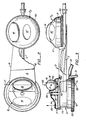
- Fig. 1 is a perspective schematic showing a pool with a cover with the pool cleaning device operating under the surface;
- Fig. 2 is a plan view of the pool cleaning device with the housing between the floats partially broken away; and,
- Fig. 3 is a side elevation in partial section illustrating the pool cleaning device.
- Referring to Fig. 1 a perspective view of the floating pool cleaning device of this invention is illustrated. A forward section A and a rear section B are interconnected by a pipe C and stream line housing D. A first overlying buoyant caster E1 over overlies forward section A. A second overlying buoyant caster E2 overlies section B. Each of the respective casters El, E2 includes a
ramp 14,wheel 16 and defines inwardly thereof the buoyant portion of the pool cleaning mechanism. When theramp 14 andwheel 16 encounter acover 20 and associated discontinuities such as pool mountedladder 23,cover fold 24,cover tear 25 and/or coveredge 26, under cover pool cleaning continues on a substantially uninterrupted basis. - Referring to Figs. 2 and 3, the particular pool cleaning device here illustrated is the device sold under the registered trademark "Pool Sweep", a trademark of the Arneson Products Corporation of Corte Madera, California. This device is given a programmed surface floating motion to clean a pool. It includes depending
sweeping hoses disposed jet 35 impart the programmed motion of the pool cleaning device. A conventional pipe C connects forward portion A to a rear portion B. - The operation of this device is well understood and has previously been described. It will not be further discussed herein except to note that the major object of the improvement to be discussed in detail is to provide minimal interference to the device operation. Stated in simple terms, the prior art device operated in an unobstructed fashion at the air-water interface at the top of the pool. The purpose of the present invention is to have uninhibited operation at the pool cover-water interface.
- To impart understanding of the disclosed invention, we will first discuss caster E1 overlying forward portion A. Thereafter, we will discuss caster E2 overlying rear portion B and its dissimilarity in the form of
peripheral wheel 40. Finally operation of the device with reference to Fig. 1 will be set forth. - Referring to Fig. 3, forward portion A is provided with a central
vertical shaft 50.Shaft 50 includes aball bearing 52.Ball bearing 52 permits free rotation of caster El about and above forward portion A so thatwheel 16 of caster E1 trailsshaft 50 in a "wind vane" manner. - It will be noted here that the caster is inverted. This inversion is required for bearing against the
underside pool cover 20. - It will further be noted that the entire and forward leading edge of the caster housing is provided with a ramp or
slope 14. I have experimentally determined thatramp 14 is optimumally sloped in the range of 22°. Slopes from as little as 10° to as much as 40° can be utilized in a broad range with slopes from 18° to 26° being utilized in an inter- meditate range. The whole purpose of this slope is to allow encountered discontinuities to pass upward to the rolling periphery of thecaster wheel 16. Thus, I recessshaft 50 well below the surface of theslope 14 to expose the periphery ofwheel 16 to the passing cover discontinuity. - It will be noted that
ramp 14 occupies the substantial entirety of the leading portion of float El. Moreover, it terminates with just a portion ofcaster wheel 16 being exposed at its rolling surface. Typically, the elevation ofwheel 16 over theramp 14 is chosen so absent a discontinuity, the cover will depend down to the surface of the water without contacting theramp 14. When however contact withramp 14 occurs -- such as at a cover discontinuity (fold, rip, border or the like), a sliding contact upramp 14 to the surface ofcaster 16 will occur without substantially inhibiting the progress of the float. - Buoyancy of the caster fairing about
shaft 50 is important. It will be understood that the caster E1 is enclosed within a fairing F, which fairing is essentially stream lined. Like conventional fairings, low drag movement ofwheel 16 through a fluid, here water, is accommodated. - Fairing F also must accommodate during under pool cover operation buoyant and reactive forces that are not immediately apparent. For example, the sum of buoyant forces in the caster E1 about axis 50 (schematically shown as upward arrows) 61 must be in effect cancelled out by the
reactive vector 62 of thecover 20 reacting downwardly onwheel 16 incased within fairing F. - It will be noted that as in most conventional fairings,
wheel 16 is mounted upon a rotational axis 17. This axis is at an elevation so thatwheel 16 is exposed from arecess 70 in the fairing. - Since caster El is inverted,
recess 70 is also inverted. Thus it is in an ideal place for debris to accumulate. The upwardly exposedrecess 70 is provided with adebris port 72 and a spatial interval between the top of float A and the bottom 73 of the fairing. Accumulated debris between thewheels 16 and therecess 70 can pass outport 72 around the upper surface of the housing A and hence to the bottom of the pool for conventional sweeping. - The description of float E2 will not herein be laboriously repeated. Caster E2 is centrally positioned over rear portion B on a vertical axis (not shown). Its construction and operation is identical.
- It will be noted that the bottom of caster E2 is surrounded by a
wheel 40. Moreover it will be similarly noted that between the respective portions A and B there is provided an expansive vane type housing D. - I have found that with under the cover pool operation that the tendency of floating pool devices to hang up on obstructions is increased and/or magnified. This being the case, the presence of
wheel 40 to pass around vertical obstructions prevents fouling. Housing D at side edges 41, 42 decreases the chance of under pool cover cleaning device fouling on vertical obstructions between the floating sections. While these devices are not necessary for the operation of my device, I find them preferred. - Returning to Fig. 1, the operation of this apparatus can be easily understood. Specifically, the
wheels 16 of the respective casters E1, E2 bear against theunderside pool cover 20. In encountering vertical obstacles, such asladder 23,peripheral wheel 40 on caster E2 over rear portion B and the side edges of housing D atborder fold 24,tear 25, andpool cover edge 26, theramps 14 andwheels 16 enable the pool cleaning device to pass smoothly. It is important to note that the overall configuration of the inverted casters of this invention even enables passage of the device from an uncovered portion of the pool to a covered portion of the pool. - It will be apparent that this invention may be modified only as restricted by the appended claims. For example, the rear portion B may consist only of the caster.
- I have illustrated the inverted casters as being the buoyant portions of the device. This preferred but not required. Moreover, the disclosed invention can constitute a kit for the modification of existing devices such as the product illustrated herein.
Claims (11)
Priority Applications (1)
| Application Number | Priority Date | Filing Date | Title |
|---|---|---|---|
| AT82106368T ATE23597T1 (en) | 1982-03-25 | 1982-07-15 | UNDER A SWIMMING POOL COVER ROLLING POOL CLEANING DEVICE. |
Applications Claiming Priority (2)
| Application Number | Priority Date | Filing Date | Title |
|---|---|---|---|
| US06/362,008 US4434050A (en) | 1982-03-25 | 1982-03-25 | Pool cleaning device for rolling operation under pool cover |
| US362008 | 1982-03-25 |
Publications (3)
| Publication Number | Publication Date |
|---|---|
| EP0090072A2 true EP0090072A2 (en) | 1983-10-05 |
| EP0090072A3 EP0090072A3 (en) | 1984-06-06 |
| EP0090072B1 EP0090072B1 (en) | 1986-11-12 |
Family
ID=23424326
Family Applications (1)
| Application Number | Title | Priority Date | Filing Date |
|---|---|---|---|
| EP82106368A Expired EP0090072B1 (en) | 1982-03-25 | 1982-07-15 | Pool cleaning device for rolling operation under pool cover |
Country Status (10)
| Country | Link |
|---|---|
| US (1) | US4434050A (en) |
| EP (1) | EP0090072B1 (en) |
| JP (1) | JPS58168759A (en) |
| AR (1) | AR230086A1 (en) |
| AT (1) | ATE23597T1 (en) |
| AU (1) | AU547440B2 (en) |
| CA (1) | CA1192712A (en) |
| DE (1) | DE3274276D1 (en) |
| ES (1) | ES8403185A1 (en) |
| ZA (1) | ZA824944B (en) |
Families Citing this family (4)
| Publication number | Priority date | Publication date | Assignee | Title |
|---|---|---|---|---|
| USD280561S (en) | 1982-10-13 | 1985-09-10 | Arneson Products, Inc. | Pool cleaner |
| USD304505S (en) | 1986-10-02 | 1989-11-07 | Aquanaut, Inc. | Underwater pool cleaning apparatus |
| US4784171A (en) * | 1987-10-16 | 1988-11-15 | Campbell Sanford F | Pool sweep modifications |
| USD459036S1 (en) | 2000-09-08 | 2002-06-18 | The Procter & Gamble Company | Automatic liquid-containing vessel cleaning device |
Family Cites Families (8)
| Publication number | Priority date | Publication date | Assignee | Title |
|---|---|---|---|---|
| US3184764A (en) | 1963-10-22 | 1965-05-25 | Cascade Ind Inc | Swimming pool cover |
| US3718148A (en) | 1970-12-16 | 1973-02-27 | M Gibellina | Pool cleaning device |
| US3883366A (en) | 1972-01-31 | 1975-05-13 | Charles M Blumenfeld | Pool cleaner |
| US4281995A (en) * | 1975-11-06 | 1981-08-04 | Pansini Andrew L | Automatic pool cleaners |
| US4087286A (en) | 1977-01-25 | 1978-05-02 | Airwick Pool Products, Inc. | Swimming pool cleaning device |
| US4105557A (en) * | 1977-03-09 | 1978-08-08 | Weatherholt Brian R | Pool skimmer |
| US4141101A (en) | 1978-01-09 | 1979-02-27 | Gibellina Michael C | Self propelled drivehead for automatic swimming pool cleaner |
| US4461704A (en) * | 1981-11-09 | 1984-07-24 | Arneson Products, Inc. | Pool cleaning device for operation under floating pool cover |
-
1982
- 1982-03-25 US US06/362,008 patent/US4434050A/en not_active Expired - Fee Related
- 1982-07-12 ZA ZA824944A patent/ZA824944B/en unknown
- 1982-07-13 AU AU85950/82A patent/AU547440B2/en not_active Ceased
- 1982-07-15 AT AT82106368T patent/ATE23597T1/en not_active IP Right Cessation
- 1982-07-15 EP EP82106368A patent/EP0090072B1/en not_active Expired
- 1982-07-15 DE DE8282106368T patent/DE3274276D1/en not_active Expired
- 1982-08-10 AR AR290269A patent/AR230086A1/en active
- 1982-09-02 JP JP57153347A patent/JPS58168759A/en active Pending
- 1982-09-21 CA CA000411841A patent/CA1192712A/en not_active Expired
- 1982-10-08 ES ES516343A patent/ES8403185A1/en not_active Expired
Also Published As
| Publication number | Publication date |
|---|---|
| ES516343A0 (en) | 1984-03-01 |
| JPS58168759A (en) | 1983-10-05 |
| DE3274276D1 (en) | 1987-01-02 |
| US4434050A (en) | 1984-02-28 |
| ATE23597T1 (en) | 1986-11-15 |
| AU547440B2 (en) | 1985-10-17 |
| EP0090072A3 (en) | 1984-06-06 |
| ZA824944B (en) | 1983-07-27 |
| ES8403185A1 (en) | 1984-03-01 |
| AR230086A1 (en) | 1984-02-29 |
| EP0090072B1 (en) | 1986-11-12 |
| AU8595082A (en) | 1983-09-29 |
| CA1192712A (en) | 1985-09-03 |
Similar Documents
| Publication | Publication Date | Title |
|---|---|---|
| US4431538A (en) | Pool cleaning device for rolling operation under pool cover | |
| US3767055A (en) | Skimmer for a water body | |
| US4900432A (en) | Pool surface cleaner | |
| AU723519B2 (en) | Water skimmer | |
| US3416176A (en) | Unit for removing solids from tanks, reservoirs and the like | |
| US3936899A (en) | Automatic swimming pool cleaner | |
| US8869337B2 (en) | Pool cleaning device with adjustable buoyant element | |
| US3822754A (en) | Automatic swimming pool cleaner | |
| US4040864A (en) | Device and method for cleaning leaves and debris from swimming pools | |
| JPH11509156A (en) | Floating dock | |
| US20140259464A1 (en) | Pool Cleaning Device With Wheel Drive Assemblies | |
| US20100058546A1 (en) | Pool cleaner baseplate with inlet extension members and recessed wheels | |
| WO1998019029A1 (en) | Swimming pool cleaner | |
| US4776053A (en) | Swimming pool vacuum cleaner hydrofoil | |
| US6834410B2 (en) | Device and method of assembling a submersible pool cleaner | |
| DE60314655D1 (en) | FLOATING WATER SURFACE CLEANER WITH SELF DRIVE | |
| US3883366A (en) | Pool cleaner | |
| US4434050A (en) | Pool cleaning device for rolling operation under pool cover | |
| CN106428442A (en) | Water surface cleaning vessel facilitating storage and unloading of water surface floating objects | |
| US4676052A (en) | Self-propelled dredge | |
| US3626535A (en) | Sphere-supported pool suction head | |
| US20070151914A1 (en) | Floating skimmer for cleaning the surface of a body of liquid | |
| US4461704A (en) | Pool cleaning device for operation under floating pool cover | |
| US5539947A (en) | Swimming pool vacuum cleaner hydrofoil | |
| CA1042818A (en) | Oil clean-up apparatus |
Legal Events
| Date | Code | Title | Description |
|---|---|---|---|
| PUAI | Public reference made under article 153(3) epc to a published international application that has entered the european phase |
Free format text: ORIGINAL CODE: 0009012 |
|
| AK | Designated contracting states |
Designated state(s): AT BE CH DE FR GB IT LI LU NL SE |
|
| PUAL | Search report despatched |
Free format text: ORIGINAL CODE: 0009013 |
|
| AK | Designated contracting states |
Designated state(s): AT BE CH DE FR GB IT LI LU NL SE |
|
| AK | Designated contracting states |
Designated state(s): AT BE CH DE FR GB IT LI LU NL SE |
|
| 17P | Request for examination filed |
Effective date: 19841117 |
|
| GRAA | (expected) grant |
Free format text: ORIGINAL CODE: 0009210 |
|
| AK | Designated contracting states |
Kind code of ref document: B1 Designated state(s): AT BE CH DE FR GB IT LI LU NL SE |
|
| PG25 | Lapsed in a contracting state [announced via postgrant information from national office to epo] |
Ref country code: NL Effective date: 19861112 Ref country code: IT Free format text: LAPSE BECAUSE OF FAILURE TO SUBMIT A TRANSLATION OF THE DESCRIPTION OR TO PAY THE FEE WITHIN THE PRESCRIBED TIME-LIMIT;WARNING: LAPSES OF ITALIAN PATENTS WITH EFFECTIVE DATE BEFORE 2007 MAY HAVE OCCURRED AT ANY TIME BEFORE 2007. THE CORRECT EFFECTIVE DATE MAY BE DIFFERENT FROM THE ONE RECORDED. Effective date: 19861112 Ref country code: BE Effective date: 19861112 Ref country code: AT Effective date: 19861112 |
|
| REF | Corresponds to: |
Ref document number: 23597 Country of ref document: AT Date of ref document: 19861115 Kind code of ref document: T |
|
| PG25 | Lapsed in a contracting state [announced via postgrant information from national office to epo] |
Ref country code: SE Effective date: 19861130 |
|
| ET | Fr: translation filed | ||
| REF | Corresponds to: |
Ref document number: 3274276 Country of ref document: DE Date of ref document: 19870102 |
|
| NLV1 | Nl: lapsed or annulled due to failure to fulfill the requirements of art. 29p and 29m of the patents act | ||
| PG25 | Lapsed in a contracting state [announced via postgrant information from national office to epo] |
Ref country code: LU Free format text: LAPSE BECAUSE OF NON-PAYMENT OF DUE FEES Effective date: 19870731 |
|
| PLBE | No opposition filed within time limit |
Free format text: ORIGINAL CODE: 0009261 |
|
| STAA | Information on the status of an ep patent application or granted ep patent |
Free format text: STATUS: NO OPPOSITION FILED WITHIN TIME LIMIT |
|
| 26N | No opposition filed | ||
| PG25 | Lapsed in a contracting state [announced via postgrant information from national office to epo] |
Ref country code: DE Effective date: 19880401 |
|
| PGFP | Annual fee paid to national office [announced via postgrant information from national office to epo] |
Ref country code: CH Payment date: 19910730 Year of fee payment: 10 |
|
| PGFP | Annual fee paid to national office [announced via postgrant information from national office to epo] |
Ref country code: GB Payment date: 19920706 Year of fee payment: 11 |
|
| PG25 | Lapsed in a contracting state [announced via postgrant information from national office to epo] |
Ref country code: LI Effective date: 19920731 Ref country code: CH Effective date: 19920731 |
|
| REG | Reference to a national code |
Ref country code: CH Ref legal event code: PL |
|
| PGFP | Annual fee paid to national office [announced via postgrant information from national office to epo] |
Ref country code: FR Payment date: 19930709 Year of fee payment: 12 |
|
| PG25 | Lapsed in a contracting state [announced via postgrant information from national office to epo] |
Ref country code: GB Effective date: 19930715 |
|
| GBPC | Gb: european patent ceased through non-payment of renewal fee |
Effective date: 19930715 |
|
| PG25 | Lapsed in a contracting state [announced via postgrant information from national office to epo] |
Ref country code: FR Effective date: 19950331 |
|
| REG | Reference to a national code |
Ref country code: FR Ref legal event code: ST |