EP0093628B1 - Steckdose mit mehreren Kontaktelementen - Google Patents
Steckdose mit mehreren Kontaktelementen Download PDFInfo
- Publication number
- EP0093628B1 EP0093628B1 EP83400665A EP83400665A EP0093628B1 EP 0093628 B1 EP0093628 B1 EP 0093628B1 EP 83400665 A EP83400665 A EP 83400665A EP 83400665 A EP83400665 A EP 83400665A EP 0093628 B1 EP0093628 B1 EP 0093628B1
- Authority
- EP
- European Patent Office
- Prior art keywords
- plug
- female
- complementary
- male
- seatings
- Prior art date
- Legal status (The legal status is an assumption and is not a legal conclusion. Google has not performed a legal analysis and makes no representation as to the accuracy of the status listed.)
- Expired
Links
- 230000000295 complement effect Effects 0.000 claims description 38
- 230000008878 coupling Effects 0.000 claims description 11
- 238000010168 coupling process Methods 0.000 claims description 11
- 238000005859 coupling reaction Methods 0.000 claims description 11
- 238000005192 partition Methods 0.000 claims description 4
- 230000000149 penetrating effect Effects 0.000 claims 1
- 238000009434 installation Methods 0.000 description 4
- 238000012423 maintenance Methods 0.000 description 3
- 229920003023 plastic Polymers 0.000 description 3
- 230000006378 damage Effects 0.000 description 2
- 239000011810 insulating material Substances 0.000 description 2
- 239000000463 material Substances 0.000 description 2
- 241001080024 Telles Species 0.000 description 1
- 230000002159 abnormal effect Effects 0.000 description 1
- 230000015556 catabolic process Effects 0.000 description 1
- 235000009508 confectionery Nutrition 0.000 description 1
- 238000010586 diagram Methods 0.000 description 1
- 238000003780 insertion Methods 0.000 description 1
- 230000037431 insertion Effects 0.000 description 1
- 238000007689 inspection Methods 0.000 description 1
- 230000014759 maintenance of location Effects 0.000 description 1
- 238000004519 manufacturing process Methods 0.000 description 1
- 230000035515 penetration Effects 0.000 description 1
- 239000004065 semiconductor Substances 0.000 description 1
- 238000012795 verification Methods 0.000 description 1
- 238000004804 winding Methods 0.000 description 1
Images

Classifications
-
- H—ELECTRICITY
- H01—ELECTRIC ELEMENTS
- H01R—ELECTRICALLY-CONDUCTIVE CONNECTIONS; STRUCTURAL ASSOCIATIONS OF A PLURALITY OF MUTUALLY-INSULATED ELECTRICAL CONNECTING ELEMENTS; COUPLING DEVICES; CURRENT COLLECTORS
- H01R13/00—Details of coupling devices of the kinds covered by groups H01R12/70 or H01R24/00 - H01R33/00
- H01R13/64—Means for preventing incorrect coupling
- H01R13/645—Means for preventing incorrect coupling by exchangeable elements on case or base
-
- H—ELECTRICITY
- H01—ELECTRIC ELEMENTS
- H01R—ELECTRICALLY-CONDUCTIVE CONNECTIONS; STRUCTURAL ASSOCIATIONS OF A PLURALITY OF MUTUALLY-INSULATED ELECTRICAL CONNECTING ELEMENTS; COUPLING DEVICES; CURRENT COLLECTORS
- H01R33/00—Coupling devices specially adapted for supporting apparatus and having one part acting as a holder providing support and electrical connection via a counterpart which is structurally associated with the apparatus, e.g. lamp holders; Separate parts thereof
- H01R33/74—Devices having four or more poles, e.g. holders for compact fluorescent lamps
- H01R33/76—Holders with sockets, clips, or analogous contacts adapted for axially-sliding engagement with parallely-arranged pins, blades, or analogous contacts on counterpart, e.g. electronic tube socket
- H01R33/7657—Holders with sockets, clips, or analogous contacts adapted for axially-sliding engagement with parallely-arranged pins, blades, or analogous contacts on counterpart, e.g. electronic tube socket characterised by keying or marking means
Definitions
- the present invention refers, as indicated in the description of this specification, to a series of improvements made to the coding systems of female sockets with multiple terminals, intended not only to obtain such codification relating each male socket multiple to the corresponding socket, otherwise also to ensure the practical impossibility of coupling between elements of different code.
- a universal arrangement adopted for some time is that which includes eight or eleven male plugs of cylindrical configuration, of standardized diameter, arranged in correspondence with an imaginary cylindrical surface, of radius also standardized, these male sockets being known in Spain as “octals” or “undecals”, depending on whether they include eight or eleven male plugs.
- the sockets of the female socket are connected by means of cables or other systems to screw terminals for the rear wiring of the female sockets, or these cables are soldered directly to the sockets in question.
- connection system also standardized, so that, if it is a relay for example, the terminals of the coil are always connected to the same plugs of the multiple male plug, as happens with open contacts, closed contacts, switch contacts, etc., using universally accepted connection diagrams and according to international standards.
- connection socket comprising a male part and a female part in which are formed a circular groove and a series of separate, axial and circumferential slots.
- a curved blade carries in its center a vertical part which can be inserted into one of the slots to determine the position of the blade.
- the male part comprises a blade and slots and the connection with the female part is carried out by bringing the respective blades of the male and female parts into opposite slots.
- these male plugs are provided with a central projection having the shape of a cylinder provided with a key, while the female sockets have, in correspondence with the previous structure, a cylindrical housing and a groove or notch on one of its generatrices to receive said key.
- the device carrying the multiple male plug can only adapt to the female plug in a determined position.
- the plugs of the male plug are listed clockwise, starting from the key, from one to eight or from one to eleven as appropriate, and the sockets or female plugs of the female plug are listed from the same way, as well as the usage terminals connected to these sockets. In this way, the user knows that when he connects a cable to terminals 2 and 10 of the female socket, this connection continues, via the female plug-male plug contact, to the terminals of the relay coil. .
- the connection systems of the plugs of the plugs which are standardized in the case of relays, also follow very standardized criteria in the case of timers and other electronic devices.
- this standardized coding system which is theoretically correct, is insufficient and presents problems in the practice of mounting and maintaining electrical equipment. triques, by allowing errors which are sometimes the cause of significant secondary failures, or which hamper the normal functioning of the equipment in question.
- a relay whose coil is designed for working at 24 volts can, for example, be adjusted so that the operating voltage is 13 volts, the retention voltage of 5 volts and the operating time of 10 milliseconds .
- this relay is replaced by another whose coil is also marked as being 24 volts, but with different settings, nothing prevents this second relay from being connected to the socket of the first, but it It is obvious that the same working conditions will not be given.
- the relay will operate at a different voltage, with different times, so it is easy for an intermittent fault to occur in equipment requiring costly overhaul.
- the invention relates to a socket having the characteristics set out in claim 1.
- the actual coding is carried out on the one hand thanks to the cooperation of two complementary parts, one intended to be fixed to the female socket and the other to the multiple male socket, and, on the other hand, to the relative positioning of the housings and sockets, so that it is only when these two parts are complementary that one can install the mechanism in question on said socket, while in any other circumstance this proves impossible , even if the two elements are provided with the same number of male and female plugs and in the same arrangement.
- the complementary parts can be made, for example, by a small rod coupling in one of the complementary housings of the female plug, while a disc made of insulating material is adapted to the multiple male plug. , preferably provided with holes for coupling to the male plugs of this multiple socket, this disc further comprising other plugs, also made of insulating material, intended to snap into the complementary housings of the female socket, this number of male plugs being equal to the number of male plugs of real connection of the multiple socket minus one.
- This disc can obviously be mounted on the male multiple socket in different positions, in correspondence with the number of male connection plugs existing on the latter, while the first part, associated with the female socket, can also occupy different positions on the latter. concretely coinciding in number with that of the complementary housings, which itself coincides, as we saw above, with that of the connection sockets.
- a double coding is established, on the one hand that determined by the own multiple male plug and the complementary female sockets of the female plug, assisted by the conventional key housing, and on the other hand a coding determined by the position of the two aforementioned complementary parts, relative to the male plug multiple and to the female socket, determining that a male socket can only be coupled to a female socket when their coding coincides, which solves the problem of possible errors to which we alluded above.
- the female socket proposed by the invention has all its connection terminals housed in cavities where they are perfectly protected against any occasional contact, and in addition, their online arrangement making that they are perfectly isolated from each other, any possibility of short circuit is practically zero.
- the length of the cable which has to enter the socket is absolutely identical in all cases, which also facilitates wiring.
- the identification numbers of the various terminals are also arranged online, which also makes them particularly convenient to read, a phenomenon which is particularly advantageous when there are various female sockets mounted on a common support and leaning against each other.
- Another characteristic of the socket proposed by the invention consists in the fact that, coinciding with each of its connection terminals, or what amounts to the same thing, with each of the female terminals or sockets, there are small holes fitting out access for a test point of a measuring device, to the corresponding terminals, with the particularity that this test point remains fixed in these holes and thus maintains the contact situation, thus leaving the hands of the user free operator for any other type of manipulation necessary for the verification operations to be carried out.
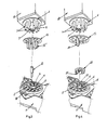
- a female socket 1 will comprise, between its circular alignment of housings 2-corresponding to the receptacles of male plugs 3 of the male multiple socket 4-and its central orifice 5-with its corresponding groove 6 for receiving the cylindrical appendage 7 of the male multiple socket 4, appendage provided with a key 8- a plurality of complementary housings 9 preferably coinciding in number with that of the sockets 2, which will be also preferably determined by radial partition-partitions 10 connecting an inner ring 11 constituting and delimiting the own axial orifice 5, and the body on which the housings of the sockets are formed.
- the part 12 constitutes a wedge intended to snap into any of the housings 9 of the socket, while the part 13 is configured by a disc having the same reference 13, provided with holes 14, to be fixed to the own multiple male socket 4, specifically to the male plugs 3 thereof, this disc or ring 13 having a hollow cylindrical extension 15, the diameter of which coincides with that of the circular alignment of the housings 9, this cylindrical projection having a free end crenellated, so that each of the slots 16 thus determined can penetrate one of the housings 9 of the socket, one of the missing slots leaving room for a large integral cutout 17 or groove which, in the correct position mounting between the male multiple socket and the female socket, in accordance with the codification provided - is located opposite the shim 12 associated with the female socket whereas, in any other coupling position of the male socket and the female socket , one of the slots 16 will abut against the wedge 12 and will make any coupling between these elements impossible, which will allow the operator to realize that the element or device 18 associated with the male connector 4, in accordance with the coding previously established on the female
- the shim 12 can keep the same configuration as in the previous case, but the disc 13, instead of comprising a cylindrical and hollow projection 15 as before, comprises a series of plugs 16 'corresponding to the slots 16 above, which themselves corresponded to the complementary housings 9 of the socket, one of these plugs 16 'being absent and leaving room for the integral cutout or groove 17 of the previous case.
- the body 1 of the socket has its connection terminals arranged in two transverse and extreme alignments, in correspondence with the reference housings 22 in the figures, housings perfectly independent of each other thanks to partitions 23 which eliminate any possibility of a short circuit between the cables having access to these terminals, access taking place precisely through the openings 24 formed between each pair of partitions 23.
- the identification numbers 26 of these terminals are also arranged transversely and in line, which makes them easy to read, especially when there are several female sockets mounted next to each other.
- the socket outlet which is the subject of the invention is provided with its own identification system, which system is also double.
- housings 27 On one side of its front face are housings 27 in which can be embedded numbered plastic parts, commercial, which fit together by exerting pressure and which include graphics consisting of numbers or letters which, duly combined, allow the sought identification of the socket in question.
- a second aspect of this identification system consists of a card 28 covered with a transparent plastic plate, which is fixed to the front face of the body 1 by means of two end plugs 29 therein and which can be see in detail in FIG. 1, by simple pressure, as well as in the symmetrical zone of the front face of the body, in this same FIG. 1.
- this card or label 28 can bear any code whatsoever making it possible to identify the socket in all of the components forming the electrical equipment of an installation.
- connection terminals 25 there are small holes 30 also providing access to the terminals in question and allowing the introduction of a test tip of a measuring device, during possible inspections of the electrical equipment and its maintenance.
- These holes 30 have for concrete and specific purpose, that of adapting as to their dimensions to the test tips so that they remain in contact position and the terminals in a stable manner, leaving the hands free. operator, which implies a considerable practical advantage over sockets conventional females where the test points must be adapted to the own screws 25, which means that the worker must hold these points in one hand permanently because, otherwise, the connection would be interrupted.
Landscapes
- Details Of Connecting Devices For Male And Female Coupling (AREA)
Claims (6)
Applications Claiming Priority (4)
| Application Number | Priority Date | Filing Date | Title |
|---|---|---|---|
| ES51182182 | 1982-04-29 | ||
| ES511821 | 1982-04-29 | ||
| ES264939U | 1982-05-04 | ||
| ES1982264939U ES264939Y (es) | 1982-05-04 | 1982-05-04 | "base de enchufe perfeccionada". |
Publications (3)
| Publication Number | Publication Date |
|---|---|
| EP0093628A2 EP0093628A2 (de) | 1983-11-09 |
| EP0093628A3 EP0093628A3 (en) | 1986-03-26 |
| EP0093628B1 true EP0093628B1 (de) | 1989-01-04 |
Family
ID=26155506
Family Applications (1)
| Application Number | Title | Priority Date | Filing Date |
|---|---|---|---|
| EP83400665A Expired EP0093628B1 (de) | 1982-04-29 | 1983-03-30 | Steckdose mit mehreren Kontaktelementen |
Country Status (2)
| Country | Link |
|---|---|
| EP (1) | EP0093628B1 (de) |
| DE (1) | DE3378876D1 (de) |
Families Citing this family (8)
| Publication number | Priority date | Publication date | Assignee | Title |
|---|---|---|---|---|
| DE3630451C3 (de) * | 1986-09-06 | 1994-12-22 | Eaton Controls Gmbh | Elektrische Mehrfach-Steckverbindung |
| FR2680608B1 (fr) * | 1991-08-21 | 1993-10-08 | Marechal Expl Procedes | Dispositif selectif de connexion electrique muni d'un disque de securite et d'un disque complementaire. |
| FR2680607B1 (fr) * | 1991-08-21 | 1994-11-10 | Marechal Sepm | Dispositif selectif de connexion electrique muni d'un disque de securite. |
| DE29615140U1 (de) * | 1996-08-30 | 1996-10-17 | HTS-Elektrotechnik GmbH, 53819 Neunkirchen-Seelscheid | Einpolige Laststeckverbinderkombination |
| GB2428524B (en) * | 2005-07-19 | 2010-03-17 | Seymour Design Ltd | A lamp holder and lamp end cap for a low-energy lamp |
| US9225116B2 (en) | 2013-07-23 | 2015-12-29 | Tyco Electronics Corporation | Quick connect power connector isolating system |
| US9059542B2 (en) | 2013-07-23 | 2015-06-16 | Tyco Electronics Corporation | Quick connect power connector |
| US9190784B1 (en) | 2014-07-21 | 2015-11-17 | Tyco Electronics Corporation | High performance contact element |
Family Cites Families (8)
| Publication number | Priority date | Publication date | Assignee | Title |
|---|---|---|---|---|
| FR977303A (fr) * | 1948-11-08 | 1951-03-30 | Perfectionnements apportés aux prises de courant à combinaisons multiples | |
| GB947776A (en) * | 1960-07-12 | 1964-01-29 | Fernand Georges Bac | Improvements in multi-pin, plug-and-socket, electric couplings |
| DE1250515B (de) * | 1962-01-18 | 1900-01-01 | ||
| FR1331988A (fr) * | 1962-05-03 | 1963-07-12 | Perfectionnements apportés au raccord de jonction pour conducteurs électriques | |
| CH396279A (de) * | 1962-09-24 | 1965-07-31 | Landis & Gyr Ag | Steckbares Steuerungsgerät |
| FR1344601A (fr) * | 1962-11-28 | 1963-11-29 | Pyle National Co | Connecteur à clavettes pouvant tourner pas à pas |
| US3447036A (en) * | 1967-04-21 | 1969-05-27 | Bell Telephone Labor Inc | Assembly for mounting and aligning modules |
| BE757099A (fr) * | 1969-10-15 | 1971-03-16 | Bunker Ramo | Connecteur electrique |
-
1983
- 1983-03-30 EP EP83400665A patent/EP0093628B1/de not_active Expired
- 1983-03-30 DE DE8383400665T patent/DE3378876D1/de not_active Expired
Also Published As
| Publication number | Publication date |
|---|---|
| DE3378876D1 (en) | 1989-02-09 |
| EP0093628A3 (en) | 1986-03-26 |
| EP0093628A2 (de) | 1983-11-09 |
Similar Documents
| Publication | Publication Date | Title |
|---|---|---|
| EP0093628B1 (de) | Steckdose mit mehreren Kontaktelementen | |
| FR2748862A1 (fr) | Dispositif pour raccorder un cable coaxial a une carte de circuit imprime | |
| FR2720554A1 (fr) | Dispositif détrompteur pour une paire de modules à accoupler, notamment pour des connecteurs électriques complémentaires. | |
| FR2866485A1 (fr) | Partie de connecteur electrique etanche. | |
| EP0018552A1 (de) | Verriegelungsvorrichtung für Verbinder | |
| FR2670294A1 (fr) | Prise test. | |
| EP0986842B1 (de) | Ring zur kennzeichnung der betriebsspannung eines elektrischen steckverbinderelementes | |
| EP0592287A1 (de) | Schnappverbinder für optische Fasern, insbesondere umgossener Stecker | |
| EP0889565A1 (de) | Gehäuse für elektrische anlage | |
| WO2023002096A1 (fr) | Dispositif de connexion d'un terminal d'un module de batterie à un conducteur électrique | |
| EP0459908A1 (de) | Coaxialkabelverbinder | |
| EP0691712A1 (de) | Kupplungsvorrichtung für zwei Module und ihre Anwendung für komplementäre Verbinder | |
| EP0245329A1 (de) | Dezentralisierte verbindungsanordnung eines organs a eine programmierbare regeleinheit | |
| FR2500224A1 (fr) | Plinthe pouvant recevoir des conducteurs electriques et permettant l'insertion d'une fiche en tout point desire | |
| FR2824426A1 (fr) | Element de connecteur electrique coaxial | |
| EP2874244B1 (de) | Elektrischer Anschluss mit modulierbarer Kodierung | |
| FR2913540A1 (fr) | Appareillage electrique a connexions electriques automatiques priorisees | |
| EP1794770B1 (de) | Verbinder zum verbinden eines kabelleiters mit einem leitendem stab oder einem sicherungseinsatz und verteilerkasten mit solch einem verbinder | |
| EP0797271B1 (de) | Sockel für Stromsteckdose | |
| EP0720190A1 (de) | Trägermodul für mechanisch-elektrische Bauteile | |
| FR2579016A1 (fr) | Interrupteur a commande electromagnetique | |
| KR20240156724A (ko) | 전원콘센트 어셈블리 | |
| CH364826A (fr) | Fiche pour le raccordement électrique d'un appareil | |
| FR2490043A1 (fr) | Interrupteur limiteur actionnable sans contact | |
| EP0779691B1 (de) | Sicherheitskupplungsanordnung für eine Mehrheit von elektrischen, modularen Geräten |
Legal Events
| Date | Code | Title | Description |
|---|---|---|---|
| PUAI | Public reference made under article 153(3) epc to a published international application that has entered the european phase |
Free format text: ORIGINAL CODE: 0009012 |
|
| AK | Designated contracting states |
Designated state(s): BE DE FR GB IT NL SE |
|
| 17P | Request for examination filed |
Effective date: 19831117 |
|
| PUAL | Search report despatched |
Free format text: ORIGINAL CODE: 0009013 |
|
| AK | Designated contracting states |
Kind code of ref document: A3 Designated state(s): BE DE FR GB IT NL SE |
|
| 17Q | First examination report despatched |
Effective date: 19870302 |
|
| GRAA | (expected) grant |
Free format text: ORIGINAL CODE: 0009210 |
|
| AK | Designated contracting states |
Kind code of ref document: B1 Designated state(s): BE DE FR GB IT NL SE |
|
| REF | Corresponds to: |
Ref document number: 3378876 Country of ref document: DE Date of ref document: 19890209 |
|
| ITF | It: translation for a ep patent filed | ||
| GBT | Gb: translation of ep patent filed (gb section 77(6)(a)/1977) | ||
| PLBE | No opposition filed within time limit |
Free format text: ORIGINAL CODE: 0009261 |
|
| STAA | Information on the status of an ep patent application or granted ep patent |
Free format text: STATUS: NO OPPOSITION FILED WITHIN TIME LIMIT |
|
| 26N | No opposition filed | ||
| PGFP | Annual fee paid to national office [announced via postgrant information from national office to epo] |
Ref country code: BE Payment date: 19930122 Year of fee payment: 11 |
|
| PGFP | Annual fee paid to national office [announced via postgrant information from national office to epo] |
Ref country code: SE Payment date: 19930212 Year of fee payment: 11 |
|
| PGFP | Annual fee paid to national office [announced via postgrant information from national office to epo] |
Ref country code: FR Payment date: 19930224 Year of fee payment: 11 |
|
| PGFP | Annual fee paid to national office [announced via postgrant information from national office to epo] |
Ref country code: GB Payment date: 19930319 Year of fee payment: 11 |
|
| ITTA | It: last paid annual fee | ||
| PGFP | Annual fee paid to national office [announced via postgrant information from national office to epo] |
Ref country code: NL Payment date: 19930331 Year of fee payment: 11 |
|
| PGFP | Annual fee paid to national office [announced via postgrant information from national office to epo] |
Ref country code: DE Payment date: 19930601 Year of fee payment: 11 |
|
| PG25 | Lapsed in a contracting state [announced via postgrant information from national office to epo] |
Ref country code: GB Effective date: 19940330 |
|
| PG25 | Lapsed in a contracting state [announced via postgrant information from national office to epo] |
Ref country code: SE Free format text: LAPSE BECAUSE OF NON-PAYMENT OF DUE FEES Effective date: 19940331 Ref country code: BE Effective date: 19940331 |
|
| BERE | Be: lapsed |
Owner name: LOZANO RICO SANTIAGO Effective date: 19940331 |
|
| PG25 | Lapsed in a contracting state [announced via postgrant information from national office to epo] |
Ref country code: NL Effective date: 19941001 |
|
| NLV4 | Nl: lapsed or anulled due to non-payment of the annual fee | ||
| GBPC | Gb: european patent ceased through non-payment of renewal fee |
Effective date: 19940330 |
|
| PG25 | Lapsed in a contracting state [announced via postgrant information from national office to epo] |
Ref country code: FR Effective date: 19941130 |
|
| PG25 | Lapsed in a contracting state [announced via postgrant information from national office to epo] |
Ref country code: DE Effective date: 19941201 |
|
| REG | Reference to a national code |
Ref country code: FR Ref legal event code: ST |
|
| EUG | Se: european patent has lapsed |
Ref document number: 83400665.2 Effective date: 19941010 |