EP0097317B1 - Lichtschranke - Google Patents
Lichtschranke Download PDFInfo
- Publication number
- EP0097317B1 EP0097317B1 EP83105836A EP83105836A EP0097317B1 EP 0097317 B1 EP0097317 B1 EP 0097317B1 EP 83105836 A EP83105836 A EP 83105836A EP 83105836 A EP83105836 A EP 83105836A EP 0097317 B1 EP0097317 B1 EP 0097317B1
- Authority
- EP
- European Patent Office
- Prior art keywords
- housing part
- housing
- light barrier
- barrier apparatus
- tubular spigot
- Prior art date
- Legal status (The legal status is an assumption and is not a legal conclusion. Google has not performed a legal analysis and makes no representation as to the accuracy of the status listed.)
- Expired
Links
Images

Classifications
-
- G—PHYSICS
- G01—MEASURING; TESTING
- G01V—GEOPHYSICS; GRAVITATIONAL MEASUREMENTS; DETECTING MASSES OR OBJECTS; TAGS
- G01V8/00—Prospecting or detecting by optical means
- G01V8/10—Detecting, e.g. by using light barriers
- G01V8/12—Detecting, e.g. by using light barriers using one transmitter and one receiver
- G01V8/14—Detecting, e.g. by using light barriers using one transmitter and one receiver using reflectors
Definitions
- the invention relates to a light barrier apparatus comprising a housing, at least one photoelectric converter, at least one front lens arranged in a wall of the housing, an electronic circuit connected to said at least one photoelectronic converter, power supply lines leading from power supply terminals to said electronic circuit, and also in the case of a receiver or a transmitter/receiver, signal lines and signal terminals.
- Customary light barrier apparatus is almost always constructed so that the optical parts are fixed components of the housing.
- the optical axis can thus neither be changed nor adjusted relative to the axes of the housing.
- An appropriate mount is required in order to allow the optical axis or the optical axes of light barrier apparatus of this kind to be aligned with a retroreflector, or in the case of a single path light barrier, to allow the transmitter to be aligned with the receiver and vice versa.
- Light barrier apparatus is also already known in which the optical axis can be adjusted relative to the housing through a relatively small angular range. It is a disadvantage of the previously named kind of light barrier that the range of angular adjustment of the optical axis is relatively restricted. It is desirable, in particular with light barriers with a working range of up to hundreds of meters and with small transmission and reception cones, also to have the possibility of adjusting them through larger angular ranges. At the same time the housing should however, also be of compact construction and be capable of being sealed in a gastight and watertight manner against the external environment.
- An object of the invention is to provide an adjustment system which does not suffer the disadvantages of the adjustment system of US-A-3,679,906.
- light barrier apparatus comprising a housing, at least one photoelectric converter, at least one front lens arranged in a wall of said housing, an electronic circuit connected to said at least one photoelectronic converter power supply lines leading from power supply terminals to said electronic circuit, and also, in the case of a receiver or a transmitter/receiver signal lines and signal terminals; wherein the housing is subdivided into first and second housing parts which are pivotably connected together by a coupling permitting relative pivotal movement between said first and second housing parts about at least one pivot axis and preferably about two mutually perpendicular pivot axes; wherein said first part contains, at least in large part, said electronic circuit, including said power supply lines, power supply terminals and, if present, said signal lines and signal terminals; wherein said second housing part contains at most a part of said electronic circuit, said photoelectronic converter and also said front lens; wherein said coupling between said first and second
- the second housing part can contain either only a light transmitter, or only a light receiver, or both a light transmitter and a light receiver. In the latter case the light barrier apparatus cooperates with a retroreflector arranged at a distance therefrom.
- the first housing part thus requires only the simplest of securing means because it only needs to be immovably attached to a support.
- the connections can consist of cable connections, clamped connections or plugged connections. Any adjustment or indicating elements that are required should be provided in the first housing part.
- the optical and photoelectronic components (light source, light receiver in the form of a photoelectronic converter) are consciously not provided in the first housing part.
- the second housing part which despite the articulated coupling can also be locked in any desired position relative to the first housing part, carries at least the front lens, or with an autocollimation light barrier the front lenses, and the photoelectronic component(s) (for example a luminous diode or a photoelectric converter). If necessary, parts of the receiver amplifier can also be housed in the second housing part.
- the coupling between the two housing parts has a purely mechanical function however also serves to accommodate the electrical connection lines between the two housing parts.
- the coupling is preferably so arranged that the inner spaces of the two housing parts are indeed connected together but are sealed against the external environment.
- a particularly preferred embodiment is constructed so that said coupling defines first and second pivot axes of which said first pivot axis is defined by said cooperating curved slide surfaces and extends parallel to said end wall and said second pivot axis extends at right angles to said end end wall and coincides with the central longitudinal axis of said tubular spigot.
- the invention envisages that the tubular spigot has a concave right cylindrical guide surface at its outer end, said concave guide surface contacting a complementary, convex, right cylindrical guide surface at the underside of said second housing part, with said convex guide surface being concentric to said first pivot axis; and that said fixing means comprises a holder rotatably secured to the tubular spigot, said holder supporting said second housing part for pivotal movement about said second pivot axis.
- the holder is preferably a clamping ring and two retaining arms for the pivotal attachment of said second housing part about the second pivot axis are arranged on said holder.
- an advantageous further development of this embodiment is constructed so that the clamping ring is braced at one side against the neighbouring end wall of the first housing part and at the other side against an inclined annular surface of an end flange of the tubular spigot, in such a way that as the clamping of the clamp ring increases the tubular spigot is subjected to an increasing tension in the direction towards the second housing part.
- the second housing part has substantially the shape of a parallelepiped, preferably with a rounded rear wall.
- a further embodiment is characterised in that the sidewalls, and also the front and rear walls, of the second housing part do not project beyond the side, front and rear walls of the first housing part when aligned therewith and are preferably flush therewith.
- the two housing parts jointly for a compact arrangement which resembles a single housing, however despite this the aforementioned adjustability and lockability are ensured.
- the tubular spigot is drawn towards the first housing part by a nut disposed within said first housing part and screwed onto an end thread of the tubular spigot; and the tubular spigot has a flange inside the second housing part, with the flange pressing a convex spherical surface concentric with the second pivot axis from the inside against a complementary concave spherical surface at the end wall of the first housing part.
- a post and a cooperating elongate . groove into which said post projects can be provided, with said groove forming end abutments for said post to restrict the. range of relative rotation of said housing parts.
- a light barrier apparatus which cooperates with a retroreflector (not shown) is equipped with a light emitting diode 17 and a photoelectric converter 18.
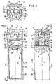
- the light barrier apparatus has a first housing part 11 in the form of a parallelepiped and a second housing part 12 which is substantially aligned with the first housing part 11 and connected thereto via a universal coupling 15.
- the front wall 26 of the housing has been omitted in Fig. 1 in order to show the inner chamber 44 provided for accommodating the electronic circuit including the power supply lines, the power supply terminals, and also the signal lines and the signal terminals. All these assemblies have however been omitted from this inner space 44 for the purpose of illustration.
- the housing has two sidewalls, which are likewise rectangular in the illustrated manner, and also a rear wall 25 and two square end walls 20, 27.
- a circular bore 31 is provided in the upper end wall 20 of the first housing part 1-1.
- a tubular spigot 30 extends upwardly through this circular bore coaxially to the axis 29 of the housing part 11.
- An abutment ring 32 sits in an annular groove 45 at the lower end of the tubular spigot 30. The diameter of the abutment ring 32 is larger than that of the bore 31 and the ring contacts the end wall 20 from beneath.
- tubular spigot 30 At its upper end the tubular spigot 30 has an annular flange 38 the end face of which remote from the housing part 11 is constructred as a right cylindrical slide surface 33 with the axis 28 as the axis of the. cylinder.
- the second housing part contains a chamber 46 which receives a partition wall 47 in which the light emitting diode 17 and the photoelectric converter are arranged in the illustrated manner.
- the front side of the housing part 12 is closed by two front lenses 13, 14 which are constructed as a unit with the light emitting diode 17 and the photoelectric converter 18 being located at the focal points of the two front lenses.
- the sidewalls 21 and also the front and rear walls 22 and 23 of the second housing part 12 are aligned in the position shown in Figs. 1 and 2 with the front and rear walls 25, 26 of the first housing part 11.
- the rear wall 22 of the second housing part 12, which likewise has substantially the shape of a parallelepiped, is rounded in the manner which can be seen in Fig. 2.
- the second housing part 12 has lateral bores 48 (Fig. 3).
- Pivots 49 supported by lateral retaining arms 36 engage in the lateral bores 48.
- the lateral retaining arms are formed on a holder constructed as a clamping 35 and extend parallel to the central axis 29 of the two housing parts 11, 12.
- the pivots 49 can be formed on headed pins which engage in corresponding bores in the retaining arms 36.
- the clamping ring 35 has a clamping slot 51 which is bridged by a clamping screw 50 and surrounds the tubular spigot 30, which has an axial passage 16 for accommodating the connection lines 19 indicated in Fig. 2.
- the flange 38 of the tubular spigot 30 has an inclined annular surface 37, which can be seen in Fig. 2, at its lower edge which faces the first housing part 11.
- This inclined annular surface 37 cooperates with a mating counter-surface of the clamping ring 35.
- the other endface of the clamping ring 35 contacts the end wall 20, or a projection 20' arranged thereon.
- the upper end surface of the clamping ring ' 35 slides along the annular inclined surface 37 of the flange 38 of the tubular spigot 30 so that the clamping ring is braced against the end wall 20 or the projection 20' of the lower housing part 11.
- the tubular spigot 30 is drawn upwardly away from the first housing part 11 and the abutment ring 32 securely contacts the end wall 20.
- the abutment ring 32 can also be provided with sealing characteristics so that this pressure results in a reliable seal of the inner chamber 44 of the first housing part against the external environment.
- the lateral retaining arms 36 are accommodated in lateral recesses 53 of the second housing part 12 so that they do not project externally beyond the sidewalls 21, 24 of the housing parts 11, 12.
- the lateral recesses 53 are more or less of sector-like construction so that the second housing part 12, can be pivoted as far as desired about the second pivot axis 28.
- the corners of the second housing part are preferably shaped in the manner illustrated in perspective in Fig. 7. Accordingly attachment projections 56 which do not project beyond the walls, and which are of smaller depth than the walls, are proviced at the four corners. Attachment bores 54 are arranged in the attachment projections 56 and securing bolts 55 can be inserted through these attachment bores to secure the housing part 12 to a wall or other support (not illustrated).
- the second housing part 12 is accurately aligned with the associated retroreflector by pivotal movement about the axes 28, 29.
- the screw 50 is subsequently tightened whereupon the selected adjustment is fixed and the relatively movable surfaces of the housing parts 11 and 12 and of the universal coupling 15 are sealingly pressed together.
- the assembly of the light barrier apparatus is expediently effected by first inserting the tubular spigot 30 from above into the clamping ring 30 and then pushing it through the end wall 20.
- the abutment ring 32 is then mounted and the second housing part 12 attached to the retaining arms 36.
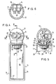
- the second housing part 12 is of substantially spherical shape with the two pivot axes 28, 29 intersecting at the center of the spherical housing 12.
- the front lenses 13, 14 are arranged alongside one another in the wall of the spherical housing part 12 and the light emitting diode 17 and the photoelectric converter 18 are arranged in the manner shown in the drawing behind the front lenses 13, 14.
- the housing part 12 At its side facing the first housing part 11 the housing part 12 has a convex spherical surface 42 which contacts a complementary concave spherical surface 43 which is formed at the side of the end wall 20 facing the housing part 12.
- a sealing ring 48 is arranged in an annular groove 57 of the concave spherical surface 43. The sealing ring 58 contacts the convex spherical surface 42 and seals the movable surfaces against the external environment.
- the tubular spigot 30 extends again through the bore 31 in the end wall 20.
- a sealing disk 59 is pressed against the lower side of the end wall 20 by a nut 39 screwed onto a thread 40 of the tubular spigot 30.
- the tubular spigot 30 has a flange 41 which contacts a surface surrounding a circular opening 60 of the housing part 12 from the inside. In this manner the convex spherical surface 42 of this spherical housing part 12 is pressed against the concave spherical surface 43 of the housing part 11 via the spring flange 41 on tightening the nut 39.
- the spherical housing 12 can be pivoted against a preadjustable resistance around the pivot axes 28 or 29.
- the possible pivot angle about the transverse axis 28 is determined in this arrangement by the size of the circular opening 60.
- a restricted peripheral groove 10 is located in the flange 41 and copperates with an inwardly projecting post 9 of the housing part 12.
- the post 9 meets end abutments on rotation of the housing part 12 about the axis 29.
- the range of rotation of the housing part 12 can be restricted in this way to a desired value.
- the lower housing part 11 has an upwardly projecting post 9' which engages in a circular groove 10' at the lower side of the upper housing part 12.
- the groove 10' is also restricted in the peripheral direction in order to limit the range of pivotal movement of the housing 12 at both sides.
- the seal between the two parts of the housing does not have to take place in the region of the annular disc 32; it is also possible for an annular seal to be arranged between the two housing parts in the intermediate space 8 with this seal being pressed against the lower housing part 11 by the clamping ring 35 on tightening the screw 50. This is also an expedient further development of the invention.
- the socket which accommodates the photoelectric components 17, 18 should have a greater spacing from the flange 41 than illustrated in Fig. 5 if a larger pivot angle is desired about the transverse axis 28.
Landscapes
- Physics & Mathematics (AREA)
- Life Sciences & Earth Sciences (AREA)
- General Life Sciences & Earth Sciences (AREA)
- General Physics & Mathematics (AREA)
- Geophysics (AREA)
- Switches Operated By Changes In Physical Conditions (AREA)
- Length Measuring Devices By Optical Means (AREA)
Claims (11)
Applications Claiming Priority (2)
| Application Number | Priority Date | Filing Date | Title |
|---|---|---|---|
| DE3222954 | 1982-06-18 | ||
| DE3222954A DE3222954C2 (de) | 1982-06-18 | 1982-06-18 | Lichtschrankeneinheit |
Publications (3)
| Publication Number | Publication Date |
|---|---|
| EP0097317A2 EP0097317A2 (de) | 1984-01-04 |
| EP0097317A3 EP0097317A3 (en) | 1984-12-27 |
| EP0097317B1 true EP0097317B1 (de) | 1987-06-16 |
Family
ID=6166373
Family Applications (1)
| Application Number | Title | Priority Date | Filing Date |
|---|---|---|---|
| EP83105836A Expired EP0097317B1 (de) | 1982-06-18 | 1983-06-14 | Lichtschranke |
Country Status (3)
| Country | Link |
|---|---|
| US (1) | US4568827A (de) |
| EP (1) | EP0097317B1 (de) |
| DE (1) | DE3222954C2 (de) |
Families Citing this family (10)
| Publication number | Priority date | Publication date | Assignee | Title |
|---|---|---|---|---|
| US5417215A (en) * | 1994-02-04 | 1995-05-23 | Long Island Jewish Medical Center | Method of tissue characterization by ultrasound |
| US5467228A (en) * | 1994-06-15 | 1995-11-14 | Taiwan Line Tek Electronic Co., Ltd. | Light control device |
| FR2744838B1 (fr) * | 1996-02-13 | 1998-03-27 | Schneider Electric Sa | Detecteur photoelectrique a renvoi de faisceau |
| DE19609238C2 (de) * | 1996-03-09 | 1998-01-22 | Leuze Electronic Gmbh & Co | Sensorgehäuse |
| DE10015511B4 (de) * | 2000-03-30 | 2006-10-19 | Ifm Electronic Gmbh | Optoelektronische Sensorvorrichtung |
| FR2903783B1 (fr) * | 2006-07-12 | 2008-10-24 | Senstronic Sa Sa | Dispositif de detecteur optique a geometrie variable. |
| DE102006059547B4 (de) * | 2006-12-16 | 2009-05-07 | Leuze Lumiflex Gmbh + Co. Kg | Lichtschrankenanordnung |
| DE202007005710U1 (de) * | 2007-04-16 | 2008-08-28 | Balluff Gmbh | Lichtschrankenvorrichtung |
| DE102010040051A1 (de) | 2010-08-31 | 2012-03-01 | Balluff Gmbh | Lichtschrankenvorrichtung |
| DE102013106185A1 (de) * | 2013-06-13 | 2014-12-18 | Pilz Auslandsbeteiligungen Gmbh | Lichtgitterbauteil |
Family Cites Families (10)
| Publication number | Priority date | Publication date | Assignee | Title |
|---|---|---|---|---|
| DE7318812U (de) * | 1973-09-06 | Sick E Optik Elektronik | ||
| DE98262C (de) * | ||||
| DE1077090B (de) * | 1956-10-12 | 1960-03-03 | Firestone Tire & Rubber Co | Steilschultertiefbettfelge |
| US3535539A (en) * | 1968-04-11 | 1970-10-20 | American District Telegraph Co | Alignment device |
| CA881749A (en) * | 1969-04-14 | 1971-09-21 | N. Lehna Earl | Alarm apparatus |
| US3679906A (en) * | 1970-03-25 | 1972-07-25 | Xercon Inc | Light-operated control device |
| CH595669A5 (de) * | 1974-02-21 | 1978-02-15 | Schmid & Co | |
| DE7627230U1 (de) * | 1976-08-31 | 1977-03-10 | Licentia Patent-Verwaltungs-Gmbh, 6000 Frankfurt | Lichtschranke fuer unsichtbare strahlung |
| US4331868A (en) * | 1980-02-14 | 1982-05-25 | Mash William R | Mounting system for optical controls |
| US4447863A (en) * | 1983-01-24 | 1984-05-08 | Pittway Corp | Hand-held light with swivel head |
-
1982
- 1982-06-18 DE DE3222954A patent/DE3222954C2/de not_active Expired
-
1983
- 1983-06-14 EP EP83105836A patent/EP0097317B1/de not_active Expired
- 1983-06-16 US US06/504,921 patent/US4568827A/en not_active Expired - Fee Related
Also Published As
| Publication number | Publication date |
|---|---|
| DE3222954A1 (de) | 1983-12-22 |
| DE3222954C2 (de) | 1986-01-23 |
| EP0097317A3 (en) | 1984-12-27 |
| EP0097317A2 (de) | 1984-01-04 |
| US4568827A (en) | 1986-02-04 |
Similar Documents
| Publication | Publication Date | Title |
|---|---|---|
| EP0097317B1 (de) | Lichtschranke | |
| CA1138236A (en) | Detachable coupling for optical fibres | |
| US4118105A (en) | Optical coupling | |
| EP0008504B1 (de) | Optoelektronische Halbleitervorrichtung | |
| US5450515A (en) | Detachable fiber optic connector | |
| CA1121635A (en) | Detachable connector for optical fibres | |
| US4976633A (en) | Improvement in quick end connection systems for lamps especially lamp with a weatherproof housing | |
| CA2270725A1 (en) | Quick mount fixture | |
| US4836635A (en) | Active base for an optical connector | |
| GB2234088A (en) | Optical semiconductor module | |
| US5150958A (en) | Vehicular headlamp having inclination measuring unit | |
| US5198664A (en) | Photoelectric sensor assembly having compressible and sealing members | |
| US5687270A (en) | Photodetector module capable of preventing deviation of optical axis | |
| US2918585A (en) | Photoelectric mount | |
| JPS6287911A (ja) | 光フアイバ用雌雄形コネクタ | |
| SU1373332A3 (ru) | Оптоэлектронный модуль | |
| AU2016391182A1 (en) | Single optical fiber bi-directional sub-assembly | |
| GB2178238A (en) | Fluid reservoir filling level indicating device | |
| US4879764A (en) | Apparatus and method for alignment of fixed communication laser stations | |
| US5138156A (en) | Vibration tolerant infrared sensor for aircraft | |
| US6735355B2 (en) | Optical switch having a sealing structure | |
| JP2000039536A (ja) | 光導波体ケ―ブルのための接続エレメント及び接続エレメントに光導波体ケ―ブルを接続する方法 | |
| JP2771818B2 (ja) | 埋込型光コンセント | |
| CN216848429U (zh) | 一种红外相机插件 | |
| JP7680907B2 (ja) | 撮像装置 |
Legal Events
| Date | Code | Title | Description |
|---|---|---|---|
| PUAI | Public reference made under article 153(3) epc to a published international application that has entered the european phase |
Free format text: ORIGINAL CODE: 0009012 |
|
| 17P | Request for examination filed |
Effective date: 19830614 |
|
| AK | Designated contracting states |
Designated state(s): BE CH FR GB IT LI |
|
| PUAL | Search report despatched |
Free format text: ORIGINAL CODE: 0009013 |
|
| AK | Designated contracting states |
Designated state(s): BE CH FR GB IT LI |
|
| 17Q | First examination report despatched |
Effective date: 19860522 |
|
| ITF | It: translation for a ep patent filed | ||
| GRAA | (expected) grant |
Free format text: ORIGINAL CODE: 0009210 |
|
| AK | Designated contracting states |
Kind code of ref document: B1 Designated state(s): BE CH FR GB IT LI |
|
| ET | Fr: translation filed | ||
| PLBE | No opposition filed within time limit |
Free format text: ORIGINAL CODE: 0009261 |
|
| STAA | Information on the status of an ep patent application or granted ep patent |
Free format text: STATUS: NO OPPOSITION FILED WITHIN TIME LIMIT |
|
| 26N | No opposition filed | ||
| PG25 | Lapsed in a contracting state [announced via postgrant information from national office to epo] |
Ref country code: GB Effective date: 19890614 |
|
| PG25 | Lapsed in a contracting state [announced via postgrant information from national office to epo] |
Ref country code: LI Effective date: 19890630 Ref country code: CH Effective date: 19890630 Ref country code: BE Effective date: 19890630 |
|
| BERE | Be: lapsed |
Owner name: ERWIN SICK G.M.B.H. OPTIK-ELEKTRONIK Effective date: 19890630 |
|
| GBPC | Gb: european patent ceased through non-payment of renewal fee | ||
| PG25 | Lapsed in a contracting state [announced via postgrant information from national office to epo] |
Ref country code: FR Free format text: LAPSE BECAUSE OF NON-PAYMENT OF DUE FEES Effective date: 19900228 |
|
| REG | Reference to a national code |
Ref country code: CH Ref legal event code: PL |
|
| REG | Reference to a national code |
Ref country code: FR Ref legal event code: ST |