EP0097409B1 - Brennkraftmaschine - Google Patents
Brennkraftmaschine Download PDFInfo
- Publication number
- EP0097409B1 EP0097409B1 EP83301441A EP83301441A EP0097409B1 EP 0097409 B1 EP0097409 B1 EP 0097409B1 EP 83301441 A EP83301441 A EP 83301441A EP 83301441 A EP83301441 A EP 83301441A EP 0097409 B1 EP0097409 B1 EP 0097409B1
- Authority
- EP
- European Patent Office
- Prior art keywords
- piston
- projections
- cylinder
- internal combustion
- combustion engine
- Prior art date
- Legal status (The legal status is an assumption and is not a legal conclusion. Google has not performed a legal analysis and makes no representation as to the accuracy of the status listed.)
- Expired
Links
- 238000002485 combustion reaction Methods 0.000 title claims abstract description 64
- 239000000203 mixture Substances 0.000 claims abstract description 66
- 230000002093 peripheral effect Effects 0.000 claims abstract description 10
- 230000000630 rising effect Effects 0.000 claims abstract description 5
- 230000001939 inductive effect Effects 0.000 claims abstract description 4
- 239000000446 fuel Substances 0.000 abstract description 48
- 238000006243 chemical reaction Methods 0.000 abstract description 18
- 230000000295 complement effect Effects 0.000 abstract 1
- 230000006835 compression Effects 0.000 description 9
- 238000007906 compression Methods 0.000 description 9
- 239000006227 byproduct Substances 0.000 description 8
- 238000000034 method Methods 0.000 description 8
- 239000000470 constituent Substances 0.000 description 7
- 238000010790 dilution Methods 0.000 description 7
- 239000012895 dilution Substances 0.000 description 7
- 239000007789 gas Substances 0.000 description 6
- 239000000047 product Substances 0.000 description 6
- 238000010276 construction Methods 0.000 description 4
- 238000013459 approach Methods 0.000 description 3
- 238000005266 casting Methods 0.000 description 2
- 230000002708 enhancing effect Effects 0.000 description 2
- 230000001965 increasing effect Effects 0.000 description 2
- 210000000707 wrist Anatomy 0.000 description 2
- 239000004215 Carbon black (E152) Substances 0.000 description 1
- 238000004140 cleaning Methods 0.000 description 1
- 238000004891 communication Methods 0.000 description 1
- 239000012141 concentrate Substances 0.000 description 1
- 238000001816 cooling Methods 0.000 description 1
- 230000003247 decreasing effect Effects 0.000 description 1
- 230000000593 degrading effect Effects 0.000 description 1
- 230000000694 effects Effects 0.000 description 1
- 229930195733 hydrocarbon Natural products 0.000 description 1
- 150000002430 hydrocarbons Chemical class 0.000 description 1
- 238000010348 incorporation Methods 0.000 description 1
- 238000003754 machining Methods 0.000 description 1
- 238000004519 manufacturing process Methods 0.000 description 1
- 230000001902 propagating effect Effects 0.000 description 1
- 238000007789 sealing Methods 0.000 description 1
- 238000000926 separation method Methods 0.000 description 1
- 230000002459 sustained effect Effects 0.000 description 1
- 238000012360 testing method Methods 0.000 description 1
Images


Classifications
-
- F—MECHANICAL ENGINEERING; LIGHTING; HEATING; WEAPONS; BLASTING
- F02—COMBUSTION ENGINES; HOT-GAS OR COMBUSTION-PRODUCT ENGINE PLANTS
- F02B—INTERNAL-COMBUSTION PISTON ENGINES; COMBUSTION ENGINES IN GENERAL
- F02B23/00—Other engines characterised by special shape or construction of combustion chambers to improve operation
- F02B23/08—Other engines characterised by special shape or construction of combustion chambers to improve operation with positive ignition
-
- Y—GENERAL TAGGING OF NEW TECHNOLOGICAL DEVELOPMENTS; GENERAL TAGGING OF CROSS-SECTIONAL TECHNOLOGIES SPANNING OVER SEVERAL SECTIONS OF THE IPC; TECHNICAL SUBJECTS COVERED BY FORMER USPC CROSS-REFERENCE ART COLLECTIONS [XRACs] AND DIGESTS
- Y02—TECHNOLOGIES OR APPLICATIONS FOR MITIGATION OR ADAPTATION AGAINST CLIMATE CHANGE
- Y02T—CLIMATE CHANGE MITIGATION TECHNOLOGIES RELATED TO TRANSPORTATION
- Y02T10/00—Road transport of goods or passengers
- Y02T10/10—Internal combustion engine [ICE] based vehicles
- Y02T10/12—Improving ICE efficiencies
Definitions
- the present invention relates generally to internal combustion engines and in particular to a method and apparatus for improving combustion efficiency.
- a second suggested method for producing turbulence or swirl in the mixture was the incorporation of projections on the piston and/or combustion chamber which according to purveyors of these techniques, were said to induce turbulence in the mixture as the piston moved to reduce the combustion chamber.
- Most of these swirl inducing shapes were rather complex and required expensive machining for both the piston and the cylinder head. Spiral as well as helical shaped surfaces were suggested. It is believed that none of these suggested piston/chamber shapes met with any great degree of acceptance due to excessive cost of implementation.
- piston shapes and combustion chamber configurations intending to create "squish" areas within the chamber when the piston was substantially at top dead center. These squish areas were said to be formed by varying the piston to combustion chamber wall clearance so that pockets of high and low pressure were developed during the compression stroke. As the piston would approach top-dead-center, assertedly the fuel/air mixture would be "squirted” from the area of high pressure to the area of low pressure.
- turbulence is induced in the mixture during the compression stroke, but it is believed that a sustained, uniform motion in the mixture is not achieved. The turbulence in general is random and thus is quickly dissipated.
- an internal combustion engine having a cylinder, a piston mounted within said cylinder for reciprocating movement therein, a combustion chamber defined between a cylinder head, the piston head and the cylinder walls, means for inducing rotative movement in a fuel-air mixture within the cylinder, said means comprising two projections rising upwardly from the top surface of said piston head and a wall of said cylinder head forming the top of said combustion chamber, including surfaces at least partially facing said projections when the piston is at top-dead-centre, said projections being symmetrically disposed about the central axis of said piston, characterised in that each projection includes a gradually inclined surface rising in a circumferential direction from the flat top surface of the piston head, each projection having a spiral peripheral edge beginning tangentially on the outer periphery of the piston crown, the two projections being disposed in side-by-side relationship and being at least partially defined by a common contoured boundary line that intersects the axis of the piston so that, when viewed in
- the cylinder head includes poppet type intake and exhaust valves that extend into the combustion chamber and control the inflow of fuel mixture and the outflow of the combustion products.
- the valve head of the intake valve is disposed in one recess and at least partially defines an inclined surface forming part of the recess.
- the valve head of the exhaust head is similarly situated in the other recess.
- the valve heads are canted at opposed angles, so that the plane of the valve heads forms an angle of substantially 15° with respect to a horizontal top surface portion of the piston. With the piston oriented vertically, the axes of the valves are angled substantially 15° from the vertical.
- the projections are disposed on top of the piston in a side-by-side, interfitting relationship.
- Each projection is contoured so that the lateral extent of the piston top surface portions, adjacent each projection, graduallytapers beginning at the base of the other projection.
- a top peripheral edge of each projection is arcuate so that viewed in plan, the top of the piston appears to include a pair of interfitting, curved tear-drop shaped surfaces arranged in a "Yin and Yang" relationship.
- the inner peripheral wall of the cylinder head and the top of the piston are configured so that the clearance between the recesses and the upper portions of the projections differs from the clearance between the substantially horizontal portions of the piston top surface and the substantially horizontal, planar surfaces defined by the cylinder head. It is believed, that during operation, the clearance differences generate regions of high and low pressure in the combustion chamber. During the compression stroke, as the piston reaches top dead center, the portions of the compressed fuel mixture in the high pressure areas move towards the areas of low pressure.
- the clearance between the sloping surface of each projection and the corresponding inclined surfaces defined by each recess is greater than the clearance between the horizontal portions of the piston and the planar surfaces of the cylinder head.
- the present invention induces a continuing rotational movement in the fuel mixture during both the compression and power strokes. This rotational movement enhances and promotes combustion efficiency.
- the reacted fuel/air mixture tends to remain separated from the combustion byproducts during the reaction process. It is believed that this separation increases reaction efficiency and allows the use of leaner fuel mixtures thus increasing fuel economy.
- ignition of the fuel mixture is effected at the top of the combustion chamber at or near the rotational axis defined by the rotating fuel mixture.
- the centrifugal forces generated due to the rotation of the fuel mixture and reactive byproducts drives the heavier constituents outwardly leaving the lighter components near the axis of rotation.
- the reaction by-products or exhaust gases are generally lighter than the unreacted fuel mixture and thus the exhaust gases remain concentrated near the axis of rotation whereas the unreacted fuel/air mixture tends to be driven towards the periphery of the cylinder.
- the mixture ignition device comprises an electric igniter such as a spark plug, located between the intake and exhaust valves and is preferably spaced laterally from an imaginary line connecting the axis of the intake and exhaust valves.
- the spark plug is preferably located so that it is in the path of the rotating fuel mixture flowing from the recess containing the intake valve to the recess containing the exhaust valve.
- the invention is embodied on a single cylinder, four cycle engine having poppet type intake and exhaust valves
- the principles of the invention are adaptable to a wide variety of engine styles and configurations.
- the invention can improve the operating efficiency of four cycle as well as two cycle single and multi-cylinder engines and can be used on engines having other valve configurations (such as rotary valves) including engines utilizing port-type valving usually found on two cycle internal combustion engines.
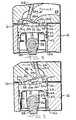
- the cylinder head 12 includes a rigid casting 10a that defines a sealing surface 14 for sealingly engaging a cylinder block 16 (shown in Figures 5 and 6) that defines an internal cylinder wall 16a.
- Apertures 18 extend through the casting and receive fasteners by which the head 10 is clamped to the cylinder 16.
- the cylinder head 10 defines a combustion chamber wall 20 which together with the piston 12 and cylinder block 16 defines a combustion chamber 22.
- the cylinder head 12 slidably mounts conventional poppet-type intake and exhaust valves 24, 26 which control the communication between respective intake and exhaust passages 28, 29 defined by the cylinder head 10, and the combustion chamber 22.
- a threaded bore 30 (shown in Figures 1 and 3) opens into the combustion chamber and serves to mount a mixture ignition device such as a spark plug 32, shown in Figure 1.
- the piston 12 includes a conventional piston skirt 12a and a piston crown 12b constructed in accordance with the invention.
- the piston skirt 12a defines spaced aligned bores 34, formed in spaced apart webs 35 (see Figures 7 and 8) which receive a wrist pin 36 by which a connecting rod 38 is pivotally connected to the piston (shown in Figures 5 and 6).
- Grooves 34a (shown only in Figure 8) are formed at the outer ends of the bores 34 and receive lock rings to secure the wrist pin 36 in position.
- two ramp-like projections 50, 51 are formed on the top of the piston crown 12b.
- Complemental shaped recesses 52, 53 are formed in the combustion chamber wall 20 and are arranged to receive the projections 50, 51, respectively, when the piston 12 is at top-dead-center (TDC).
- the projections 50, 51 define gradually sloping surfaces 50a, 51 a, that extend downwardly from arcuate, leading peripheral edges 56, 57 to substantially horizontal piston crown surfaces 58, 59, respectively, of the piston crown 12b.
- the outer periphery of the projections 50, 51 are preferably defined by contoured edges 60, 62 that conform substantially to the piston circumference.
- the inner periphery of the projections 50, 51 is defined by a common boundary line 63 that merges into contoured boundary lines 63a, 63b, which define the base of the projections 50, 51, respectively.
- the projections 50, 51 are disposed in a close fitting, side-by-side arrangement, symmetrical about the central axis of the piston.
- the lateral extent of the horizontal surfaces 58, 59 gradually tapers from the termination of the respective projections.
- the top of the piston appears to define a pair of interfitting, curved tear-drop shaped surfaces arranged in a "Yin and Yang" relation.
- the peripheral edges 56, 57, 60 and 62 of the two projections are spiral and appear to define an S-shape as viewed in Figure 4.
- the recesses 52, 53 define inclined surfaces that in the illustrated embodiment substantially parallel the sloping surfaces 50a, 51a of the associated piston projections 50, 51.
- valve heads 24a, 26a of the intake and exhaust valves 24, 26, at least partially define the recesses 52, 53, respectively.
- the intake and exhaust valves 24, 26 are canted so that the under surfaces of the valve heads 24, 26 are disposed in planes substantially parallel to the sloping surfaces 50a, 51 a of the associated projections 50, 51, respectively.
- the piston surfaces, recesses and valves are arranged so that regions of low and high pressure are generated in the combustion chamber 22 as the piston approaches top-dead-centre.
- the clearance "C,” defined between the bottom of the valve heads 24a, 26a and the sloping projection surfaces 50a, 51a are selected to be different from the clearance "C 2 " between the top surfaces 58, 59 of the piston 12 and horizontal undersurface portions 20a, of the combustion chamber wall 20.
- regions of high and low pressures 22a, 22b will develop in the combustion chamber 22 between the cylinder head surfaces 20a and the piston top surfaces 58, 59 and between the projections 50, 51 and the valve heads 24a, 26a, respectively.
- This dynamic pressure differential will cause the fuel mixture trapped between the surfaces 20a, 58, 59 (the high pressure regions 22a) to travel towards the regions of lower pressure 22b, i.e., upwardly along the sloping projection surfaces 50a, 51a of the projections 50, 51.
- the actual motion of the fuel mixture along the projections is in the nature of rotation about the piston axis as designated by the arrow 80.
- the concurrent generation of movement along each projection 50, 51 produces an overall rotative movement in the fuel mixture within the cylinder.
- the problem of "charge dilution" is substantially reduced.
- the centrifugal forces generated by the rotating air/ fuel mixture both before and during the reaction tends to concentrate the lighter constituents near the axis of rotation and to drive the heavier components towards the periphery of the cylinder.
- the byproducts or exhaust gases are generally lighter and therefore tend to remain near the center of the piston whereas the heavier air/fuel mixture is driven outwardly towards the cylinder walls.
- the centrifugal forces tend to prevent comingling or dilution of the air/fuel mixture by the reaction byproducts.
- the fuel-to-air ratio remains relatively constant throughout the cylinder during the entire reaction process. The stoichiometric ratio is maintained, even at the cylinder walls, and therefore the reaction does not terminate prematurely.
- Dilution of the fuel air mixture and exhaust byproducts is also inhibited by a circular pressure front that is established during the reaction process due to the rotation of the fuel/air mixture.
- a spiralling wall of flame begins propagating radially from the point of ignition, which is preferably located near the rotational axis defined by the rotating fuel mixture, towards the cylinder wall 16a.
- the wall of flame defines a region of extremely high pressure which separates the unburned fuel mixture located between the flame wall and the cylinder wall 16a from the burned products located inside the flame wall.
- the high pressure prevents the unburned mixture and the products of combustion from crossing the flame front and thus the unreacted and reacted constituents remain separated during the combustion process. It is believed that by preventing the comingling of these constituents, a leaner fuel/air mixture can be reliably reacted without degrading engine performance or operation.
- the spark plug 32 is oriented so that its electrode (not shown) is positioned a spaced distance from an imaginary line connecting the axes of the valves 24, 26. In other words, the spark plug electrode is spaced, or offset, from the center of the cylinder. With the disclosed spark plug positioning, rotation of the mixture during the compression stroke tends to promote cooling and cleaning of the spark plug electrode.
- a uniform clearance "C,” between the bottom of the valve heads 24a, 26a and the projection surfaces 50a, 50b is illustrated.
- the axes of the valves 24, 26 (as defined by valve stems 24b, 26b) define angles of inclination of substantially 15° with respect to the vertical as viewed. It should be apparent, that the angle of inclination of the valves 24, 26 or the slope of the projection top surfaces 50a, 51a can be altered to define a gradually decreasing clearance in the region 22b of the combustion chamber, to further promote movement in the fuel mixture.
- the clearance "C,”, “C 2 " can be selected so that the clearance C 2 (in the region 22a) is greater than the clearance C 1 (in the region 22b) so that reverse rotation of the mixture can be effected.
Landscapes
- Engineering & Computer Science (AREA)
- Chemical & Material Sciences (AREA)
- Combustion & Propulsion (AREA)
- Mechanical Engineering (AREA)
- General Engineering & Computer Science (AREA)
- Combustion Methods Of Internal-Combustion Engines (AREA)
- Valve Device For Special Equipments (AREA)
- Valve-Gear Or Valve Arrangements (AREA)
Claims (8)
Priority Applications (1)
| Application Number | Priority Date | Filing Date | Title |
|---|---|---|---|
| AT83301441T ATE25538T1 (de) | 1982-06-21 | 1983-03-16 | Brennkraftmaschine. |
Applications Claiming Priority (2)
| Application Number | Priority Date | Filing Date | Title |
|---|---|---|---|
| US06/390,525 US4467752A (en) | 1982-06-21 | 1982-06-21 | Internal combustion engine |
| US390525 | 1982-06-21 |
Publications (3)
| Publication Number | Publication Date |
|---|---|
| EP0097409A2 EP0097409A2 (de) | 1984-01-04 |
| EP0097409A3 EP0097409A3 (en) | 1984-05-09 |
| EP0097409B1 true EP0097409B1 (de) | 1987-02-25 |
Family
ID=23542817
Family Applications (1)
| Application Number | Title | Priority Date | Filing Date |
|---|---|---|---|
| EP83301441A Expired EP0097409B1 (de) | 1982-06-21 | 1983-03-16 | Brennkraftmaschine |
Country Status (7)
| Country | Link |
|---|---|
| US (1) | US4467752A (de) |
| EP (1) | EP0097409B1 (de) |
| JP (1) | JPS597728A (de) |
| AT (1) | ATE25538T1 (de) |
| AU (1) | AU1134583A (de) |
| CA (1) | CA1210285A (de) |
| DE (1) | DE3369869D1 (de) |
Families Citing this family (40)
| Publication number | Priority date | Publication date | Assignee | Title |
|---|---|---|---|---|
| GB2153428B (en) * | 1984-01-25 | 1987-10-28 | Ricardo Consulting Eng | Spark ignited i c engine combustion chambers |
| JPS6166728A (ja) * | 1984-09-07 | 1986-04-05 | Japan Styrene Paper Co Ltd | 凹凸状断熱板製造用発泡板 |
| US4681715A (en) * | 1984-11-16 | 1987-07-21 | The Dow Chemical Company | Steam expandable polymeric composition and method |
| JPS61278544A (ja) * | 1985-06-03 | 1986-12-09 | Japan Styrene Paper Co Ltd | P−メチルスチレン系樹脂発泡体 |
| US4982289A (en) * | 1989-05-15 | 1991-01-01 | Matsushita Electric Industrial Co., Ltd. | Liquid cooled cathode ray tube apparatus for video projection system |
| US5390634A (en) * | 1993-08-20 | 1995-02-21 | S & S Cycle, Inc. | Internal combustion engine having high performance combustion chamber |
| CA2132282C (en) * | 1993-10-29 | 2005-11-22 | Richard William Smith, Jr. | High performance head assembly for an internal combustion engine |
| USD373773S (en) | 1995-09-12 | 1996-09-17 | Hund Jr Bernie | Compressed combustion piston |
| US5738057A (en) * | 1995-09-29 | 1998-04-14 | Alto Automotive, Inc. | Low profile internal combustion engine |
| US6170454B1 (en) | 1998-07-31 | 2001-01-09 | Techniphase Industries, Inc. | Piston apparatus and methods |
| US6295961B1 (en) * | 1999-11-12 | 2001-10-02 | Jacob Glen Carter | Internal combustion rotating spherical head and valve |
| US7284524B2 (en) * | 2005-02-25 | 2007-10-23 | Lycoming Engines, A Division Of Avco Corporation | Cylinder head assemblies |
| US20060243227A1 (en) * | 2005-04-28 | 2006-11-02 | Greve Christopher G | Variable-compression engine |
| US8091537B2 (en) * | 2007-11-20 | 2012-01-10 | Kelsey Manning | Apparatus and method for engine head |
| EP2286077A4 (de) * | 2008-04-16 | 2011-10-26 | Exodus R & D Pty Ltd | Verbesserter verbrennungsmotor |
| US8468822B1 (en) | 2010-12-07 | 2013-06-25 | Rix E. Evans | Charge preparation system for internal combustion engines |
| DE102012103212A1 (de) * | 2012-04-13 | 2013-10-17 | Mwm Gmbh | Kolben einer Brennkraftmaschine |
| US9091199B2 (en) * | 2013-02-26 | 2015-07-28 | GM Global Technology Operations LLC | Combustion system for an engine having a swirl inducing combustion chamber |
| US10415456B2 (en) * | 2014-04-29 | 2019-09-17 | Volvo Truck Corporation | Combustion chamber for an internal combustion engine and an internal combustion engine |
| NO338265B1 (no) * | 2014-09-15 | 2016-08-08 | Viking Heat Engines As | Arrangement for og fremgangsmåte ved innløpsventil for eksternvarmemaskin |
| US9822729B2 (en) * | 2015-11-02 | 2017-11-21 | Caterpillar Inc. | Engine piston having a notched top land |
| US10422299B2 (en) * | 2016-04-21 | 2019-09-24 | Tenneco Inc. | Piston with asymmetric upper combustion surface and method of manufacture thereof |
| US9995203B2 (en) | 2016-10-27 | 2018-06-12 | Caterpillar Inc. | Piston design for flow re-direction |
| US10087882B2 (en) | 2016-10-31 | 2018-10-02 | Caterpillar Inc. | Piston design for splitting jets |
| US9869270B1 (en) | 2016-10-31 | 2018-01-16 | Caterpillar Inc. | Piston design for jet placement |
| US10989138B2 (en) | 2017-03-30 | 2021-04-27 | Quest Engines, LLC | Internal combustion engine |
| US11041456B2 (en) | 2017-03-30 | 2021-06-22 | Quest Engines, LLC | Internal combustion engine |
| WO2018183503A1 (en) * | 2017-03-30 | 2018-10-04 | Quest Engines, LLC | Internal combustion engine |
| US10465629B2 (en) | 2017-03-30 | 2019-11-05 | Quest Engines, LLC | Internal combustion engine having piston with deflector channels and complementary cylinder head |
| US10590813B2 (en) | 2017-03-30 | 2020-03-17 | Quest Engines, LLC | Internal combustion engine |
| US10753308B2 (en) | 2017-03-30 | 2020-08-25 | Quest Engines, LLC | Internal combustion engine |
| US10598285B2 (en) | 2017-03-30 | 2020-03-24 | Quest Engines, LLC | Piston sealing system |
| US10590834B2 (en) | 2017-03-30 | 2020-03-17 | Quest Engines, LLC | Internal combustion engine |
| US10526953B2 (en) | 2017-03-30 | 2020-01-07 | Quest Engines, LLC | Internal combustion engine |
| KR102468662B1 (ko) | 2017-04-28 | 2022-11-18 | 퀘스트 엔진스, 엘엘씨 | 가변 체적 챔버 장치 |
| US10883498B2 (en) | 2017-05-04 | 2021-01-05 | Quest Engines, LLC | Variable volume chamber for interaction with a fluid |
| US10808866B2 (en) | 2017-09-29 | 2020-10-20 | Quest Engines, LLC | Apparatus and methods for controlling the movement of matter |
| WO2019147797A2 (en) | 2018-01-26 | 2019-08-01 | Quest Engines, LLC | Audio source waveguide |
| US10753267B2 (en) | 2018-01-26 | 2020-08-25 | Quest Engines, LLC | Method and apparatus for producing stratified streams |
| US10865735B1 (en) * | 2018-03-03 | 2020-12-15 | Steven H. Marquardt | Power piston |
Family Cites Families (37)
| Publication number | Priority date | Publication date | Assignee | Title |
|---|---|---|---|---|
| US1708428A (en) * | 1929-04-09 | Turbulence-producing combustion chamber fob internal-combustion | ||
| US1664782A (en) * | 1925-01-20 | 1928-04-03 | Edward C Magdeburger | Internal-combustion engine |
| US1734763A (en) * | 1926-05-17 | 1929-11-05 | Maxmoor Corp | Internal-combustion engine |
| US1734764A (en) * | 1926-06-03 | 1929-11-05 | Maxmoor Corp | Internal-combustion engine |
| US1708425A (en) * | 1926-10-11 | 1929-04-09 | Maxmoor Corp | Antidetonation combustion chamber for internal-combustion engines |
| US1708426A (en) * | 1926-10-13 | 1929-04-09 | Maxmoor Corp | Antidetonating piston head for internal-combustion engines |
| US1717578A (en) * | 1926-10-18 | 1929-06-18 | Maxmoor Corp | Antidetonation combustion chamber for internal-combustion engines with plural projections |
| US1708427A (en) * | 1926-10-18 | 1929-04-09 | Maxmoor Corp | Antidetonation combustion chamber for internal-combustion engines |
| US1656359A (en) * | 1926-10-30 | 1928-01-17 | Maxmoor Corp | Turbine-vaned antidetonation cylinder head for internal-combustion engines |
| US1678348A (en) * | 1926-10-30 | 1928-07-24 | Maxmoor Corp | Combustion chamber for internal-combustion engines |
| US1856328A (en) * | 1926-11-24 | 1932-05-03 | Louis O French | Internal combustion engine |
| US1754643A (en) * | 1927-01-03 | 1930-04-15 | Moore Arlington | Antidetonation cylinder head for internal-combustion engines |
| US1673775A (en) * | 1927-01-17 | 1928-06-12 | Maxmoor Corp | Antidetonation piston-head formation for internal-combustion engines |
| US1656360A (en) * | 1927-01-17 | 1928-01-17 | Maxmoor Corp | Antidetonation piston construction for internal-combustion engines |
| US1798967A (en) * | 1927-07-18 | 1931-03-31 | Chedru Gustave Emile | Internal-combustion engine |
| US1901448A (en) * | 1929-06-05 | 1933-03-14 | Carl F High | Internal combustion engine |
| FR802762A (fr) * | 1935-03-06 | 1936-09-15 | Moteur à combustion interne à quatre temps comportant une distribution à tiroir | |
| US2346021A (en) * | 1938-11-08 | 1944-04-04 | Atlantic Diesel Corp | Internal combustion engine |
| US2231392A (en) * | 1939-01-26 | 1941-02-11 | John J Mccarthy | Internal combustion engine |
| US2172170A (en) * | 1939-06-17 | 1939-09-05 | Megroot John Peter | Internal combustion engine |
| US2669227A (en) * | 1950-04-15 | 1954-02-16 | Chrysler Corp | Overhead valve engine |
| US2662517A (en) * | 1952-03-01 | 1953-12-15 | Jr Albert G Bodine | Piston for internal-combustion engines having acoustic detonation suppression means |
| US2709992A (en) * | 1952-03-07 | 1955-06-07 | Ferro Machine And Foundry Inc | Piston and combustion chamber construction for compression ignition engine |
| US2766738A (en) * | 1953-07-24 | 1956-10-16 | Daimler Benz Ag | Internal combustion engine |
| US2827033A (en) * | 1954-09-30 | 1958-03-18 | Jr Albert G Bodine | Acoustic wave controlling means for suppressing detonation in internal combustion engines |
| FR1131285A (fr) * | 1955-09-16 | 1957-02-19 | Citroen Sa Andre | Moteur à combustion interne |
| FR1373853A (fr) * | 1963-08-22 | 1964-10-02 | Piston pour moteurs à combustion interne | |
| US3766900A (en) * | 1971-06-22 | 1973-10-23 | G Aiti | Combustion chamber for interval combustion engines |
| CA979811A (en) * | 1972-03-20 | 1975-12-16 | Michael G. May | Two-stroke internal combustion engine and method of scavenging same |
| IT1031159B (it) * | 1974-01-30 | 1979-04-30 | May M G | Morore a combustione interna a ciclo a quattro tempi ad a ccensione esterna |
| US4094272A (en) * | 1975-01-24 | 1978-06-13 | May Michael G | Externally ignited four cycle internal combustion engine |
| US4121544A (en) * | 1975-01-24 | 1978-10-24 | May Michael G | Internal combustion engine |
| US4125105A (en) * | 1975-11-10 | 1978-11-14 | May Michael G | Four cycle internal combustion engine |
| JPS5949407B2 (ja) * | 1976-11-15 | 1984-12-03 | トヨタ自動車株式会社 | 内燃機関の燃焼室 |
| US4162661A (en) * | 1977-02-25 | 1979-07-31 | Toyota Jidosha Kogyo Kabushiki Kaisha | Internal combustion engine with combustion chambers which create a squish and swirl of an air-fuel mixture |
| DE2728903A1 (de) * | 1977-06-27 | 1979-01-18 | August Paul Dr H C | Verfahren zur verbesserung der gemischbildung und beschleunigung der verbrennung des gemisches bei brennkraftmaschinen und brennkraftmaschine zur durchfuehrung des verfahrens |
| US4357915A (en) * | 1980-11-12 | 1982-11-09 | Monsour James R | Propeller and piston combination for internal combustion engines |
-
1982
- 1982-06-21 US US06/390,525 patent/US4467752A/en not_active Expired - Fee Related
-
1983
- 1983-02-11 AU AU11345/83A patent/AU1134583A/en not_active Abandoned
- 1983-03-09 CA CA000423200A patent/CA1210285A/en not_active Expired
- 1983-03-16 EP EP83301441A patent/EP0097409B1/de not_active Expired
- 1983-03-16 DE DE8383301441T patent/DE3369869D1/de not_active Expired
- 1983-03-16 AT AT83301441T patent/ATE25538T1/de not_active IP Right Cessation
- 1983-03-28 JP JP58050592A patent/JPS597728A/ja active Pending
Also Published As
| Publication number | Publication date |
|---|---|
| ATE25538T1 (de) | 1987-03-15 |
| AU1134583A (en) | 1984-01-05 |
| EP0097409A3 (en) | 1984-05-09 |
| CA1210285A (en) | 1986-08-26 |
| DE3369869D1 (en) | 1987-04-02 |
| JPS597728A (ja) | 1984-01-14 |
| US4467752A (en) | 1984-08-28 |
| EP0097409A2 (de) | 1984-01-04 |
Similar Documents
| Publication | Publication Date | Title |
|---|---|---|
| EP0097409B1 (de) | Brennkraftmaschine | |
| US4324214A (en) | Combustion chamber for an internal combustion engine | |
| US4669431A (en) | Internal combustion engine with dual combustion chambers | |
| US4207843A (en) | Compression ignition direct injection internal combustion engine | |
| KR960003018B1 (ko) | 엔진의 흡기장치 및 그 제어방법 | |
| US5320075A (en) | Internal combustion engine with dual ignition for a lean burn | |
| JP2597657B2 (ja) | 内燃機関の燃焼室 | |
| JPS61169612A (ja) | 内燃機関 | |
| US6910455B2 (en) | Spark ignition engine with shallow bowl-in-piston geometry | |
| JPH11343851A (ja) | 内燃機関の燃焼室構造 | |
| US3416501A (en) | Internal-combustion engines | |
| EP0801216B1 (de) | Brennraum einer Brennkraftmaschine | |
| US4508073A (en) | Combustion space of a piston driven internal combustion engine | |
| US4586465A (en) | Internal combustion engine | |
| JP2002525473A (ja) | エンジンの転換 | |
| EP0299747B1 (de) | Brennkraftmaschine mit Verbrennung eines armen Gemisches | |
| US4267806A (en) | High compression type internal combustion engine | |
| JPS5838610B2 (ja) | 内燃機関 | |
| US6394056B1 (en) | Internal combustion engine | |
| US11512663B2 (en) | Engine with combustion chamber | |
| US4622929A (en) | Deflector piston two-stroke engine | |
| EP0150989A2 (de) | Brennkraftmaschine mit Fremdzündung | |
| US5479888A (en) | Divided chamber type diesel engine | |
| JPH05106452A (ja) | エンジンの吸気装置及び吸気供給方法 | |
| EP0085258A1 (de) | Brennraumanordnungen für Brennkraftmaschinen |
Legal Events
| Date | Code | Title | Description |
|---|---|---|---|
| PUAI | Public reference made under article 153(3) epc to a published international application that has entered the european phase |
Free format text: ORIGINAL CODE: 0009012 |
|
| AK | Designated contracting states |
Designated state(s): AT BE CH DE FR GB IT LI LU NL SE |
|
| PUAL | Search report despatched |
Free format text: ORIGINAL CODE: 0009013 |
|
| AK | Designated contracting states |
Designated state(s): AT BE CH DE FR GB IT LI LU NL SE |
|
| RAP1 | Party data changed (applicant data changed or rights of an application transferred) |
Owner name: MOTORTECH, INC. |
|
| 17P | Request for examination filed |
Effective date: 19841020 |
|
| GRAA | (expected) grant |
Free format text: ORIGINAL CODE: 0009210 |
|
| AK | Designated contracting states |
Kind code of ref document: B1 Designated state(s): AT BE CH DE FR GB IT LI LU NL SE |
|
| REF | Corresponds to: |
Ref document number: 25538 Country of ref document: AT Date of ref document: 19870315 Kind code of ref document: T |
|
| PGFP | Annual fee paid to national office [announced via postgrant information from national office to epo] |
Ref country code: AT Payment date: 19870330 Year of fee payment: 5 |
|
| PG25 | Lapsed in a contracting state [announced via postgrant information from national office to epo] |
Ref country code: LU Free format text: LAPSE BECAUSE OF NON-PAYMENT OF DUE FEES Effective date: 19870331 |
|
| PGFP | Annual fee paid to national office [announced via postgrant information from national office to epo] |
Ref country code: NL Payment date: 19870331 Year of fee payment: 5 |
|
| REF | Corresponds to: |
Ref document number: 3369869 Country of ref document: DE Date of ref document: 19870402 |
|
| ITF | It: translation for a ep patent filed | ||
| ET | Fr: translation filed | ||
| PLBE | No opposition filed within time limit |
Free format text: ORIGINAL CODE: 0009261 |
|
| STAA | Information on the status of an ep patent application or granted ep patent |
Free format text: STATUS: NO OPPOSITION FILED WITHIN TIME LIMIT |
|
| 26N | No opposition filed | ||
| PG25 | Lapsed in a contracting state [announced via postgrant information from national office to epo] |
Ref country code: AT Effective date: 19880316 |
|
| PG25 | Lapsed in a contracting state [announced via postgrant information from national office to epo] |
Ref country code: SE Effective date: 19880317 |
|
| PG25 | Lapsed in a contracting state [announced via postgrant information from national office to epo] |
Ref country code: LI Effective date: 19880331 Ref country code: CH Effective date: 19880331 |
|
| BERE | Be: lapsed |
Owner name: MOTORTECH INC. Effective date: 19880331 |
|
| PG25 | Lapsed in a contracting state [announced via postgrant information from national office to epo] |
Ref country code: NL Effective date: 19881001 |
|
| NLV4 | Nl: lapsed or anulled due to non-payment of the annual fee | ||
| PG25 | Lapsed in a contracting state [announced via postgrant information from national office to epo] |
Ref country code: GB Free format text: LAPSE BECAUSE OF NON-PAYMENT OF DUE FEES Effective date: 19881122 |
|
| GBPC | Gb: european patent ceased through non-payment of renewal fee | ||
| PG25 | Lapsed in a contracting state [announced via postgrant information from national office to epo] |
Ref country code: FR Free format text: LAPSE BECAUSE OF NON-PAYMENT OF DUE FEES Effective date: 19881130 |
|
| REG | Reference to a national code |
Ref country code: CH Ref legal event code: PL |
|
| PG25 | Lapsed in a contracting state [announced via postgrant information from national office to epo] |
Ref country code: DE Effective date: 19881201 |
|
| REG | Reference to a national code |
Ref country code: FR Ref legal event code: ST |
|
| PG25 | Lapsed in a contracting state [announced via postgrant information from national office to epo] |
Ref country code: BE Effective date: 19890331 |
|
| EUG | Se: european patent has lapsed |
Ref document number: 83301441.8 Effective date: 19881206 |