EP0098673A2 - Vorrichtung zum Festmachen eines Tieres - Google Patents
Vorrichtung zum Festmachen eines Tieres Download PDFInfo
- Publication number
- EP0098673A2 EP0098673A2 EP83201017A EP83201017A EP0098673A2 EP 0098673 A2 EP0098673 A2 EP 0098673A2 EP 83201017 A EP83201017 A EP 83201017A EP 83201017 A EP83201017 A EP 83201017A EP 0098673 A2 EP0098673 A2 EP 0098673A2
- Authority
- EP
- European Patent Office
- Prior art keywords
- yoke
- axis
- plane
- articulation
- parts
- Prior art date
- Legal status (The legal status is an assumption and is not a legal conclusion. Google has not performed a legal analysis and makes no representation as to the accuracy of the status listed.)
- Withdrawn
Links
- 241001465754 Metazoa Species 0.000 title claims abstract description 39
- 239000000725 suspension Substances 0.000 claims description 18
- 239000002184 metal Substances 0.000 claims description 5
- 229910052751 metal Inorganic materials 0.000 claims description 5
- 210000003813 thumb Anatomy 0.000 claims description 5
- 238000006073 displacement reaction Methods 0.000 description 4
- 241000283690 Bos taurus Species 0.000 description 2
- 229940082150 encore Drugs 0.000 description 2
- 230000007935 neutral effect Effects 0.000 description 2
- 229910000746 Structural steel Inorganic materials 0.000 description 1
- 230000006978 adaptation Effects 0.000 description 1
- 239000000872 buffer Substances 0.000 description 1
- 239000000470 constituent Substances 0.000 description 1
- 230000000694 effects Effects 0.000 description 1
- 230000005484 gravity Effects 0.000 description 1
- 235000000396 iron Nutrition 0.000 description 1
- 230000009347 mechanical transmission Effects 0.000 description 1
- 239000000203 mixture Substances 0.000 description 1
- 230000004048 modification Effects 0.000 description 1
- 238000012986 modification Methods 0.000 description 1
- 230000000717 retained effect Effects 0.000 description 1
- 230000000630 rising effect Effects 0.000 description 1
Images


Classifications
-
- A—HUMAN NECESSITIES
- A01—AGRICULTURE; FORESTRY; ANIMAL HUSBANDRY; HUNTING; TRAPPING; FISHING
- A01K—ANIMAL HUSBANDRY; AVICULTURE; APICULTURE; PISCICULTURE; FISHING; REARING OR BREEDING ANIMALS, NOT OTHERWISE PROVIDED FOR; NEW BREEDS OF ANIMALS
- A01K1/00—Housing animals; Equipment therefor
- A01K1/06—Devices for fastening animals, e.g. halters, toggles, neck-bars or chain fastenings
- A01K1/062—Neck-bars, e.g. neck collars
Definitions
- Devices of this kind are in particular intended for tying cows.
- the suspension element consists of an assembly which extends clearly beyond above the upper articulation axes of the upper parts of the yoke branches, and the space between the upper parts does not remain free at the top over an appreciable height, for the animal attached.
- the object of the invention is to eliminate this drawback and to offer a compact, reliable and simple structure which, in the closed position of the yoke, leaves practically all of the headroom for the bound animal.
- the upper parts are connected in an articulated manner to each other at the top, with an axis of articulation perpendicular to the main straightening plane.
- a device for attaching an animal the upper parts of the yoke branches of which are articulated to each other at the top, with an articulation axis perpendicular to the main yoke plane, is known per se from DE-AS-1,218,789.
- the invention offers, on the contrary, a device the upper parts of the yoke branches of which are hingedly connected to each other above and which can however still be provided with the necessary means which allow the device to be closed by the animal itself.
- the closing of the yoke is caused by the animal arriving without displacement of the yoke towards the feeder or with a minimum displacement in this direction, because the animal exerts a push down on the lower parts of the branches of yoke.
- This embodiment of the invention therefore allows closure by the animal because the latter exerts a downward push on parts of the device, while the closure of the device according to Belgian patent n ° 885.292 is caused by the fact let the animal push the shackles forward, in the direction of the feeder.
- the closing of the yoke is caused by the animal arriving without or with a slight push towards the front of the yoke, because the animal acts on a control member.
- the device comprises a control member which is connected by a mechanical connection to the upper parts and is articulated around an axis parallel to the yoke plane, between a first position in which it maintains the upper parts mutually spaced apart, via this mechanical connection, and it partially closes the space between the upper parts, and a second position in which it maintains the upper parts in a mutually parallel position, via this mechanical connection.
- a device for attaching an animal with a control member acting by means of a mechanical connection on the upper parts of the branches of a yoke and which, in the position where it keeps these upper parts mutually apart, partially closes the space between the upper parts, is known per se from DE-A-28 45 521.
- This known device however has the disadvantage in particular that its suspension still requires a fairly great height above the upper ends of the shackles, which is eliminated according to the invention, inter alia, because the upper parts are hinged together at the top with an axis of articulation which is perpendicular to the plane of main yoke, of so that the suspension can take place either by means of this articulation axis, or directly by means of the upper parts of the shackles.
- the means which, in an extreme position, hold the upper parts of the yoke branches in the closed position and, in the other extreme position, keep them in a separated position are constituted by a tension spring which is located in an extreme position below the articulation axes and, in the other extreme position, above these articulation axes.
- the spacing between the shackles is made adjustable, so that the device can be used for smaller and larger animals, the tensile force exerted by the spring varies according to the chosen setting, which consists in known devices, to move the axes of articulation of the upper parts of the yoke branches relative to the suspension element.
- the device according to the invention allows different adjustments of the upper parts of the shackles which take account of the width of the animal to be attached, while still allowing the same tensile force to be exerted with one and the same spring. both in the open position and in the closed position of the yoke.
- the upper parts are hingedly connected to each other at the top by a hinge pin which is fixed relative to a support plate which is adjustably mounted relative to one of the upper parts, provided with several openings for the articulation axis, and the means which, in one extreme position, hold the upper parts in their closed position and, in the other extreme position, keep them in their separated position, comprise a tension spring one end of which is connected to the support plate and the other end to the other upper part, tension spring whose center line in an extreme position of the upper parts, is located above the axis of articulation and, in the Another extreme position of the upper parts, below this axis of articulation.
- the angle which is formed by the upper parts when they take their apart position, is independent of the adjustment which takes into account the width of the animal to be attached, when the support plate and the other upper part each have a stop, these stops meeting in the open position of the yoke.
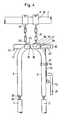
- the device represented in FIGS. 1 to 11 for attaching an animal is mounted inside a fixed structure to which the floor 1 and the upper beam 2 belong.
- This device is intended to tie a cow in a lying-and-standing station.
- the transverse direction of the latter corresponds to the direction of the beam 2.
- the longitudinal direction is perpendicular to it. This is the direction that the animal follows when it normally enters the lying-and-standing station.
- the device consists essentially of a yoke which is itself constituted by a low yoke 3 and branches of yoke connecting to it.
- Each yoke branch comprises an upper part 8 and 9, and a lower part 6-22-4 and 7-23-5. These parts are hingedly connected to each other, as well as to the suspension chains 34 and at the bottom yoke 3, as described in more detail below.
- the main straightening plane At rest, these parts are in the same plane, called the main straightening plane. Whether the device is in the open or closed state, as described below, in equilibrium the whole device is in any case placed with the main plane of yoke in a direction which corresponds to the transverse direction of the lying station -and-standing.
- this station On one side of the device extending at rest in the transverse direction of the lying-and-standing station, said below front side, this station has a feeder.
- the other side of the device is therefore called the rear side.
- the upper parts 8 and 9 each have an eyelet 28 and 29 at the top.
- the eyelets 28 and 29 are perpendicular to the main yoke plane.
- the eyelets 28 and 29 diverge from bottom to top, as can be seen mainly from FIG. 3.
- the transverse beam 2 For the suspension of the yoke, on the transverse beam 2 are located two small fixing brackets 30 which are held on this beam by bolts 31 with nuts 32.
- the fixing brackets 30 carry hooks 33 below which are suspended the chains 34 which are in turn connected to the eyelets 28 and 29. Since the chains 34 are flexible suspension elements, they seek under the influence of their own weight and the yoke hanging from them, the position in which their center lines are parallel to each other. At rest, these center lines define a vertical plane which extends parallel to the upper beam 2, that is to say in the transverse direction of the lying-and-standing station.
- the upper parts 8 and 9 of the yoke will be in a vertical transverse plane, therefore parallel to the upper beam 2, when the chains extend in such a plane. Under the influence of the animal, the yoke and therefore the yoke parts 8 and 9 can be brought out of the transverse plane, but as soon as the force of gravity can act freely, the yoke will return in the transverse plane.
- the bottom yoke 3 is constituted by two branches 11 and 13 which are each integral with a base part 10 and 12.
- the latter are angle irons which engage above by their horizontal portions and below by their vertical portions .
- an opening is made in the horizontal portion and the vertical portion of the base portion 12.
- Bolts 17 and 18 can therefore connect the base parts 10 and 12 to one another in different mutual positions, so that the spacing between the legs 11 and 13 of the bottom yoke is adjustable.
- an eyelet 14 which is connected by a chain 15 to an eyelet 16 which is embedded in the floor 1.
- the device is therefore mounted between the upper beam 2 and the floor 1, via chains 15 and 34.
- the chain 15 hangs loosely, which makes movement of the animal is possible within certain limits. If one wishes to limit this possibility of movement, one can connect to the top of the links chains 34 which are not adjacent, directly between them, for example with a simple hook, which reduces the play in the suspension.
- the upper parts 8 and 9 are interconnected by a pin 35 which forms a hinge axis and is perpendicular to the main yoke plane.
- the upper parts 8 and 9 of the yoke branches carry eyelets 26 located in the main yoke plane.
- eyelets 26 engage the eyelets 25 of the upper ends of the middle parts 6 and 7.
- These eyelets are perpendicular to the main yoke plane and therefore parallel to the plane of vertical longitudinal symmetry of the lying-and-standing station.
- Lower parts 4 and 5 are located between the middle parts 6 and 7 and the branches 11 and 13 of the bottom yoke 3.
- Each lower part 4.5 is articulated, on the one hand, on a middle part 6,7 and, d on the other hand, on a branch 11, 13 of the bottom yoke 3, by means of articulations which allow only a simple hinge movement.
- a second articulation which forms the connection between the lower part 4,5 and the shackles 11,13 has its axis of articulation in the main shackle plane.
- This second articulation has, as articulation pin, a bolt 20 which is supported in the two branches directed towards the top of the part 19 of U-shaped cross section which is welded on the upper end of a branch 11,13 of the bottom yoke 3.
- the bolt passes through an opening which is made for this purpose in the lower part 4.5.
- On the outside of the U-shaped pieces 19 are located on one side the head of the bolt 20 and on the other side a nut 21.
- the branches 11 and 13 of the bottom yoke 3, the middle parts 6 and 7 and the upper parts 8 and 9 of the main shackles are round tubes.
- the lower parts 4 and 5 of the main shackles are bars of rectangular cross section.
- Each middle part 6,7 is connected to an upper part 8,9 by the aforementioned first articulation 25-26 and to a lower part 4,5 by a third articulation.
- the axis of the third joint is perpendicular to the main yoke plane.
- Each third articulation has, as articulation pin, a bolt 24 which is supported in a stop 22,23 which is integral with a middle part 6,7.
- the pin 24 passes through an opening which is made at the top in the lower part 4.5. In the closed state of the yoke, the stops 22 and 23 enclose the lower parts 4.5.
- the animal tied in the yoke can then push the middle parts 6 and 7 forward and thus cause a pivoting movement of the middle parts 6, 7 together with the low parts 4.5 around the hinge pins 20, but for the attached animal, a pivoting movement at the height of the articulation pins 24 is practically excluded even in the direction perpendicular to the main yoke plane, even if there should be some play in the articulations with the pins 24 .
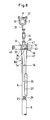
- the upper parts 8 and 9 have at the top curved portions facing each other.
- the curved portion of the upper part 8 is much longer than that of the upper part 9, but the curved portion of this upper part 9 is extended by two flanges 36 and 37 between which is housed the curved portion of the upper part 8
- In the curved portion of the upper part 8 is made an opening for the pin 35 which forms the axis of articulation of the upper part R with respect to the upper part 9.
- the flanges 36 and 37 are made opposite the from each other, three similar openings 62, so that the pin 35 can hinge together the upper parts 8 and 9 in three different positions.
- a fourth opening 63 was also made in the flange 37 on the side opposite to the upper part 8, beyond the three openings 62.
- a support plate illustrated separately in FIGS. 10 and 11, has two pins rising there perpendicularly, namely the pin 35 forming the articulation axis of the upper parts 8 and 9, and a second pin 42.
- the spacing between the center lines of pins 35 and 42 is equal to the spacing between adjacent openings 62 and 63.
- the second pin 42 is significantly shorter than the pin 35 and it is also significantly thinner.
- the pin 35 forming the articulation axis between the upper parts 8 and 9 must in fact penetrate from the support plate 41 through the flange 37 and the upper part 8 in the flange 36, while the pin 42 penetrates simply from the support plate 41 in an opening 62 or 63 formed in the flange 37.
- the pin 35 in fact still projects out of the flange 36 and is retained there by a split pin 38.
- the support plate 41 has a plate 43 in which an opening 46 is made for fixing the end of a tension spring 44. On its upper edge, the plate support 41 has a stop 45.
- a part 47 with a horizontal part and a vertical part On the upper part 8, therefore that relative to which the support plate 41 is not mounted, is welded a part 47 with a horizontal part and a vertical part.
- the part 47 carries a plate 48 in which an opening 49 is made for fixing the other end of the spring 44.
- the tension spring 44 therefore pulls on the one hand on the part 47 which is integral with the upper part 8 and , on the other hand, on the support plate 41 which is mounted relative to the upper part 9.
- the spring 44 in the closed state of the yoke, the spring 44 is located completely in below the articulation axis 35 of the upper parts 8 and 9.
- the spring 44 In the separated state of the yoke, the spring 44 is situated completely above the articulation axis 35 upper parts 8 and 9.
- the spring 44 When the center line of the spring 44 passes through the center line of the hinge pin 35, the spring is in neutral where it pulls the upper parts 8 and 9 neither towards the closed position, nor towards that of 'spacing. In an upper position of the spring 44 relative to the hinge pin 35, it pulls the upper parts 8 and 9 towards their spacing position. In a lower position of the spring 44 relative to the hinge pin 35, it pulls the upper parts 8 and 9 towards their closed position.
- a stop 50 On the part 47 which is itself fixed relative to the upper part 8, is welded a stop 50. The latter meets the stop 45 when the yoke is in the spacing position, as is clear in particular from Figure 7.
- the stops 45 and 50 therefore define the extreme opening position of the yoke.
- the shackles have been shown, both for the closed state and for the open state, in the position they assume for the smallest animals.
- the pin 35 is then located in the openings 62 of the flanges 36 and 37 which are closest to the upper part 9.
- the second pin 42 is then located in the opening 63. Since the cross section of the second pin 42 is less than that of the opening 63, the spring 44 pulls in the closed position of the yoke, the support piece 41 somewhat downward relative to the flanges 36 and 37, so that the spring 44 comes to lie still a little further below its neutral point than would be the case if the support piece 41 was exactly in line with the flanges 36 and 37. This contributes to keeping the upper parts 8 and 9 more firmly in their closed state.
- the hinge pin or first pin 35 is not in the openings 62 closest to the upper part 9, but in one of the other pairs openings 62.
- the second pin 42 is then in an opening 62 of the flange 37, but this does not change anything in the operation described above.
- the support plate 41 remains always mounted in the same way relative to the upper part 8, so that for opening and closing of the yoke the spring 44 always exerts the same force and the stops 45 and 50 always define the position apart from the upper parts 8 and 9 in the same way.
- the lock has as main body a curved slat 54 which extends next to the upper part 8 and is articulated relative to the latter around a bolt 56 which extends along the main yoke plane.
- the bolt 56 passes through the upper part 8, meets the latter by its head on one side and carries at its other end a nut 57 which holds the slat 54 against the upper part 8.
- the slat 54 is somewhat curved inwards at the top, as far as behind the vertical part of the part 47. In this place the slat 54 carries a projection 51 which passes through a slot 61 made in the vertical part of the part 47. On on the front side, a split pin 52 passes through the projection 51, which prevents the latter from being pulled out of the slot 61 towards the rear of the vertical part of the part 47. On the rear face of the part 47, around the projection 51, is a spring 53 which pushes the upper part of the main body 54 of the lock backwards. Below, the main body 54 of the lock carries a thumb rest 55. The latter is located in the vicinity of the handle 27 which is welded to the upper part 8.
- the yoke can be opened in two different ways, namely by hand and by means of the control member illustrated in FIGS. 12 to 14.
- the handle 27 For opening by hand, the handle 27 is firmly grasped and pressure is applied to the thumb rest 55 against the action of the spring 53. As a result, the main body 54 undergoes a movement of limited pivoting in the direction of arrow 106 in FIG. 8. The main body 54 of the bolt is then withdrawn from beneath the flange 36, so that one can then exert a pull by hand on the handle 27 and consequently on the upper part 8, which separates the latter from the upper part 9 and therefore finally brings the yoke to the open position. The upper part 8 can be moved away from the upper part 9 around the hinge pin 35 until the stops 45 and 50 meet. As soon as during this movement, the spring 44 has passed over the hinge pin 35, it contributes to effecting and maintaining the opening of the yoke.
- the latter which however is not controlled directly by hand, is fixed to the flange 36 by means of a separator 39.
- the control member according to FIGS. 12 to 14 is constituted by a bent handle 58 which carries on one side a funnel 59. On the outer face of the latter is a plate 60.
- the operation of the device is as follows.
- the animal which enters the lying-and-standing station goes towards the food in the manger and meets between the latter and itself, the open yoke which extends in the transverse direction of the lying-and-station standing, in the open state illustrated in FIGS. 5 to 7.
- the animal which wants to reach the food passes its head through the opening between the middle parts 6 and 7 and thus pushes on the buffers 22 and 23, which away from each other and therefore brings the portions 6 and 7 above the hinge pins 24.
- the upper parts 8 and 9 also come together, which brings the spring at a given moment. 44 below the hinge pin 35, so that this spring 44 can itself cause the closure to continue.
- the support plate 41 When the parts 8 and 9 have reached the closed position, the support plate 41 will move a little further down to reach the position according to Figure 3, because of the play of the second pin 42 in its opening. As previously indicated, the main body 54 of the lock then passes below the flange 36, which locks the device in the closed state. To open the yoke, the operations described above are carried out, either by acting by hand on the thumb rest 55 and the handle 27 and by moving the upper part 8 away from the upper part 9, or by causing the using the control member according to FIGS. 12 to 14, unlocking and pulling the upper part 9 from the upper part 8.
- the lock acts on the flange 36 at a great distance from the axis 35, which promotes locking.
- the bottom yoke 3 is lacking and the lower parts constituted by the middle parts 6 and 7.1st stops 22 and 23 extending them and the lower parts 4 and 5 are replaced by simple lower parts 64 and 65.
- the lower parts 64 and 65 have above them eyelets 25 which engage in the eyelets 26 which are welded to the lower ends of the upper parts 8 and 9.
- the lower parts 64 and 65 are constituted by tubes whose ends lower are bent towards each other.
- the curved portion of the lower part 64 is much shorter than the curved portion of the lower part 65, but on the curved part of the lower part 64 are welded two flanges 66 between which is housed the curved part of the lower part 65.
- each of the flanges 66 are made three openings 68.
- the latter are located opposite one another in the two flanges 66.
- In the curved part of the lower part 65 is made an opening.
- the latter can be brought in front of a pair of openings in the flanges 66, so that a bolt 67 can then be threaded into the openings facing the flanges 66 and the opening of the lower part 65.
- the bolt meets with its head there the outer face of a flange 66 and bears against the outer face of the other flange 66, a nut.
- the bolt 67 therefore forms a hinge pin for the lower parts 64 and 65, which are adjustable between them, since three pairs of openings are made in the flanges 66. This makes it possible to adjust the spacing between the straight portions lower parts 64 and 65 in the closed state of the yoke.
- One of the flanges 66 carries at the bottom an eyelet 14 which is connected, via the chain 15, to an eyelet 16 embedded in the ground.
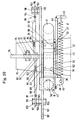
- the pin 35 which forms the axis of mutual articulation of the upper parts 8 and 9 and which is fixed on the support plate 41, protrudes in the embodiment according to Figures 15 to 20 much further beyond the flange 36 that this is not the case in the embodiment according to FIGS. 1 to 11.
- On this projecting part of the pin 35 can slide back and forth a small socket 76.
- the latter carries a plate 75 which s 'extends in a vertical plane perpendicular to the yoke plane.
- This plate 75 is engaged by a parallel plate 74. It therefore also extends in a vertical plane perpendicular to the yoke plane and in fact following the plane of symmetry of the device which is perpendicular to the yoke plane.
- the plates 74 and 75 are made openings for a bolt 77 which forms an axis of articulation for the plate 74 relative to the plate 75.
- the bolt 77 engages by its head the plate 74 and carries a nut against the plate 75
- the plate 74 is secured to a curved metal plate 70 which belongs to a stopper 69 which controls the closing and opening of the yoke.
- This stopper consists of the aforementioned curved metal plate 70 and a piece of rubber 71 which is fixed to the plate by means of bolts 72 and nuts 73.
- the part 71 is located at the bottom and in this open position the stopper 69 closes the opening between the yoke arms, especially between the upper parts thereof.
- the metal plate 70 of the stopper 69 is connected by a mechanical connection which will be described in more detail below, to each of the upper parts 8 and 9 of the shackles.
- the stopper 69 therefore forms a control member for the shackles.
- the metal plate 70 carries a second plate 79 perpendicular to the plate 74.
- the flat portions 82 and 83 which form the ends of rods 84 and 85 whose ends opposite to the flat portions 82 and 83, have a thread.
- the plate 79 and the flat parts 82 and 83 are connected in an articulated manner by a bolt 80 which forms a hinge pin.
- the bolt engages with its head the flat portion 82 of the rod 84 and is held in position by a nut 81 which engages the surface opposite to the flat portions 82 and 83, of the plate 79.
- the threaded part of the rod 84 is screwed into a nut 86 which is secured to a small tube 88 which in turn is secured to a blade 92 of a joint 90 with a hinge pin 94.
- the second blade 96 of this hinge 90 is located around a pin 98 which is fixed on a flange 100 which is in turn welded to the part 47 which is integral with the upper part 8 d 'a straitjacket branch.
- the blade 96 of the joint 90 is held in place around the pin 98 between nuts 102.
- the threaded portion of the rod 85 is screwed into a nut 87 which is integral with a small tube 89 which in turn is integral with a blade 93 of a joint 91 with an articulation axis 95.
- the second blade 97 of this joint 91 is around a bolt 99 which is itself mounted in one of the openings 101 made for this purpose in the flange 36 which, as described above, is integral with the upper part 9 of a straitjacket branch.
- the blade 97 of the hinge 91 is held in place around the bolt 99 forming a hinge pin between nuts 103.
- One of these latter keeps out: turn the bolt 99 fixed in an opening 101 on the flange 36 qu also engages the head 104 of the bolt 99.
- the stopper or control member 69 is articulated around the axis formed by the bolt 77 which always remains parallel to the yoke plane, between a first low position illustrated in FIGS. 18 and 19, in which it maintains the upper parts 8 and 9 separated from one another and partially closes the space between the upper parts 8 and 9, and a second high position illustrated in FIGS. 15 to 17, in which it maintains the upper parts 8 and 9 in the mutually parallel position , therefore in the closed yoke position.
- the bolt 77 which is parallel to the yoke plane and relative to which the control member is articulated, is fixed in the plate 75 which is itself integral with the small bush 76 which can slide alternately on the pin 35 which forms the axis of articulation of the upper parts 8 and 9.
- the plate 75 which is itself integral with the small bush 76 which can slide alternately on the pin 35 which forms the axis of articulation of the upper parts 8 and 9.
- the flanges 36 and 37 which are integral with the upper part 9.
- In the aforementioned flange 100 integral with the upper part 8 is also made an opening for the passage of the pin 35.
- the plate 70 of the control member 69 is connected, on the one hand, to the pin 98 of the flange 100 secured to the upper part 8 and, on the other hand, to the bolt 99 mounted in the flange 36 secured to the upper part 9.
- the mechanical connection described above therefore connects the control member 69 to the flanges 100 and 36 which extend the upper parts 8 and 9 beyond their axis of mutual articulation 35.
- These flanges 100 and 36 form extensions of the upper parts 8 and 9 which, in the closed state of the yoke, extend beyond the other upper part 9 and 8, which mainly results from the Figures 16 and 20.
- the rod 85 and the small tube 89 can in fact be considered as a single rod made up of two elements 85 and 89 located in the extension of one another and which can be made to rotate with respect to each other around their common geometric axis. It is in fact the same for the rod 84 and the small tube 88.
- One of these elements 84 or 85 respectively, is then articulated around a bolt forming an axis 80, which is fixed relative to the member 69 and lies in a plane perpendicular to the yoke plane and containing the axis of mutual articulation of the upper parts 8 and 9.
- a projection 107 of the main body 54 of the latch reaches below a projection 105 of the plate 70 of the control member 69.
- a small cylinder 108 Around the projection 105 is located a small cylinder 108. If the animal had to try, in the closed position, to spread the branches 8 and 64, on the one hand, and 9 and 65, on the other hand, this would be accompanied by a downward movement of the control member 69, which is prevented because the latch with the projection 107 of the main body 54 is in the path of the downward movement of the projection 105 of the plate 70.
- flange 36 In the flange 36 are made several openings 101 in order to be able to adapt the mechanical transmission, by displacement of the bolt 99 from one opening 101 to another, to the adaptation in width of the yoke which takes place by moving the pin 35 of a opening 62 to another, as described above with regard to the embodiment according to FIGS. 1 to 11.
- the cotter pin 38 can be eliminated in the embodiment according to the figures 15 to 20.
- the opening of the yoke is effected by pulling down the control member 69, the part of the main body 54 of the lock below the bolt 56 forming a pin d joint may disappear, likewise the handle 27 on the upper part 8 may fail and the thumb rest 55 can also be eliminated. It is in fact the same for the handle 40 and the control member 58-59-60.
- the chains do not necessarily have to be connected directly to the separate upper parts of the shackles.
- One or two chains can also carry a small stirrup in which the axis of articulation of one of the upper parts relative to the other is suspended.
Landscapes
- Life Sciences & Earth Sciences (AREA)
- Zoology (AREA)
- Environmental Sciences (AREA)
- Animal Husbandry (AREA)
- Biodiversity & Conservation Biology (AREA)
- Toys (AREA)
- Clamps And Clips (AREA)
Applications Claiming Priority (2)
| Application Number | Priority Date | Filing Date | Title |
|---|---|---|---|
| BE2/59771A BE893805R (en) | 1982-04-28 | 1982-07-09 | Suspended animal-tethering equipment - has locking device actuated by component moving stirrup parts together and apart |
| BE2059771 | 1982-07-09 |
Publications (2)
| Publication Number | Publication Date |
|---|---|
| EP0098673A2 true EP0098673A2 (de) | 1984-01-18 |
| EP0098673A3 EP0098673A3 (de) | 1984-02-22 |
Family
ID=3865606
Family Applications (1)
| Application Number | Title | Priority Date | Filing Date |
|---|---|---|---|
| EP83201017A Withdrawn EP0098673A3 (de) | 1982-07-09 | 1983-07-07 | Vorrichtung zum Festmachen eines Tieres |
Country Status (2)
| Country | Link |
|---|---|
| EP (1) | EP0098673A3 (de) |
| DK (1) | DK314083A (de) |
Family Cites Families (5)
| Publication number | Priority date | Publication date | Assignee | Title |
|---|---|---|---|---|
| DE1218789B (de) * | 1964-12-17 | 1966-06-08 | Roehrenwerk | Anhaengevorrichtung fuer Stallvieh |
| BE764023A (nl) * | 1971-03-09 | 1971-08-02 | Lietaer Emiel | Zelfsluitende halsbeugel. |
| FR2435901A4 (fr) * | 1977-09-17 | 1980-04-11 | Suevia Haiges Kg | Cadre formant collier d'emprisonnement automatique pour bovides |
| DE2845521A1 (de) * | 1978-10-19 | 1980-04-24 | Hoermann Geb Schimpfle Kreszen | Selbstfang-halsrahmen fuer vieh |
| BE885292A (fr) * | 1980-09-18 | 1981-01-16 | Vandevelde Noel | Dispositif automatique d'immobilisation pour gros betail |
-
1983
- 1983-07-07 EP EP83201017A patent/EP0098673A3/de not_active Withdrawn
- 1983-07-07 DK DK314083A patent/DK314083A/da not_active Application Discontinuation
Also Published As
| Publication number | Publication date |
|---|---|
| DK314083A (da) | 1984-01-10 |
| EP0098673A3 (de) | 1984-02-22 |
| DK314083D0 (da) | 1983-07-07 |
Similar Documents
| Publication | Publication Date | Title |
|---|---|---|
| FR2556325A1 (fr) | Cage transporteuse pour manutention aerienne | |
| FR2618389A1 (fr) | Chassis de capote pliante pour vehicules | |
| CH657025A5 (fr) | Chaussure de ski munie d'un dispositif de fermeture. | |
| EP0635450A1 (de) | Verfahren und Vorrichtung zum Montieren der Ausleger von Turmkränen | |
| FR2492747A1 (fr) | Appareil transbordeur de charge a bras porteur | |
| EP0098673A2 (de) | Vorrichtung zum Festmachen eines Tieres | |
| EP0097406B1 (de) | Vorrichtung zum Festmachen eines Tieres | |
| EP0092891B1 (de) | Vorrichtung zum Festmachen eines Tieres | |
| EP0083466B1 (de) | Vorrichtung zum Festmachen eines Tieres | |
| EP0517612B1 (de) | Stellvorrichtung für mindestens einen Flügel, insbesondere eines Fensters | |
| FR2590962A1 (fr) | Dispositif de support et d'immobilisation d'un appareil, outil, instrument ou ustensile de forme allongee | |
| EP1138601B1 (de) | Ausgabevorrichtung für tragegriff-beutel | |
| BE1004636A3 (fr) | Crochet de fermeture pour la fermeture d'un accouplement a sellette. | |
| FR2649082A1 (fr) | Dispositif pour supporter et transporter des feuilles de verre | |
| FR2694782A1 (fr) | Loquet basculant pour vantail. | |
| FR2572886A1 (fr) | Dispositif de manoeuvre d'un film plastique recouvrant les arceaux d'un chassis-tunnel ou d'une serre, en vue de leur aeration. | |
| FR2671450A1 (fr) | Dispositif d'attelage d'un semoir a une machine de travail du sol. | |
| EP4258863B1 (de) | Selbsfang-fressgitter | |
| FR2593995A1 (fr) | Dispositif de manoeuvre d'un film plastique recouvrant les arceaux d'un chassis-tunnel ou d'une serre en vue de leur aeration. | |
| FR2599586A1 (fr) | Dispositif de capture d'animaux domestiques | |
| EP0282385A1 (de) | Vorrichtung zur Verankerung an Dachsparren bei Dacharbeiten | |
| FR2489222A1 (fr) | Remorque ratelier | |
| BE844829A (fr) | Cadre d'entrave pour entourer du cou bovides | |
| FR2891696A1 (fr) | Dispositif de guidage de fils releveurs | |
| FR2761229A1 (fr) | Installation de cases adjacentes pour animaux, notamment de cases gestantes d'une porcherie |
Legal Events
| Date | Code | Title | Description |
|---|---|---|---|
| PUAI | Public reference made under article 153(3) epc to a published international application that has entered the european phase |
Free format text: ORIGINAL CODE: 0009012 |
|
| PUAL | Search report despatched |
Free format text: ORIGINAL CODE: 0009013 |
|
| AK | Designated contracting states |
Designated state(s): AT BE CH DE FR IT LI LU NL SE |
|
| AK | Designated contracting states |
Designated state(s): AT BE CH DE FR IT LI LU NL SE |
|
| 17P | Request for examination filed |
Effective date: 19840118 |
|
| STAA | Information on the status of an ep patent application or granted ep patent |
Free format text: STATUS: THE APPLICATION HAS BEEN WITHDRAWN |
|
| 18W | Application withdrawn |
Withdrawal date: 19850205 |