EP0100010A2 - Fastener for sliding doors and windows - Google Patents
Fastener for sliding doors and windows Download PDFInfo
- Publication number
- EP0100010A2 EP0100010A2 EP83106713A EP83106713A EP0100010A2 EP 0100010 A2 EP0100010 A2 EP 0100010A2 EP 83106713 A EP83106713 A EP 83106713A EP 83106713 A EP83106713 A EP 83106713A EP 0100010 A2 EP0100010 A2 EP 0100010A2
- Authority
- EP
- European Patent Office
- Prior art keywords
- handle
- assembly
- bolt
- fastener
- rail
- Prior art date
- Legal status (The legal status is an assumption and is not a legal conclusion. Google has not performed a legal analysis and makes no representation as to the accuracy of the status listed.)
- Granted
Links
Images


Classifications
-
- E—FIXED CONSTRUCTIONS
- E05—LOCKS; KEYS; WINDOW OR DOOR FITTINGS; SAFES
- E05C—BOLTS OR FASTENING DEVICES FOR WINGS, SPECIALLY FOR DOORS OR WINDOWS
- E05C1/00—Fastening devices with bolts moving rectilinearly
-
- E—FIXED CONSTRUCTIONS
- E05—LOCKS; KEYS; WINDOW OR DOOR FITTINGS; SAFES
- E05B—LOCKS; ACCESSORIES THEREFOR; HANDCUFFS
- E05B15/00—Other details of locks; Parts for engagement by bolts of fastening devices
- E05B15/02—Striking-plates; Keepers; Bolt staples; Escutcheons
- E05B15/0205—Striking-plates, keepers, staples
- E05B15/022—Striking-plates, keepers, staples movable, resilient or yieldable
-
- E—FIXED CONSTRUCTIONS
- E05—LOCKS; KEYS; WINDOW OR DOOR FITTINGS; SAFES
- E05B—LOCKS; ACCESSORIES THEREFOR; HANDCUFFS
- E05B13/00—Devices preventing the key or the handle or both from being used
- E05B13/10—Devices preventing the key or the handle or both from being used formed by a lock arranged in the handle
- E05B13/106—Devices preventing the key or the handle or both from being used formed by a lock arranged in the handle for handles pivoted about an axis perpendicular to the wing
-
- E—FIXED CONSTRUCTIONS
- E05—LOCKS; KEYS; WINDOW OR DOOR FITTINGS; SAFES
- E05B—LOCKS; ACCESSORIES THEREFOR; HANDCUFFS
- E05B65/00—Locks or fastenings for special use
- E05B65/08—Locks or fastenings for special use for sliding wings
- E05B65/087—Locks or fastenings for special use for sliding wings the bolts sliding parallel to the wings
-
- E—FIXED CONSTRUCTIONS
- E05—LOCKS; KEYS; WINDOW OR DOOR FITTINGS; SAFES
- E05C—BOLTS OR FASTENING DEVICES FOR WINGS, SPECIALLY FOR DOORS OR WINDOWS
- E05C9/00—Arrangements of simultaneously actuated bolts or other securing devices at well-separated positions on the same wing
- E05C9/02—Arrangements of simultaneously actuated bolts or other securing devices at well-separated positions on the same wing with one sliding bar for fastening when moved in one direction and unfastening when moved in opposite direction; with two sliding bars moved in the same direction when fastening or unfastening
- E05C9/026—Arrangements of simultaneously actuated bolts or other securing devices at well-separated positions on the same wing with one sliding bar for fastening when moved in one direction and unfastening when moved in opposite direction; with two sliding bars moved in the same direction when fastening or unfastening comprising key-operated locks, e.g. a lock cylinder to drive auxiliary deadbolts or latch bolts
-
- E—FIXED CONSTRUCTIONS
- E05—LOCKS; KEYS; WINDOW OR DOOR FITTINGS; SAFES
- E05C—BOLTS OR FASTENING DEVICES FOR WINGS, SPECIALLY FOR DOORS OR WINDOWS
- E05C9/00—Arrangements of simultaneously actuated bolts or other securing devices at well-separated positions on the same wing
- E05C9/10—Actuating mechanisms for bars
- E05C9/16—Actuating mechanisms for bars with crank pins and connecting rods
-
- E—FIXED CONSTRUCTIONS
- E05—LOCKS; KEYS; WINDOW OR DOOR FITTINGS; SAFES
- E05B—LOCKS; ACCESSORIES THEREFOR; HANDCUFFS
- E05B63/00—Locks or fastenings with special structural characteristics
- E05B63/0052—Locks mounted on the "frame" cooperating with means on the "wing"
-
- E—FIXED CONSTRUCTIONS
- E05—LOCKS; KEYS; WINDOW OR DOOR FITTINGS; SAFES
- E05C—BOLTS OR FASTENING DEVICES FOR WINGS, SPECIALLY FOR DOORS OR WINDOWS
- E05C9/00—Arrangements of simultaneously actuated bolts or other securing devices at well-separated positions on the same wing
- E05C9/18—Details of fastening means or of fixed retaining means for the ends of bars
- E05C9/1825—Fastening means
- E05C9/1833—Fastening means performing sliding movements
- E05C9/185—Fastening means performing sliding movements parallel with actuating bar
- E05C2009/1866—Fastening means performing sliding movements parallel with actuating bar of the keyhole slot type
-
- E—FIXED CONSTRUCTIONS
- E05—LOCKS; KEYS; WINDOW OR DOOR FITTINGS; SAFES
- E05C—BOLTS OR FASTENING DEVICES FOR WINGS, SPECIALLY FOR DOORS OR WINDOWS
- E05C9/00—Arrangements of simultaneously actuated bolts or other securing devices at well-separated positions on the same wing
- E05C9/18—Details of fastening means or of fixed retaining means for the ends of bars
- E05C9/1825—Fastening means
- E05C9/1833—Fastening means performing sliding movements
- E05C9/185—Fastening means performing sliding movements parallel with actuating bar
-
- Y—GENERAL TAGGING OF NEW TECHNOLOGICAL DEVELOPMENTS; GENERAL TAGGING OF CROSS-SECTIONAL TECHNOLOGIES SPANNING OVER SEVERAL SECTIONS OF THE IPC; TECHNICAL SUBJECTS COVERED BY FORMER USPC CROSS-REFERENCE ART COLLECTIONS [XRACs] AND DIGESTS
- Y10—TECHNICAL SUBJECTS COVERED BY FORMER USPC
- Y10S—TECHNICAL SUBJECTS COVERED BY FORMER USPC CROSS-REFERENCE ART COLLECTIONS [XRACs] AND DIGESTS
- Y10S292/00—Closure fasteners
- Y10S292/46—Sliding door fasteners
-
- Y—GENERAL TAGGING OF NEW TECHNOLOGICAL DEVELOPMENTS; GENERAL TAGGING OF CROSS-SECTIONAL TECHNOLOGIES SPANNING OVER SEVERAL SECTIONS OF THE IPC; TECHNICAL SUBJECTS COVERED BY FORMER USPC CROSS-REFERENCE ART COLLECTIONS [XRACs] AND DIGESTS
- Y10—TECHNICAL SUBJECTS COVERED BY FORMER USPC
- Y10T—TECHNICAL SUBJECTS COVERED BY FORMER US CLASSIFICATION
- Y10T292/00—Closure fasteners
- Y10T292/08—Bolts
- Y10T292/096—Sliding
- Y10T292/0961—Multiple head
- Y10T292/0962—Operating means
- Y10T292/0967—Lever
-
- Y—GENERAL TAGGING OF NEW TECHNOLOGICAL DEVELOPMENTS; GENERAL TAGGING OF CROSS-SECTIONAL TECHNOLOGIES SPANNING OVER SEVERAL SECTIONS OF THE IPC; TECHNICAL SUBJECTS COVERED BY FORMER USPC CROSS-REFERENCE ART COLLECTIONS [XRACs] AND DIGESTS
- Y10—TECHNICAL SUBJECTS COVERED BY FORMER USPC
- Y10T—TECHNICAL SUBJECTS COVERED BY FORMER US CLASSIFICATION
- Y10T292/00—Closure fasteners
- Y10T292/68—Keepers
- Y10T292/696—With movable dog, catch or striker
Definitions
- This invention relates to a fastener for sliding doors or windows.
- fasteners for sliding doors or windows it is desirable to provide a fastener which avoids damage to the stile and or jamb when the movable member is slammed or closed onto the receiver or striker, particularly if the handle or lock has been moved to a locking or projecting position whilst the member has been open.
- some types of known fasteners having hook-shaped bolts which project outwardly like claws considerable damage can be done on slamming and the hooks are dangerous projections.
- a fastener for sliding doors or windows comprising a bolt assembly adapted to co-operate with a receiver assembly operable by an actuator under the control of a handle, the bolt assembly including a sprung loaded headed bolt arranged to be received within aligned openings in two overlying rails of the receiver assembly, and on rotation of the handle the actuator slides a retainer one of the rails relative to the other rail to engage and hold the bolt head.
- the rails of the receiver assembly may be mounted lengthwise of a jamb which also mounts the actuator and handle.
- the bolt assembly, or a plurality of same, is/are carried on the stile of the movable member to be brought into register with the openings in the rails of the receiver assembly on closing of the member.
- the spring loading of the bolts ensures that if the movable member is slammed, and if the receiver assembly is in the incorrect position no damage is caused, and the bolts act as "buffers".
- the installation does not involve complex movable parts like shoot or hook bolts to be projected in operation.
- the retainer rail of the receiver assembly overlies a fixed guide rail, and the openings in the retainer rail are substantially key-hole shape.
- the key-hole openings permit the head of the bolt to be received through the largest part, and by selecting dimensions of the neck of the bolt and the narrower slot portion of the opening, when the retainer rail is moved, the neck of the bolt extends through that narrower part to retain the bolt head effectively.
- the openings in both rails of the receiver assembly are similar. This simplifies manufacture and alignment on assembly and installation.
- the handle assembly comprises a pivotal handle for controlling the actuator.
- the handle is pivotally mounted on an escutcheon, and the handle carries a lock for securing the handle relative to the escutcheon against relative pivotal movement.
- the lock is a spring loaded plunger with a cylindrical barrel for operation by a key with the plunger being receivable in the escutcheon.
- the fastener is for use with a member 1 such as a door or window arranged to slide relative to a fixed frame having a jamb 2 and a cill 3 on which an upstanding rail section 4 is mounted.
- the member 1 has a bottom rail 5 within which a roller assembly 6 is mounted and a stile 7.
- the member 1 and frame are conventional, and for convenience are only partially depicted. In known manner, the member 1 is arranged to open and close relative to the jamb 2.
- the fastener comprises one or more bolt assemblies 8 mounted on the stile 7, a receiver assembly 9, and lockable operating handle assembly 10 arranged on actuation to operate the receiver assembly 9.
- a bolt assembly 8 as shown in Figure 4 comprises a bolt member 11 having a cylindrical body 12 formed with a shoulder 13 tapering to a neck 14 and terminating in a head 15.
- the bolt member 11 is received within a cylindrical tubular housing 16 having a rectangular mounting plate 17 at one end.
- the mounting plate 17 has an opening 18 through which the bolt head 15 projects and there are countersunk holes 19 provided by means of which the bolt assembly may be secured by screws 20 to the stile 7.
- a helical spring 21 is mounted on the bolt body 12 and is retained thereon by a plug closure 22 which is a force fit within the end of the housing 16.
- One end of the spring 21 abuts the inside of the closure 22 and the other end abuts the shoulder 13 so that the bolt member 11 is spring loaded so that the head 15 and neck 14 project outwardly from the mounting plate 17 as shown in Figure 1.
- the head 15 of the bolt member 11 may be displaced into the housing when pressure is applied to overcome the spring loading.
- the bolt assembly 8 may be mounted in a wooden stile by boring or drilling a suitable clearance hole to receive the housing 16 with the mounting plate 17 being seated in a rebate so that it lies flush with the face of the stile. Each bolt assembly would be mounted to be in register with fastening locations of the receiver assembly 9.
- the receiver assembly 9 comprises two similar flat bars or rails of which the outer retainer rail 23 overlies an inner guide rail 24 for relative limited sliding movement.
- Each rail 23,24 is formed at evenly spaced positions with key-hole shaped openings 25,26 respectively.
- the slidable retainer rail 23 is held and supported on the rail 24 for relative movement by means of an actuator 27 associated with the handle assembly 10.
- the rails 23 and 24 are provided as an assembly for face fitting to a clearance rebate formed in the jamb, and to secure the rails thereto suitable fixing holes and slots (not shown) are provided.
- the rails 23,24 may be supported in a frame (not shown).
- the key-hole openings 25,26 have a maximum opening dimension sufficient to provide clearance for the bolt head 15.
- the narrow slot portion of at least the opening 25 in the retainer rail 23 is sufficient to clear just the neck 14 of the bolt member so that when a bolt member 11 is received in two aligned openings 25,26 and the retainer rail 23 is moved downwardly, the head is trapped and secured as the narrow portion of the hole 25 extends around the neck 14 with the head being received within the hole 26 in the fixed inner rail.
- the handle assembly 10 as shown in Figures 1, 2 and 3 comprises an escutcheon 28 mounting a handle 29 carrying a square section spindle 30 which extends through the escutcheon 28 and is turned by the handle.
- the escutcheon 28 has fixing holes 31 for securing the handle 29 and escutcheon to the front face of the jamb 2 by screws 32.
- the handle 29 is pivotally mounted on the escutcheon 28, and remote from the pivot axis the handle mounts a spring loaded cylinder lock 33 having a rotatable cylinder 34 operable by a key 35.
- the lock 33 has a plunger (not shown) which extends from the rear of the lock and this is arranged to be received in a receiver formed by an opening 36 in the escutcheon.
- a detent 37 is provided in the rear face of the handle to engage with a shallow recess 38 formed in the escutcheon 28.
- the rotation of the handle 29 and the spindle operates the actuator 27 for the retainer rail 23 mounted on the guide rail 24.
- the detail of the actuator 27 is not shown but includes a quadrant or toothed drive member which is turned by the spindle. This drive member is coupled to the retainer rail 23 and on movement by the spindle causes the retainer rail to move relative to the guide rail to alter the registration of the pairs of outer and inner key-hole openings 25,26.
- the receiver assembly 9 and handle assembly 10 are mounted on a jamb 2 with the required number of bolt assemblies 8 mounted at positions spaced along the stile 7 in alignment with the key-hole openings 25,26 in the receiver assembly.
- the bolt heads 15 enter into respective aligned openings 25,26.
- the retainer rail 23 is moved downwards so that the bolt heads 15 are trapped by their necks 14 engaged in the narrow part of the openings 25. If desired, the handle 29 may be locked by using the key 35.
- the bolt acts as buffers causing the door or window member to rebound slightly and, importantly, no damage is sustained to the receiver assembly or the jamb or the stile.
- the bolt member 11 and housing 16 are very similar to those first described with reference to Figure 4. However, in this assembly, the bolt member has a threaded end 39 arranged to engage a nut 40 located against rotation in a hexagonal bore in the housing 16. By this arrangement the spring loading and extent of the bolt head 15 from the mounting plate 17 may be adjusted by rotating the bolt member 11. This alternative may be provided where fine adjustment on installation is required.
- the invented fastener it is possible to fit the receiver assembly to the jamb by simple operations, and the stile of the window or door merely has to be bored or drilled to receive the bolt assemblies.
- the operations are principally face fixings which are preferred on installation and assembly.
- the fastener can be used, if desired, with the receiver assembly mounted on the stile and the bolt assemblies carried on the jamb.
- the disposition is at the preference of the user or installer.
- the fastener can be used with timber or with metal frames having a hollow or semi-hollow profile. In the latter case, designed sections and/or secondary mounting plates may be used.
- the handle assembly may be made without the cylinder lock and a simple sprung loaded plunger with a manual release knob may be employed, or a positive detent retainer may be provided.
- a simple sprung loaded plunger with a manual release knob may be employed, or a positive detent retainer may be provided.
- one advantage of the use of the cylinder lock in the construction shown is that of security for it is difficult to apply leverage or other force to the handle to break the lock mechanism.
- the handle assembly may include an additional handle on the opposed side of the stile for operation of the fastener from both sides of the door or window.
Landscapes
- Engineering & Computer Science (AREA)
- Mechanical Engineering (AREA)
- Wing Frames And Configurations (AREA)
- Lock And Its Accessories (AREA)
- Slide Fasteners (AREA)
- Window Of Vehicle (AREA)
- Liquid Crystal (AREA)
- Hinge Accessories (AREA)
- Power-Operated Mechanisms For Wings (AREA)
- Refrigerator Housings (AREA)
- Support Devices For Sliding Doors (AREA)
Abstract
Description
- This invention relates to a fastener for sliding doors or windows.
- In fasteners for sliding doors or windows it is desirable to provide a fastener which avoids damage to the stile and or jamb when the movable member is slammed or closed onto the receiver or striker, particularly if the handle or lock has been moved to a locking or projecting position whilst the member has been open. In some types of known fasteners having hook-shaped bolts which project outwardly like claws, considerable damage can be done on slamming and the hooks are dangerous projections.
- In other types of known fasteners, there are bolts which are driven out from the opposed sides of the member to engage in holes or retainers arranged on the frame to receive the bolts on extension. One problem is that the bottom holes or retainers become filled with dirt or corrode. Another problem is that if the bolts are extended inadvertently at the wrong position, with-or without the sliding member being moved, considerable damage may ensue and the whole door or window may be jammed.
- Both of these types of fasteners are complex to manufacture and to install. Furthermore and often consequently, if damaged or causing damage, the reparations are very costly.
- It is an object of this invention to provide an improved fastener for sliding doors or windows which is simple to install and which avoids damage on slamming or improper use.
- It is a further object of this invention to provide an improved fastener for sliding doors or windows which can be provided with a security lock for selected operation to lock the fastener in the closed position.
- Other objects and advantages and merits of this invention will be derived from the description later herein of an exemplary embodiment.
- According to this invention we provide a fastener for sliding doors or windows, the fastener comprising a bolt assembly adapted to co-operate with a receiver assembly operable by an actuator under the control of a handle, the bolt assembly including a sprung loaded headed bolt arranged to be received within aligned openings in two overlying rails of the receiver assembly, and on rotation of the handle the actuator slides a retainer one of the rails relative to the other rail to engage and hold the bolt head.
- By this arrangement, the rails of the receiver assembly may be mounted lengthwise of a jamb which also mounts the actuator and handle. The bolt assembly, or a plurality of same, is/are carried on the stile of the movable member to be brought into register with the openings in the rails of the receiver assembly on closing of the member. The spring loading of the bolts ensures that if the movable member is slammed, and if the receiver assembly is in the incorrect position no damage is caused, and the bolts act as "buffers".
- Furthermore, the installation does not involve complex movable parts like shoot or hook bolts to be projected in operation.
- Preferably, the retainer rail of the receiver assembly overlies a fixed guide rail, and the openings in the retainer rail are substantially key-hole shape.
- By using this arrangement, the key-hole openings permit the head of the bolt to be received through the largest part, and by selecting dimensions of the neck of the bolt and the narrower slot portion of the opening, when the retainer rail is moved, the neck of the bolt extends through that narrower part to retain the bolt head effectively.
- Conveniently, the openings in both rails of the receiver assembly are similar. This simplifies manufacture and alignment on assembly and installation.
- Preferably, the handle assembly comprises a pivotal handle for controlling the actuator.
- By using this arrangement, the conventional and customary operation like a lever-type handle controlling a latch is provided to the user, and there is a direct feed-back to the user of the force or effect of actuation. In other fasteners, particularly like those types mentioned, most of the operating force is applied through a key which, in practice is a weak link in the fastener.
- In one preferred form of fastener, the handle is pivotally mounted on an escutcheon, and the handle carries a lock for securing the handle relative to the escutcheon against relative pivotal movement.
- By providing a lock in the handle to secure it to the escutcheon, a particularly effective and secure locking fastener is obtained.
- Preferably, the lock is a spring loaded plunger with a cylindrical barrel for operation by a key with the plunger being receivable in the escutcheon.
- By providing a spring loaded plunger lock, when the lock is undone, there is no interference with normal pivotal movement of the handle for operating the fastener. Furthermore individual security can be achieved by selection and variation of tumbler or pin types for the lock and key sets.
- Other inventive and special features as claimed will be particularly mentioned later with reference to an exemplary embodiment.
- An exemplary embodiment of a fastener according to this invention is depicted in the accompanying drawings wherein:-
- FIGURE 1 is a rear perspective view of the fastener as mounted for use in a sliding door;
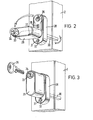
- FIGURE 2 is a front perspective detail view of the locking handle of the fastener shown in the open position;
- FIGURE 3 is a detail view similar to Figure 2 but with the handle shown in the locked closed position;
- FIGURE 4 is a detail exploded view of a bolt assembly; and
- FIGURE 5 is a detail exploded view of an alternative bolt assembly.
- With reference first to Figure 1, the fastener is for use with a
member 1 such as a door or window arranged to slide relative to a fixed frame having ajamb 2 and a cill 3 on which an upstanding rail section 4 is mounted. Themember 1 has abottom rail 5 within which aroller assembly 6 is mounted and astile 7. Themember 1 and frame are conventional, and for convenience are only partially depicted. In known manner, themember 1 is arranged to open and close relative to thejamb 2. - The fastener comprises one or more bolt assemblies 8 mounted on the
stile 7, a receiver assembly 9, and lockableoperating handle assembly 10 arranged on actuation to operate the receiver assembly 9. - A bolt assembly 8 as shown in Figure 4 comprises a
bolt member 11 having acylindrical body 12 formed with ashoulder 13 tapering to aneck 14 and terminating in ahead 15. Thebolt member 11 is received within a cylindricaltubular housing 16 having arectangular mounting plate 17 at one end. Themounting plate 17 has anopening 18 through which the bolt head 15 projects and there arecountersunk holes 19 provided by means of which the bolt assembly may be secured byscrews 20 to thestile 7. - A
helical spring 21 is mounted on thebolt body 12 and is retained thereon by aplug closure 22 which is a force fit within the end of thehousing 16. One end of thespring 21 abuts the inside of theclosure 22 and the other end abuts theshoulder 13 so that thebolt member 11 is spring loaded so that thehead 15 andneck 14 project outwardly from themounting plate 17 as shown in Figure 1. Thehead 15 of thebolt member 11 may be displaced into the housing when pressure is applied to overcome the spring loading. - The bolt assembly 8 may be mounted in a wooden stile by boring or drilling a suitable clearance hole to receive the
housing 16 with themounting plate 17 being seated in a rebate so that it lies flush with the face of the stile. Each bolt assembly would be mounted to be in register with fastening locations of the receiver assembly 9. - The receiver assembly 9 comprises two similar flat bars or rails of which the
outer retainer rail 23 overlies aninner guide rail 24 for relative limited sliding movement. Eachrail openings slidable retainer rail 23 is held and supported on therail 24 for relative movement by means of anactuator 27 associated with thehandle assembly 10. Therails rails - The key-
hole openings bolt head 15. The narrow slot portion of at least the opening 25 in theretainer rail 23 is sufficient to clear just theneck 14 of the bolt member so that when abolt member 11 is received in two alignedopenings retainer rail 23 is moved downwardly, the head is trapped and secured as the narrow portion of thehole 25 extends around theneck 14 with the head being received within thehole 26 in the fixed inner rail. - The
handle assembly 10 as shown in Figures 1, 2 and 3 comprises anescutcheon 28 mounting ahandle 29 carrying asquare section spindle 30 which extends through theescutcheon 28 and is turned by the handle. Theescutcheon 28 has fixingholes 31 for securing thehandle 29 and escutcheon to the front face of thejamb 2 byscrews 32. Thehandle 29 is pivotally mounted on theescutcheon 28, and remote from the pivot axis the handle mounts a spring loadedcylinder lock 33 having arotatable cylinder 34 operable by akey 35. Thelock 33 has a plunger (not shown) which extends from the rear of the lock and this is arranged to be received in a receiver formed by anopening 36 in the escutcheon. - As will be appreciated from the two views of Figures 2 and 3, when the
lock 33 is unlocked (Figure 2), thehandle 29 can be rotated to turn thespindle 30. When the handle is in the locking position (Figure 3), thelock 33 may be operated by thekey 35 to lock thecylinder 34 against turning with the plunger engaging in thehole 36 to secure thehandle 29 in that position. - To ensure that the
handle 29 is easily located in the locking position, adetent 37 is provided in the rear face of the handle to engage with ashallow recess 38 formed in theescutcheon 28. By this detent, adequate "feel" and "hold" on rotating the handle is achieved for the user. - The rotation of the
handle 29 and the spindle operates theactuator 27 for theretainer rail 23 mounted on theguide rail 24. The detail of theactuator 27 is not shown but includes a quadrant or toothed drive member which is turned by the spindle. This drive member is coupled to theretainer rail 23 and on movement by the spindle causes the retainer rail to move relative to the guide rail to alter the registration of the pairs of outer and inner key-hole openings - Following the above description of the construction, it will now be appreciated that in use of the fastener, the receiver assembly 9 and handle
assembly 10 are mounted on ajamb 2 with the required number of bolt assemblies 8 mounted at positions spaced along thestile 7 in alignment with the key-hole openings - As the
member 1 is closed onto thejamb 2 when thehandle 29 is in the unlocked position, the bolt heads 15 enter into respective alignedopenings handle 29 theretainer rail 23 is moved downwards so that the bolt heads 15 are trapped by theirnecks 14 engaged in the narrow part of theopenings 25. If desired, thehandle 29 may be locked by using the key 35. - If the
member 1 is open and thehandle 29 should be in the closed or locking position, then on closing movement so that the bolt heads 15 strike the receiver assembly 9, theheads 15 cannot be received behind theretainer rail 23 and the bolts are merely pushed back into their respective housings. By this action the bolt acts as buffers causing the door or window member to rebound slightly and, importantly, no damage is sustained to the receiver assembly or the jamb or the stile. - In the alternative form of bolt assembly depicted in Figure 5, the
bolt member 11 andhousing 16 are very similar to those first described with reference to Figure 4. However, in this assembly, the bolt member has a threadedend 39 arranged to engage anut 40 located against rotation in a hexagonal bore in thehousing 16. By this arrangement the spring loading and extent of thebolt head 15 from the mountingplate 17 may be adjusted by rotating thebolt member 11. This alternative may be provided where fine adjustment on installation is required. - As will be understood, in fitting the invented fastener, it is possible to fit the receiver assembly to the jamb by simple operations, and the stile of the window or door merely has to be bored or drilled to receive the bolt assemblies. The operations are principally face fixings which are preferred on installation and assembly.
- The fastener can be used, if desired, with the receiver assembly mounted on the stile and the bolt assemblies carried on the jamb. The disposition is at the preference of the user or installer.
- The fastener can be used with timber or with metal frames having a hollow or semi-hollow profile. In the latter case, designed sections and/or secondary mounting plates may be used.
- The handle assembly may be made without the cylinder lock and a simple sprung loaded plunger with a manual release knob may be employed, or a positive detent retainer may be provided. However, one advantage of the use of the cylinder lock in the construction shown is that of security for it is difficult to apply leverage or other force to the handle to break the lock mechanism.
- In accordance with the type of locking or fastening required for the door or window, the handle assembly may include an additional handle on the opposed side of the stile for operation of the fastener from both sides of the door or window.
- Other advantages and merits of this invention will be apparent to those skilled in the art.
Claims (6)
Priority Applications (1)
| Application Number | Priority Date | Filing Date | Title |
|---|---|---|---|
| AT83106713T ATE22590T1 (en) | 1982-07-24 | 1983-07-08 | SLIDING DOOR OR WINDOW CLOSURE. |
Applications Claiming Priority (2)
| Application Number | Priority Date | Filing Date | Title |
|---|---|---|---|
| GB08221460A GB2124291B (en) | 1982-07-24 | 1982-07-24 | Fastener for sliding doors or windows |
| GB8221460 | 1982-07-24 |
Publications (3)
| Publication Number | Publication Date |
|---|---|
| EP0100010A2 true EP0100010A2 (en) | 1984-02-08 |
| EP0100010A3 EP0100010A3 (en) | 1984-05-16 |
| EP0100010B1 EP0100010B1 (en) | 1986-10-01 |
Family
ID=10531887
Family Applications (1)
| Application Number | Title | Priority Date | Filing Date |
|---|---|---|---|
| EP83106713A Expired EP0100010B1 (en) | 1982-07-24 | 1983-07-08 | Fastener for sliding doors and windows |
Country Status (16)
| Country | Link |
|---|---|
| US (1) | US4500122A (en) |
| EP (1) | EP0100010B1 (en) |
| JP (1) | JPS5938470A (en) |
| KR (1) | KR840005513A (en) |
| AT (1) | ATE22590T1 (en) |
| AU (1) | AU551558B2 (en) |
| CA (1) | CA1210790A (en) |
| DE (1) | DE3366588D1 (en) |
| DK (1) | DK324583A (en) |
| ES (1) | ES524378A0 (en) |
| GB (1) | GB2124291B (en) |
| IE (1) | IE54358B1 (en) |
| IN (1) | IN159747B (en) |
| NO (1) | NO160535C (en) |
| NZ (1) | NZ204909A (en) |
| ZA (1) | ZA835022B (en) |
Cited By (6)
| Publication number | Priority date | Publication date | Assignee | Title |
|---|---|---|---|---|
| EP0495644A1 (en) * | 1991-01-17 | 1992-07-22 | Marvin Lumber And Cedar Co. | Sliding door locking device |
| EP0546336A1 (en) * | 1991-11-11 | 1993-06-16 | SCHÜRING GMBH & CO. FENSTERTECHNOLOGIE KG | Fastener for sliding doors and windows |
| EP0727525A3 (en) * | 1995-02-14 | 1996-12-04 | Brammer Systems Ltd | Lockable linkage assembly |
| EP2860333A1 (en) | 2013-10-14 | 2015-04-15 | Roto Frank Ag | Lock assembly for closing two sliding wings |
| EP3000955A1 (en) | 2014-09-26 | 2016-03-30 | Alutec Oy | Glazing arrangement |
| CN106193857A (en) * | 2016-08-08 | 2016-12-07 | 广东坚朗五金制品股份有限公司 | Door and window anti-mistake device and door and window |
Families Citing this family (53)
| Publication number | Priority date | Publication date | Assignee | Title |
|---|---|---|---|---|
| IE57110B1 (en) * | 1985-11-12 | 1992-04-22 | Valentine Patrick Galvin | Improvements in security grilles |
| GB2197381B (en) * | 1986-10-29 | 1990-03-28 | Wong Kwan Yu | Sliding gate with lockable latch mechanism. |
| US4891921A (en) * | 1987-03-30 | 1990-01-09 | Peachtree Doors, Inc. | Sliding door assembly with weather seal structure |
| US4989908A (en) * | 1990-08-13 | 1991-02-05 | Futch Clark R | Latching device for sliding door/window |
| US5290077A (en) * | 1992-01-14 | 1994-03-01 | W&F Manufacturing, Inc. | Multipoint door lock assembly |
| AU651051B3 (en) * | 1993-08-13 | 1994-07-07 | Stuart Peter Kielar | Support structure |
| BR9606389A (en) * | 1995-05-10 | 1998-01-06 | Edo Dol | Detachable closure set and adjustment process |
| US6139070A (en) * | 1997-04-10 | 2000-10-31 | Truth Hardware Corporation | Integrated power window lock |
| DE19919554C2 (en) * | 1999-03-31 | 2002-09-05 | Hoermann Kg | Torverriegelungsvorrichtung |
| EP1041230A3 (en) * | 1999-03-31 | 2003-01-29 | Hörmann Kg Amshausen | Door locking device, in particular for up-and-over door |
| US6779310B2 (en) * | 1999-06-09 | 2004-08-24 | Steven Grover | Secure public storage lockers |
| US7090263B2 (en) * | 2001-05-04 | 2006-08-15 | Spx Corporation | Door latching device and method |
| US6637784B1 (en) * | 2001-09-27 | 2003-10-28 | Builders Hardware Inc. | One-touch-actuated multipoint latch system for doors and windows |
| US6871451B2 (en) * | 2002-03-27 | 2005-03-29 | Newell Operating Company | Multipoint lock assembly |
| US20040122780A1 (en) * | 2002-04-02 | 2004-06-24 | Devar Rodney C | Universal delivery and collection box unit |
| DK175999B1 (en) * | 2003-09-23 | 2005-11-14 | Vkr Holding As | Window or door construction with a locking tab |
| US7246829B1 (en) * | 2004-01-27 | 2007-07-24 | Balsbaugh Vernon L | Sliding door latch for handicapped people |
| US7404306B2 (en) * | 2004-01-29 | 2008-07-29 | Newell Operating Company | Multi-point door lock and offset extension bolt assembly |
| US8876172B2 (en) * | 2004-03-05 | 2014-11-04 | Triteq Lock And Security, Llc | Vending machine lock with motor controlled slide-bar and hook mechanism and electronic access |
| US8661862B2 (en) * | 2004-06-29 | 2014-03-04 | The United States Postal Service | Cluster box mail delivery unit having security features |
| US7168745B2 (en) * | 2004-09-28 | 2007-01-30 | Mohammad Ali Jamnia | Device for latching a cabinet door |
| US20060137414A1 (en) * | 2004-10-12 | 2006-06-29 | Triteq Lock And Security Llc | Vending-machine lock with motor-controlled slide-bar and hook mechanism |
| US20060086057A1 (en) * | 2004-10-22 | 2006-04-27 | Rasenberger Kurt E | Protective storm windows |
| USD745765S1 (en) | 2005-06-29 | 2015-12-15 | United States Postal Service | Cluster box mail delivery unit |
| DE202005019354U1 (en) * | 2005-12-10 | 2006-03-16 | Carl Fuhr Gmbh & Co. Kg | locking |
| US20080053010A1 (en) * | 2006-09-06 | 2008-03-06 | Clyde Allen | Lockable shutter assembly |
| US7946080B2 (en) * | 2007-01-29 | 2011-05-24 | Newell Operating Company | Lock assembly |
| US8112954B2 (en) * | 2007-06-08 | 2012-02-14 | Dirtt Environmental Solutions Ltd. | Lock and seal system for sliding doors |
| US7909419B2 (en) * | 2008-05-07 | 2011-03-22 | Spacesaver Corporation | Restricted access storage compartment |
| US8348308B2 (en) | 2008-12-19 | 2013-01-08 | Amesbury Group, Inc. | High security lock for door |
| US20100236301A1 (en) * | 2009-03-19 | 2010-09-23 | Demster Stanley J | lock |
| US8522853B2 (en) * | 2009-10-21 | 2013-09-03 | Won-Door Corporation | Closure assemblies for fire doors, fire doors including such closure assemblies and methods of locking fire doors |
| US9297181B2 (en) * | 2011-05-11 | 2016-03-29 | Mario Gasparetto | Arc proof door assembly |
| US8939474B2 (en) * | 2011-06-03 | 2015-01-27 | Amesbury Group, Inc. | Lock with sliding locking elements |
| US9428937B2 (en) | 2011-07-22 | 2016-08-30 | Amesbury Group, Inc. | Multi-point lock having sequentially-actuated locking elements |
| US8550535B1 (en) * | 2012-08-28 | 2013-10-08 | International Truck Intellectual Property Company, Llc | Taper door connector strategy |
| CN104718339B (en) | 2012-08-31 | 2016-11-23 | 埃美斯博瑞集团有限公司 | Passive door latch mechanism |
| US9637957B2 (en) | 2012-11-06 | 2017-05-02 | Amesbury Group, Inc. | Automatically-extending remote door lock bolts |
| US9797167B2 (en) * | 2013-11-05 | 2017-10-24 | Dee Zee, Inc. | Locking mechanisms and toolboxes including locking mechanisms |
| CA2964792A1 (en) | 2014-10-16 | 2016-04-21 | Amesbury Group, Inc. | Opposed hook sliding door lock |
| CN106150194B (en) * | 2016-08-01 | 2018-09-11 | 广东坚朗五金制品股份有限公司 | Door and window mistake preventing device and door and window |
| US10968661B2 (en) | 2016-08-17 | 2021-04-06 | Amesbury Group, Inc. | Locking system having an electronic deadbolt |
| US11377875B2 (en) * | 2016-09-19 | 2022-07-05 | Level Home, Inc. | Deadbolt position sensing |
| CN110546340A (en) | 2017-04-18 | 2019-12-06 | 埃美斯博瑞集团有限公司 | Modular Electronic Latch System |
| US10808424B2 (en) | 2017-05-01 | 2020-10-20 | Amesbury Group, Inc. | Modular multi-point lock |
| CN109296258A (en) | 2017-07-25 | 2019-02-01 | 埃美斯博瑞集团有限公司 | Entry handle for sliding door |
| CA3036398A1 (en) | 2018-03-12 | 2019-09-12 | Amesbury Group, Inc. | Electronic deadbolt systems |
| DE102018205367A1 (en) * | 2018-04-10 | 2019-10-10 | Roto Frank Ag | Lock for a building closure element, closing part for a lock arrangement, lock arrangement and building closure element |
| US11834866B2 (en) | 2018-11-06 | 2023-12-05 | Amesbury Group, Inc. | Flexible coupling for electronic deadbolt systems |
| US11661771B2 (en) | 2018-11-13 | 2023-05-30 | Amesbury Group, Inc. | Electronic drive for door locks |
| GB2584332B (en) * | 2019-05-31 | 2023-04-26 | Gretsch Unitas Ltd | A cam arrangement |
| DE102019117862A1 (en) * | 2019-07-02 | 2021-01-07 | Maco Technologie Gmbh | Fitting part |
| US12326034B2 (en) * | 2021-11-04 | 2025-06-10 | Rhino Metals, Inc. | Safe locking mechanisms and related apparatus |
Family Cites Families (10)
| Publication number | Priority date | Publication date | Assignee | Title |
|---|---|---|---|---|
| US1036325A (en) * | 1911-11-18 | 1912-08-20 | Charles L Perry | Concealed car-door lock. |
| US1398044A (en) * | 1920-06-05 | 1921-11-22 | Sheinman Morris | Lock |
| US1438547A (en) * | 1921-09-26 | 1922-12-12 | Lyon Metallic Mfg Company | Locker |
| US3222897A (en) * | 1962-12-03 | 1965-12-14 | Northrop Architectural Systems | Latch mechanism |
| US3213652A (en) * | 1963-06-24 | 1965-10-26 | Tucker Morton | Latch device for sliding door structure |
| US3353855A (en) * | 1965-04-20 | 1967-11-21 | Crossly Window Corp | Lock mechanism for a sliding panel |
| BE790484A (en) * | 1971-10-27 | 1973-02-15 | Goodyear Aerospace Corp | LOCK FOR HANDLING CONTAINER DOOR |
| DE2538942A1 (en) * | 1975-09-02 | 1977-03-03 | Herbert Didczys | Window locking handle with cylinder lock - has lock off centre of operating shaft with lock core engaging screw hole in base |
| US4025096A (en) * | 1975-12-24 | 1977-05-24 | Adams Rite Products, Inc. | Latch mechanism for cabinet closure means |
| GB2092659B (en) * | 1981-02-07 | 1985-06-26 | Fullard Donald Malcolm | Fastening mechanisms |
-
1982
- 1982-07-24 GB GB08221460A patent/GB2124291B/en not_active Expired
-
1983
- 1983-07-07 US US06/511,587 patent/US4500122A/en not_active Expired - Fee Related
- 1983-07-08 IN IN468/DEL/83A patent/IN159747B/en unknown
- 1983-07-08 EP EP83106713A patent/EP0100010B1/en not_active Expired
- 1983-07-08 DE DE8383106713T patent/DE3366588D1/en not_active Expired
- 1983-07-08 AT AT83106713T patent/ATE22590T1/en active
- 1983-07-11 ZA ZA835022A patent/ZA835022B/en unknown
- 1983-07-14 AU AU16827/83A patent/AU551558B2/en not_active Ceased
- 1983-07-14 IE IE1640/83A patent/IE54358B1/en not_active IP Right Cessation
- 1983-07-14 DK DK324583A patent/DK324583A/en not_active Application Discontinuation
- 1983-07-15 NZ NZ204909A patent/NZ204909A/en unknown
- 1983-07-22 ES ES524378A patent/ES524378A0/en active Granted
- 1983-07-22 NO NO832679A patent/NO160535C/en unknown
- 1983-07-22 CA CA000433057A patent/CA1210790A/en not_active Expired
- 1983-07-23 KR KR1019830003408A patent/KR840005513A/en not_active Withdrawn
- 1983-07-25 JP JP58135653A patent/JPS5938470A/en active Granted
Cited By (6)
| Publication number | Priority date | Publication date | Assignee | Title |
|---|---|---|---|---|
| EP0495644A1 (en) * | 1991-01-17 | 1992-07-22 | Marvin Lumber And Cedar Co. | Sliding door locking device |
| EP0546336A1 (en) * | 1991-11-11 | 1993-06-16 | SCHÜRING GMBH & CO. FENSTERTECHNOLOGIE KG | Fastener for sliding doors and windows |
| EP0727525A3 (en) * | 1995-02-14 | 1996-12-04 | Brammer Systems Ltd | Lockable linkage assembly |
| EP2860333A1 (en) | 2013-10-14 | 2015-04-15 | Roto Frank Ag | Lock assembly for closing two sliding wings |
| EP3000955A1 (en) | 2014-09-26 | 2016-03-30 | Alutec Oy | Glazing arrangement |
| CN106193857A (en) * | 2016-08-08 | 2016-12-07 | 广东坚朗五金制品股份有限公司 | Door and window anti-mistake device and door and window |
Also Published As
| Publication number | Publication date |
|---|---|
| JPH0261593B2 (en) | 1990-12-20 |
| EP0100010B1 (en) | 1986-10-01 |
| GB2124291B (en) | 1985-10-30 |
| KR840005513A (en) | 1984-11-14 |
| ES8406619A1 (en) | 1984-07-01 |
| DE3366588D1 (en) | 1986-11-06 |
| ZA835022B (en) | 1984-09-26 |
| AU551558B2 (en) | 1986-05-01 |
| NZ204909A (en) | 1985-12-13 |
| IE831640L (en) | 1984-01-24 |
| EP0100010A3 (en) | 1984-05-16 |
| US4500122A (en) | 1985-02-19 |
| NO832679L (en) | 1984-01-25 |
| ES524378A0 (en) | 1984-07-01 |
| IE54358B1 (en) | 1989-08-30 |
| CA1210790A (en) | 1986-09-02 |
| DK324583A (en) | 1984-01-25 |
| NO160535C (en) | 1989-04-26 |
| DK324583D0 (en) | 1983-07-14 |
| GB2124291A (en) | 1984-02-15 |
| JPS5938470A (en) | 1984-03-02 |
| IN159747B (en) | 1987-06-06 |
| AU1682783A (en) | 1984-01-26 |
| NO160535B (en) | 1989-01-16 |
| ATE22590T1 (en) | 1986-10-15 |
Similar Documents
| Publication | Publication Date | Title |
|---|---|---|
| US4500122A (en) | Fastener for sliding doors or windows | |
| US7404306B2 (en) | Multi-point door lock and offset extension bolt assembly | |
| US4754624A (en) | Lock assembly for sliding doors | |
| US6217087B1 (en) | Lock mechanism | |
| US5951068A (en) | Lock for sliding door | |
| US5820173A (en) | Lock mechanism | |
| US5620216A (en) | Lock mechanism | |
| US5203596A (en) | Lock assembly for a sliding window, or the like | |
| US6666486B1 (en) | Slide bolt unit | |
| US20080150300A1 (en) | Multipoint Lock Assembly | |
| US20150284976A1 (en) | Strike assembly | |
| US5581942A (en) | Method for the installation of a sash in the frame of a roof window | |
| US4867491A (en) | Locking device for doors or windows including means for locking the square-sectioned handle-bar of the handle | |
| US6629713B1 (en) | Dead bolt lock assembly for sliding doors and/or windows | |
| GB2211882A (en) | Improvements in or relating to fasteners | |
| US4846514A (en) | Door latch apparatus | |
| CA2764072C (en) | Multi-point lock assembly | |
| WO2006119486A2 (en) | Locking mechanism and method | |
| US4093284A (en) | Door construction | |
| GB2233035A (en) | Espagnolette type locking device | |
| US20050086879A1 (en) | Retainer for prehung door | |
| GB2301141A (en) | Locking device | |
| GB2226358A (en) | Improvements in or relating to handle assemblies | |
| GB2120311A (en) | Locks | |
| GB2536224A (en) | Lock |
Legal Events
| Date | Code | Title | Description |
|---|---|---|---|
| PUAI | Public reference made under article 153(3) epc to a published international application that has entered the european phase |
Free format text: ORIGINAL CODE: 0009012 |
|
| 17P | Request for examination filed |
Effective date: 19830714 |
|
| AK | Designated contracting states |
Designated state(s): AT BE CH DE FR GB IT LI LU NL SE |
|
| PUAL | Search report despatched |
Free format text: ORIGINAL CODE: 0009013 |
|
| AK | Designated contracting states |
Designated state(s): AT BE CH DE FR GB IT LI LU NL SE |
|
| RAP1 | Party data changed (applicant data changed or rights of an application transferred) |
Owner name: HARDWARE & SYSTEM PATENTS LIMITED |
|
| GRAA | (expected) grant |
Free format text: ORIGINAL CODE: 0009210 |
|
| AK | Designated contracting states |
Kind code of ref document: B1 Designated state(s): AT BE CH DE FR GB IT LI LU NL SE |
|
| PG25 | Lapsed in a contracting state [announced via postgrant information from national office to epo] |
Ref country code: LI Effective date: 19861001 Ref country code: CH Effective date: 19861001 Ref country code: AT Effective date: 19861001 |
|
| REF | Corresponds to: |
Ref document number: 22590 Country of ref document: AT Date of ref document: 19861015 Kind code of ref document: T |
|
| PG25 | Lapsed in a contracting state [announced via postgrant information from national office to epo] |
Ref country code: SE Effective date: 19861031 |
|
| REF | Corresponds to: |
Ref document number: 3366588 Country of ref document: DE Date of ref document: 19861106 |
|
| ITF | It: translation for a ep patent filed | ||
| ET | Fr: translation filed | ||
| REG | Reference to a national code |
Ref country code: CH Ref legal event code: PL |
|
| PLBE | No opposition filed within time limit |
Free format text: ORIGINAL CODE: 0009261 |
|
| STAA | Information on the status of an ep patent application or granted ep patent |
Free format text: STATUS: NO OPPOSITION FILED WITHIN TIME LIMIT |
|
| PG25 | Lapsed in a contracting state [announced via postgrant information from national office to epo] |
Ref country code: LU Free format text: LAPSE BECAUSE OF NON-PAYMENT OF DUE FEES Effective date: 19870731 |
|
| 26N | No opposition filed | ||
| ITTA | It: last paid annual fee | ||
| PGFP | Annual fee paid to national office [announced via postgrant information from national office to epo] |
Ref country code: FR Payment date: 19900619 Year of fee payment: 8 |
|
| PGFP | Annual fee paid to national office [announced via postgrant information from national office to epo] |
Ref country code: DE Payment date: 19900726 Year of fee payment: 8 |
|
| PG25 | Lapsed in a contracting state [announced via postgrant information from national office to epo] |
Ref country code: FR Effective date: 19920331 |
|
| PG25 | Lapsed in a contracting state [announced via postgrant information from national office to epo] |
Ref country code: DE Effective date: 19920401 |
|
| REG | Reference to a national code |
Ref country code: FR Ref legal event code: ST |
|
| PGFP | Annual fee paid to national office [announced via postgrant information from national office to epo] |
Ref country code: BE Payment date: 19920618 Year of fee payment: 10 |
|
| PGFP | Annual fee paid to national office [announced via postgrant information from national office to epo] |
Ref country code: NL Payment date: 19920731 Year of fee payment: 10 |
|
| PG25 | Lapsed in a contracting state [announced via postgrant information from national office to epo] |
Ref country code: BE Effective date: 19930731 |
|
| BERE | Be: lapsed |
Owner name: HARDWARE & SYSTEM PATENTS LTD Effective date: 19930731 |
|
| PG25 | Lapsed in a contracting state [announced via postgrant information from national office to epo] |
Ref country code: NL Effective date: 19940201 |
|
| NLV4 | Nl: lapsed or anulled due to non-payment of the annual fee | ||
| PGFP | Annual fee paid to national office [announced via postgrant information from national office to epo] |
Ref country code: GB Payment date: 19970521 Year of fee payment: 15 |
|
| PG25 | Lapsed in a contracting state [announced via postgrant information from national office to epo] |
Ref country code: GB Free format text: LAPSE BECAUSE OF NON-PAYMENT OF DUE FEES Effective date: 19980708 |
|
| GBPC | Gb: european patent ceased through non-payment of renewal fee |
Effective date: 19980708 |