EP0102469A1 - Poutre garniture de frein pour freins à disques à garniture partielle, en particulier de véhicules ferroviaires - Google Patents
Poutre garniture de frein pour freins à disques à garniture partielle, en particulier de véhicules ferroviaires Download PDFInfo
- Publication number
- EP0102469A1 EP0102469A1 EP83106285A EP83106285A EP0102469A1 EP 0102469 A1 EP0102469 A1 EP 0102469A1 EP 83106285 A EP83106285 A EP 83106285A EP 83106285 A EP83106285 A EP 83106285A EP 0102469 A1 EP0102469 A1 EP 0102469A1
- Authority
- EP
- European Patent Office
- Prior art keywords
- friction lining
- friction
- lining elements
- elements
- brake pad
- Prior art date
- Legal status (The legal status is an assumption and is not a legal conclusion. Google has not performed a legal analysis and makes no representation as to the accuracy of the status listed.)
- Granted
Links
- 239000002184 metal Substances 0.000 claims description 10
- 229920001971 elastomer Polymers 0.000 claims description 3
- 239000000806 elastomer Substances 0.000 claims description 3
- 230000000284 resting effect Effects 0.000 claims description 2
- 239000010410 layer Substances 0.000 description 31
- 239000000969 carrier Substances 0.000 description 7
- 238000013461 design Methods 0.000 description 7
- 238000010276 construction Methods 0.000 description 3
- 238000013016 damping Methods 0.000 description 3
- 229910000639 Spring steel Inorganic materials 0.000 description 2
- 230000006835 compression Effects 0.000 description 2
- 238000007906 compression Methods 0.000 description 2
- 238000006073 displacement reaction Methods 0.000 description 2
- 230000000694 effects Effects 0.000 description 2
- 239000000463 material Substances 0.000 description 2
- 238000013459 approach Methods 0.000 description 1
- 230000005489 elastic deformation Effects 0.000 description 1
- 239000002783 friction material Substances 0.000 description 1
- 238000009434 installation Methods 0.000 description 1
- 239000011229 interlayer Substances 0.000 description 1
- 238000000034 method Methods 0.000 description 1
- 238000012986 modification Methods 0.000 description 1
- 230000004048 modification Effects 0.000 description 1
- 238000013021 overheating Methods 0.000 description 1
- 230000000149 penetrating effect Effects 0.000 description 1
Images


Classifications
-
- F—MECHANICAL ENGINEERING; LIGHTING; HEATING; WEAPONS; BLASTING
- F16—ENGINEERING ELEMENTS AND UNITS; GENERAL MEASURES FOR PRODUCING AND MAINTAINING EFFECTIVE FUNCTIONING OF MACHINES OR INSTALLATIONS; THERMAL INSULATION IN GENERAL
- F16D—COUPLINGS FOR TRANSMITTING ROTATION; CLUTCHES; BRAKES
- F16D69/00—Friction linings; Attachment thereof; Selection of coacting friction substances or surfaces
- F16D69/04—Attachment of linings
- F16D69/0408—Attachment of linings specially adapted for plane linings
-
- F—MECHANICAL ENGINEERING; LIGHTING; HEATING; WEAPONS; BLASTING
- F16—ENGINEERING ELEMENTS AND UNITS; GENERAL MEASURES FOR PRODUCING AND MAINTAINING EFFECTIVE FUNCTIONING OF MACHINES OR INSTALLATIONS; THERMAL INSULATION IN GENERAL
- F16D—COUPLINGS FOR TRANSMITTING ROTATION; CLUTCHES; BRAKES
- F16D65/00—Parts or details
- F16D65/0006—Noise or vibration control
-
- F—MECHANICAL ENGINEERING; LIGHTING; HEATING; WEAPONS; BLASTING
- F16—ENGINEERING ELEMENTS AND UNITS; GENERAL MEASURES FOR PRODUCING AND MAINTAINING EFFECTIVE FUNCTIONING OF MACHINES OR INSTALLATIONS; THERMAL INSULATION IN GENERAL
- F16D—COUPLINGS FOR TRANSMITTING ROTATION; CLUTCHES; BRAKES
- F16D65/00—Parts or details
- F16D65/02—Braking members; Mounting thereof
-
- F—MECHANICAL ENGINEERING; LIGHTING; HEATING; WEAPONS; BLASTING
- F16—ENGINEERING ELEMENTS AND UNITS; GENERAL MEASURES FOR PRODUCING AND MAINTAINING EFFECTIVE FUNCTIONING OF MACHINES OR INSTALLATIONS; THERMAL INSULATION IN GENERAL
- F16D—COUPLINGS FOR TRANSMITTING ROTATION; CLUTCHES; BRAKES
- F16D69/00—Friction linings; Attachment thereof; Selection of coacting friction substances or surfaces
- F16D2069/005—Friction linings; Attachment thereof; Selection of coacting friction substances or surfaces having a layered structure
- F16D2069/007—Friction linings; Attachment thereof; Selection of coacting friction substances or surfaces having a layered structure comprising a resilient layer
-
- F—MECHANICAL ENGINEERING; LIGHTING; HEATING; WEAPONS; BLASTING
- F16—ENGINEERING ELEMENTS AND UNITS; GENERAL MEASURES FOR PRODUCING AND MAINTAINING EFFECTIVE FUNCTIONING OF MACHINES OR INSTALLATIONS; THERMAL INSULATION IN GENERAL
- F16D—COUPLINGS FOR TRANSMITTING ROTATION; CLUTCHES; BRAKES
- F16D69/00—Friction linings; Attachment thereof; Selection of coacting friction substances or surfaces
- F16D69/04—Attachment of linings
- F16D2069/0425—Attachment methods or devices
- F16D2069/0433—Connecting elements not integral with the braking member, e.g. bolts, rivets
-
- F—MECHANICAL ENGINEERING; LIGHTING; HEATING; WEAPONS; BLASTING
- F16—ENGINEERING ELEMENTS AND UNITS; GENERAL MEASURES FOR PRODUCING AND MAINTAINING EFFECTIVE FUNCTIONING OF MACHINES OR INSTALLATIONS; THERMAL INSULATION IN GENERAL
- F16D—COUPLINGS FOR TRANSMITTING ROTATION; CLUTCHES; BRAKES
- F16D69/00—Friction linings; Attachment thereof; Selection of coacting friction substances or surfaces
- F16D69/04—Attachment of linings
- F16D2069/0425—Attachment methods or devices
- F16D2069/045—Bonding
Definitions
- the invention relates to a brake lining carrier for partial brake disc brakes, in particular of rail vehicles, with a base plate which on the one hand carries a friction lining and on the other hand is releasably connected to a supporting or actuating element of the brake application device, the friction lining being divided into individual friction lining elements which are perpendicular to the The friction surface is held elastically on the base plate.
- Such brake pad carriers are known for example from DE patents 1 575 773 and 1 575 774.
- the friction linings are trapezoidal in shape when viewed from above and can be classified into two size classes; within each size class, the friction linings are of identical design.
- the friction linings are connected to one another at a relatively large distance from one another by at least a plurality of lining carrier plates, but preferably all of the friction linings.
- the lining carrier plate can consist of a woven mat or a sheet metal part corrugated perpendicular to the friction surface or lying on a correspondingly corrugated surface of the base plate, in any case the support plate is elastically deformable perpendicular to the friction surface.
- each lining carrier plate is by means of bolt-shaped connecting elements held in the base plate clamped onto the base plate with a corresponding elastic deformation of the lining carrier plate.
- brake shoe carriers articulated on the application device which have an elongated dovetail guide on the brake disk side, into which a dovetail provided on the rear side of a brake lining can be inserted and locked.
- a brake shoe carrier can be found, for example, in DE-OS 25 47 530.
- an at least partial decoupling of the individual friction linings from the base plate and a large and strong mutual abutment of the individual friction linings with one another should take place, whereby squeaking noises are avoided on the one hand by uncoupling vibratable parts and on the other hand by friction damping or at least alleviated.
- the holder of the friction linings In order to enable long operating times, it must be durable, the assembly of the brake pad carrier must be possible in a simple manner. Finally, as in the prior art, it should be possible to achieve a uniform contact pattern for each individual friction lining as well as for all friction linings belonging to a brake lining carrier by means of suitable, elastic mounting of the friction linings, in order to avoid local overstressing and overheating of both the friction linings and the brake disk. Furthermore, the possibility is to be offered to be able to use the brake pad carrier in connection with conventional brake shoe carriers of rail vehicle disc brakes.
- the base plate is designed in its edge region as a socket, that the friction lining elements, which together form a friction lining block, are held on the socket, the individual friction lining elements having a displacement play parallel to the friction surface, and that in the effective direction of the the friction surface occurring during braking processes, the friction lining elements can be put on one another with mutual support and can be supported together against the mount.
- the friction lining block has an almost closed shape in supervision, wherein in at least one central area there is a small recess relative to the friction lining block when the lining carrier plates each protrude beyond the friction lining elements on at least two edges or corners with holding edges which follow in the friction lining block point outside or towards the central area, on the other hand, at the remaining edges and corners, end approximately flat with the side walls of the friction lining elements, if the interrupted or all-round frame corresponds, in supervision, to the layout of the friction lining block and is formed from a retaining edge with retaining groove angled in the direction of the friction surface, and when the friction lining elements, which form the friction lining block, are clamped on the base plate with the interposition of at least one elastic intermediate layer, the holding edges pointing outwards into the holding groove and the holding edges facing
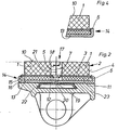
- each friction lining element 1 is also firmly connected on its rear side, as can be seen in FIG. 2, with a lining carrier plate 3 which is attached to the Friction lining block 2 protrudes outward longitudinal side 4 and on the longitudinal side / opposite corner 5 of the friction lining triangle, each with a retaining edge 6 or 7.
- the lining carrier plate 3 ends flat on the friction lining element 1 without a protruding retaining edge. The upper sides of the friction lining elements 1 facing away from the lining carrier plates 3 together form the friction surface 10.
- the retaining edges 6 and 7 are, as from FIG can be seen, slightly angled in the removal direction from the friction surface 10.
- the friction lining elements 1 are on the side of the lining carrier sheets 3 on an elastic intermediate layer 11, which corresponds approximately to that of the friction lining block 2 and which can be made of an elastomer, which, however, is also designed as a woven mat in accordance with the already mentioned DE-PS 1 575 773 can be.
- the intermediate layer 11 provided with a central recess 12 rests on a base plate 13 which, when viewed from above, has approximately the shape of the friction lining block 2 and is designed as a socket 14 in its edge region.
- the socket 14 consists of a holding edge 15 of the base plate 13 which is angled in the direction of the friction surface 10 and which forms a holding groove 16.
- the angled holding edges 6 of the friction lining elements 1 engage in the correspondingly shaped holding groove 6, as can be seen from FIG. 2.
- the socket 14 can be formed around the entire outer circumference of the base plate 13, but it can also be J, as shown in FIG. 1, interrupted, such that there are only two socket sections on the straight longitudinal sides 4 of the friction lining block .
- the friction lining block 2 has a small recess 18 in its central region 17, into which the holding edges 7 have the cross section of the recess 18 do not protrude completely.
- a bolt-like connecting member 19 engages in the recess 18, which is firmly connected to the base plate 13, for example by riveting, and / with its projecting head section 20 engages over the holding edges 7.
- the lining carrier plates 3 are thus held under prestress by compressing the intermediate layer 11 on the socket 14 and on the connecting member 19, the friction lining elements 1, however, having a certain lateral displacement play s in the plane of FIG. 1.
- the individual friction lining elements 1 joined together to form the friction lining block 2 can thus rest against one another with their entire, facing side surfaces 21.
- the base plate 13 On the side facing away from the friction lining elements 1, the base plate 13 carries an elongated J dovetail-shaped extension 22, with which it can be inserted and fastened in the dovetail guide of a brake shoe carrier 23.
- the brake shoe carrier 23 is of a conventional design, it can, for example, correspond to the aforementioned DE-OS 25 47 530.
- the brake pad carrier with the friction surface 10 is pressed against a rotating brake disc to be braked. Any unevenness in the brake disc or the individual friction lining elements 1 can be compensated for by appropriate compression of the elastic intermediate layer 11, so that a uniform contact and pressure can take place over the entire friction surface 10.
- the individual friction lining elements 1 can also adjust themselves on the elastic intermediate layer 11 in accordance with their possibly slightly different wear condition in such a way that the uniform contact pressure on the friction disk is not disturbed.
- the individual tries the friction force acting on the friction surface 10 Bring friction lining elements 1, the friction lining elements 1 are therefore pressed together on the side of the brake disc inlet, whereby on the inlet side they come out of contact with the base plate 13 or its socket - but still engaging in it - and are thus uncoupled from the base plate for noise reduction; at the same time their respective side surfaces 21 are pressed together with a force corresponding to the frictional force and thus the braking effect.
- the one or more brake-disc-side friction lining elements 1 are supported on the socket 14 and transmit the frictional force to the base plate 13, which in turn is held by the brake shoe carrier 23.
- the compression of the side surfaces 21 causes the individual friction lining elements 1 of the lining carrier block 3 to be displaceable against one another only with considerable friction, as a result of which vibrations occurring in individual friction lining elements 1 or the entire lining carrier block 2 are converted into friction work and are thus strongly damped; squeaking of the disc brakes is practically impossible.
- the individual friction lining elements 1 can be easily inserted into the socket 14 when the connecting member 19 is still missing, and assembled to form the friction lining block 2; then the connecting member 19 is inserted and connected to the base plate 13. Installation is therefore very easy.
- the holding edge 6 and the socket 14 can undergo structural modifications, as can be seen, for example, from FIGS. 3 and 4:
- the holding edge 6 is designed to be the facing carrier plate 3, and the socket 14 has a corresponding shape.
- this simpler design means that the friction lining elements 1 cannot be worn as far as is possible in the embodiment according to FIG. 2, in which the socket 14 has only a smaller height perpendicular to the friction surface 10 which overlaps with the friction lining element 1 .
- the friction lining elements 1 can, according to FIG. 5, be rounded or curved on their one side surface or longitudinal side 4 facing outwards in the assembled state of a friction lining block, the radius of curvature corresponding at least approximately to the radius of the friction lining block that can be assembled from the friction lining elements 1. This results in a friction pad block that is round in supervision.
- the retaining edges 6 are to be designed correspondingly curved, the base plate 13 can thus be designed as a circular plate with an annular frame. The version is expediently carried out closed all round. Otherwise, the brake lining carrier with friction lining elements 1 according to FIG. 5 corresponds to the features described above and therefore need not be explained further.
- the two brake pad carrier designs described above are, in addition to use with conventional brake shoe carriers 23, in whose dovetail guide several such brake pad carriers can be inserted and fastened one after the other, also for partial brake disc brakes in which the brake pads run around an axis running through their center of friction and perpendicular to the friction surface rotate.
- a brake pad carrier which has one, is particularly suitable for use with brake shoe carrier 23 according to FIG Friction lining block 2a according to FIG . 6, which is composed of ten individual friction lining elements 1 according to FIGS. 1 and 2.
- FIG. 6 which is composed of ten individual friction lining elements 1 according to FIGS. 1 and 2.
- four friction lining elements 1 are arranged side by side in such a way that they point with holding edges 7 to a common central area 17a or 17b.
- the two groups of four friction lining elements 1 formed in this way are mirror images of each other, between these two groups the two remaining friction lining elements 1 are inserted with their corner 5 having the holding edge 7 facing outward.
- the brake pad carrier thus has an oval ring-like shape with two central regions 17a and 17b and is held in each of these central regions by means of a connecting member, not shown in FIG. 6, on which a base plate 13 having the shape corresponding to the friction lining block 2a is held.
- the shape of the individual friction lining elements can be adapted to the respective requirements, for example, according to FIG. 7, it is possible to design the friction lining elements 1 in a hexagonal view, and to assemble them into an annular friction lining block.
- the friction lining elements 1 are to be provided on their sides facing outward or inward in the friction lining block with retaining edges 6 and 7, and in a version of the correspondingly designed base plate 13 or a corresponding head section of a central connecting member fastened to the base plate 13 hold.
- friction lining elements 1 have an essentially trapezoidal outline and are joined together to form the friction lining block 2b in such a way that a view of the lining carrier block 2b approximating a circular ring section is obtained: with respect to the brake disk, not shown, larger friction lining elements 1 are provided from radially inside to radially outside In contrast, in the circumferential direction, friction lining elements of the same size, but with regard to the arrangement of the retaining edges may be different, mirrored to form a central radius 24.
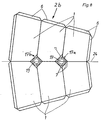
- the elastic intermediate layer 11 in all embodiments of the brake lining carrier can be used instead of a disk from Elastomer.betempted also an intermediate layer of Ge b elltem sheet, as shown in Fig. 9 and 10.
- Intermediate layer 11 between the lining carrier sheet 3 and the base plate 13 uses a plurality of layers 25 of corrugated sheet, the sheet corrugations of all layers 25 being of the same type and interlocking.
- the individual corrugated sheet layers 25 are expediently made of spring steel.
- FIG. 9 which shows a friction lining block corresponding to FIG. 6, the common corrugated axes of the layers 25 are indicated by the lines 26.
- This design of the intermediate layer 11 results in a large damping of the intermediate layer 11 in the direction perpendicular to the friction surface 10, since when the layers 25 are pressed together, the individual sheet metal layers experience a great deal of friction against one another.
- the sheets of the layers 25 can additionally be provided with friction-increasing surfaces, or intermediate layers of friction-enhancing material made of a suitable material can be inserted between the individual layers 25, whereby the aforementioned damping is increased again.
- the sheet layer intermediate layer is divided into individual sections, each of which has the shape of two adjacent friction lining elements 1 lying against one another.
- 12 is a. 1, wherein three sections 27a, 27b and 27c are shown, each section of which has a diamond-shaped shape.
- 11 shows a single section 27a, b or c in a perspective view; the lines 26 show the respective course of the corrugation both in FIG. 11 and in FIG. 12. It is essential that sections 27a, 27b and 27c are completely similar, each section can, of course, in turn, as described above for FIG. 10 several individual layers of corrugated spring steel sheet. From Fig.
- the corrugation according to the lines 26 runs parallel to the respective contacting side surfaces 21 of the two friction lining elements 1 each assigned to a section 27a, b or c. 13 is designed in such a way that in the plane running through the mentioned side surfaces 21, the sections 27a, b and c lie with their corrugation just on the base plate 13, as shown at position 28 in FIG. 13 .
- the left friction lining element 1 according to FIG. 13 is pressed down in the direction of arrow 29, the adjacent friction lining element 1 shown on the right experiences an increased force in the direction of arrow 30 upwards. If the left-hand friction lining element 1 according to FIG.
- an increased pressing-in of a friction lining element 1 results in increased support or lifting of the adjacent friction lining elements.
- a sintered metal is expediently used as the friction material for the friction lining elements 1; the combination of the friction lining elements to form the friction lining block 2, 2a or 2b counteracts crumbling of the sintered metal at least on the common side surfaces 21.
Landscapes
- Engineering & Computer Science (AREA)
- General Engineering & Computer Science (AREA)
- Mechanical Engineering (AREA)
- Braking Arrangements (AREA)
Applications Claiming Priority (2)
| Application Number | Priority Date | Filing Date | Title |
|---|---|---|---|
| DE3231279 | 1982-08-23 | ||
| DE19823231279 DE3231279A1 (de) | 1982-08-23 | 1982-08-23 | Bremsbelagtraeger fuer teilbelagscheibenbremsen, insbesondere von schienenfahrzeugen |
Publications (2)
| Publication Number | Publication Date |
|---|---|
| EP0102469A1 true EP0102469A1 (fr) | 1984-03-14 |
| EP0102469B1 EP0102469B1 (fr) | 1986-05-14 |
Family
ID=6171493
Family Applications (1)
| Application Number | Title | Priority Date | Filing Date |
|---|---|---|---|
| EP83106285A Expired EP0102469B1 (fr) | 1982-08-23 | 1983-06-28 | Poutre garniture de frein pour freins à disques à garniture partielle, en particulier de véhicules ferroviaires |
Country Status (3)
| Country | Link |
|---|---|
| US (1) | US4535874A (fr) |
| EP (1) | EP0102469B1 (fr) |
| DE (2) | DE3231279A1 (fr) |
Cited By (11)
| Publication number | Priority date | Publication date | Assignee | Title |
|---|---|---|---|---|
| EP0163182A1 (fr) * | 1984-05-15 | 1985-12-04 | LUCAS INDUSTRIES public limited company | Patin de frein pour frein à disque |
| FR2604763A1 (fr) * | 1986-10-06 | 1988-04-08 | Wabco Westinghouse | Dispositif de support pour plusieurs elements de garniture de friction |
| FR2611012A1 (fr) * | 1987-02-16 | 1988-08-19 | Valeo | Garniture de freinage a plots de materiau de friction rapportes |
| EP0336465A1 (fr) * | 1988-03-31 | 1989-10-11 | So.C.I.Mi Societa Costruzioni Industriali Milano S.P.A. | Patin de friction pour freins |
| EP0428191A1 (fr) * | 1989-11-15 | 1991-05-22 | So.C.I.Mi Societa Costruzioni Industriali Milano S.P.A. | Patin de friction pour freins à disque |
| FR2666632A1 (fr) * | 1990-09-07 | 1992-03-13 | Renault Vehicules Ind | Segment de frein a garniture de friction fractionnee. |
| EP0615074A1 (fr) * | 1993-03-12 | 1994-09-14 | Le Carbone Lorraine | Garnitures de frein à plots à fixation améliorée |
| EP0619439A1 (fr) * | 1993-04-05 | 1994-10-12 | FRENDO S.p.A. | Garniture de frein à disque avec des éléments de friction frittés |
| EP2085637A4 (fr) * | 2006-10-25 | 2011-08-31 | Akebono Brake Ind | Ensemble plaquette de frein pour frein à disque |
| EP2725257A1 (fr) * | 2012-10-23 | 2014-04-30 | Inventio AG | Sabot de frein pour une installation d'ascenseur |
| WO2016198309A1 (fr) * | 2015-06-09 | 2016-12-15 | Federal-Mogul Bremsbelag Gmbh | Support flexible d'éléments de garniture de frein dans des garnitures de frein |
Families Citing this family (26)
| Publication number | Priority date | Publication date | Assignee | Title |
|---|---|---|---|---|
| DE3317913A1 (de) * | 1983-05-17 | 1984-11-22 | Knorr-Bremse GmbH, 8000 München | Bremsbelagtraeger fuer teilbelag-scheibenbremsen |
| FR2600387B1 (fr) * | 1986-06-23 | 1990-08-10 | Wabco Westinghouse | Systeme de frein d'immobilisation pour vehicule et etrier de frein pour un tel systeme |
| GB2261711B (en) * | 1991-11-15 | 1995-09-20 | Ferodo Ltd | Brakes |
| GB9219298D0 (en) * | 1992-09-11 | 1992-10-28 | Automotive Products Plc | A disc brake |
| DE4234444C1 (de) * | 1992-10-13 | 1994-03-10 | Deutsche Bundesbahn | Temperatursensibler Bremsbelag für Scheibenbremsen, bestehend aus Belaghalter und separaten Bremsbelagteilen |
| DE4436457A1 (de) * | 1994-10-12 | 1996-04-18 | Knorr Bremse Systeme | Bremsbelag für Teilbelag-Scheibenbremsen, insbesondere von Schienenfahrzeugen |
| US6325186B1 (en) * | 2000-04-04 | 2001-12-04 | Jarlen Don | Near-net shape fabrication of friction disk ring structures |
| TW593905B (en) * | 2002-05-16 | 2004-06-21 | Knorr Bremse Systeme | Brake lining for the disk brake of a vehicle |
| US6578680B1 (en) * | 2002-05-17 | 2003-06-17 | Anstro Manufacturing, Inc. | Shim attachment |
| DE102005030619B4 (de) * | 2004-07-01 | 2008-03-27 | Knorr-Bremse Systeme für Nutzfahrzeuge GmbH | Bremsbelag für eine Scheibenbremse eines Fahrzeuges |
| JP5021468B2 (ja) * | 2004-07-01 | 2012-09-05 | クノル−ブレムゼ ジステーメ フューア シーネンファールツォイゲ ゲゼルシャフト ミット ベシュレンクテル ハフツング | 車両、特にレール車両のディスクブレーキに用いられるブレーキライニング |
| JP4006450B2 (ja) * | 2005-04-26 | 2007-11-14 | 曙ブレーキ工業株式会社 | ディスクブレーキ用摩擦材組立て体 |
| US20060289255A1 (en) * | 2005-06-25 | 2006-12-28 | Adams Philip H | Disc brake pad cushions |
| GB0523858D0 (en) * | 2005-11-24 | 2006-01-04 | Federal Mogul Friction Product | Pad assembly for use in a disc brake |
| US8505696B2 (en) * | 2007-06-29 | 2013-08-13 | Material Sciences Corporation | Brake shim and method thereof |
| DE102008039672B4 (de) * | 2008-07-24 | 2013-09-19 | Becorit Gmbh | Bremsbelag für eine Scheibenbremse und Bremsbelagsystem |
| JP5333205B2 (ja) * | 2009-12-28 | 2013-11-06 | 新日鐵住金株式会社 | 鉄道車両用ブレーキライニング |
| CN102537160A (zh) * | 2010-12-22 | 2012-07-04 | 吴佩芳 | 一种动车组制动闸片的安装结构 |
| FI125108B (fi) * | 2011-05-12 | 2015-06-15 | Kone Corp | Jarru sekä menetelmä jarrun valmistamiseksi |
| JP5985859B2 (ja) * | 2012-04-05 | 2016-09-06 | 曙ブレーキ工業株式会社 | ディスクブレーキ用摩擦パッド組立て体 |
| DE102014119492A1 (de) | 2014-12-23 | 2016-06-23 | Knorr-Bremse Systeme für Schienenfahrzeuge GmbH | Bremsbelaghalterung, Bremsbelag und Belaghalter |
| DE102015109033A1 (de) * | 2015-06-09 | 2016-12-15 | Federal-Mogul Bremsbelag Gmbh | Anordnung von Reibbelagelementen in Bremsbelägen zur Erhöhung einer Kontaktkraft zwischen den Reibbelagelementen bei Bremsbetätigung |
| JP6688578B2 (ja) * | 2015-09-14 | 2020-04-28 | 曙ブレーキ工業株式会社 | ディスクブレーキ用摩擦パッド組立て体 |
| CN108431443B (zh) * | 2015-12-25 | 2020-03-17 | 日本制铁株式会社 | 铁道车辆用制动衬片和具备该铁道车辆用制动衬片的盘式制动器 |
| CN109185374A (zh) * | 2018-10-16 | 2019-01-11 | 广东三头六臂信息科技有限公司 | 一种枕式刹车片及其使用方法 |
| DE102020115398A1 (de) | 2020-06-10 | 2021-12-16 | Knorr-Bremse Systeme für Schienenfahrzeuge GmbH | Bremsbelag für eine Scheibenbremse eines Fahrzeugs und Scheibenbremse |
Citations (6)
| Publication number | Priority date | Publication date | Assignee | Title |
|---|---|---|---|---|
| DE927905C (de) * | 1946-10-03 | 1955-05-20 | Budd Co | Bogenfoermiger Bremsschuh |
| US2713923A (en) * | 1952-12-08 | 1955-07-26 | Budd Co | Brake shoe lining for de-icing brake surfaces |
| US2904138A (en) * | 1957-02-26 | 1959-09-15 | American Brake Shoe Co | Brake shoes |
| US2943713A (en) * | 1957-02-26 | 1960-07-05 | American Brake Shoe Co | Brake shoes |
| US3198294A (en) * | 1963-12-26 | 1965-08-03 | Budd Co | Brake shoe fasteners |
| DE2547530A1 (de) * | 1975-10-23 | 1977-04-28 | Knorr Bremse Gmbh | Bremsbacke fuer scheibenbremsen |
Family Cites Families (8)
| Publication number | Priority date | Publication date | Assignee | Title |
|---|---|---|---|---|
| FR1101354A (fr) * | 1953-05-27 | 1955-10-05 | Alfa Romeo Spa | Segment de frein à articulation semi-coulissante pour automobiles |
| FR1351714A (fr) * | 1963-02-21 | 1964-02-07 | Girling Ltd | Dispositif de montage des plaques de support de patins de friction pour freins à disques de véhicules ferroviaires |
| US3895693A (en) * | 1970-02-12 | 1975-07-22 | Rene Lucien | Disc-brakes with graphite friction linings |
| GB1378886A (en) * | 1971-03-02 | 1974-12-27 | Dunlop Ltd | Brake discs |
| GB1404354A (en) * | 1972-10-27 | 1975-08-28 | Bba Group Ltd | Friction clutch devices and components therefore |
| US3923128A (en) * | 1974-02-07 | 1975-12-02 | Messier Hispano Sa | Disc brake with graphite friction shoes |
| DE2547529C2 (de) * | 1975-10-23 | 1982-10-21 | Knorr-Bremse GmbH, 8000 München | Bremsbacke für Scheibenbremsen |
| DE7901527U1 (de) * | 1979-01-20 | 1979-05-10 | Bvt Beratungs-, Verwaltungs- Und Treuhandgesellschaft Mbh, 4000 Duesseldorf | Scheibenbremse |
-
1982
- 1982-08-23 DE DE19823231279 patent/DE3231279A1/de not_active Withdrawn
-
1983
- 1983-06-28 EP EP83106285A patent/EP0102469B1/fr not_active Expired
- 1983-06-28 DE DE8383106285T patent/DE3363502D1/de not_active Expired
- 1983-08-05 US US06/520,628 patent/US4535874A/en not_active Expired - Fee Related
Patent Citations (6)
| Publication number | Priority date | Publication date | Assignee | Title |
|---|---|---|---|---|
| DE927905C (de) * | 1946-10-03 | 1955-05-20 | Budd Co | Bogenfoermiger Bremsschuh |
| US2713923A (en) * | 1952-12-08 | 1955-07-26 | Budd Co | Brake shoe lining for de-icing brake surfaces |
| US2904138A (en) * | 1957-02-26 | 1959-09-15 | American Brake Shoe Co | Brake shoes |
| US2943713A (en) * | 1957-02-26 | 1960-07-05 | American Brake Shoe Co | Brake shoes |
| US3198294A (en) * | 1963-12-26 | 1965-08-03 | Budd Co | Brake shoe fasteners |
| DE2547530A1 (de) * | 1975-10-23 | 1977-04-28 | Knorr Bremse Gmbh | Bremsbacke fuer scheibenbremsen |
Cited By (17)
| Publication number | Priority date | Publication date | Assignee | Title |
|---|---|---|---|---|
| EP0163182A1 (fr) * | 1984-05-15 | 1985-12-04 | LUCAS INDUSTRIES public limited company | Patin de frein pour frein à disque |
| FR2604763A1 (fr) * | 1986-10-06 | 1988-04-08 | Wabco Westinghouse | Dispositif de support pour plusieurs elements de garniture de friction |
| EP0263752A3 (en) * | 1986-10-06 | 1988-12-07 | Wabco Westinghouse Equipements Ferroviaires, Societe Anonyme Dite: | Support for several friction linings |
| FR2611012A1 (fr) * | 1987-02-16 | 1988-08-19 | Valeo | Garniture de freinage a plots de materiau de friction rapportes |
| EP0336465A1 (fr) * | 1988-03-31 | 1989-10-11 | So.C.I.Mi Societa Costruzioni Industriali Milano S.P.A. | Patin de friction pour freins |
| EP0428191A1 (fr) * | 1989-11-15 | 1991-05-22 | So.C.I.Mi Societa Costruzioni Industriali Milano S.P.A. | Patin de friction pour freins à disque |
| FR2666632A1 (fr) * | 1990-09-07 | 1992-03-13 | Renault Vehicules Ind | Segment de frein a garniture de friction fractionnee. |
| FR2702528A1 (fr) * | 1993-03-12 | 1994-09-16 | Lorraine Carbone | Garnitures de frein à plots à fixation améliorée. |
| EP0615074A1 (fr) * | 1993-03-12 | 1994-09-14 | Le Carbone Lorraine | Garnitures de frein à plots à fixation améliorée |
| EP0619439A1 (fr) * | 1993-04-05 | 1994-10-12 | FRENDO S.p.A. | Garniture de frein à disque avec des éléments de friction frittés |
| US5538108A (en) * | 1993-04-05 | 1996-07-23 | Frendo S.P.A. | Pad for disc brakes with sintered friction elements |
| EP2085637A4 (fr) * | 2006-10-25 | 2011-08-31 | Akebono Brake Ind | Ensemble plaquette de frein pour frein à disque |
| EP2363615A1 (fr) * | 2006-10-25 | 2011-09-07 | Akebono Brake Industry Co., Ltd. | Ensemble de plaquette de friction pour frein à disque |
| CN102287462B (zh) * | 2006-10-25 | 2014-07-30 | 曙制动器工业株式会社 | 盘形制动器用摩擦垫组装体 |
| EP2725257A1 (fr) * | 2012-10-23 | 2014-04-30 | Inventio AG | Sabot de frein pour une installation d'ascenseur |
| WO2016198309A1 (fr) * | 2015-06-09 | 2016-12-15 | Federal-Mogul Bremsbelag Gmbh | Support flexible d'éléments de garniture de frein dans des garnitures de frein |
| CN108138876A (zh) * | 2015-06-09 | 2018-06-08 | 联邦默高自动衬带有限公司 | 摩擦衬片元件在制动衬片中的灵活安装 |
Also Published As
| Publication number | Publication date |
|---|---|
| EP0102469B1 (fr) | 1986-05-14 |
| DE3363502D1 (en) | 1986-06-19 |
| US4535874A (en) | 1985-08-20 |
| DE3231279A1 (de) | 1984-02-23 |
Similar Documents
| Publication | Publication Date | Title |
|---|---|---|
| EP0102469B1 (fr) | Poutre garniture de frein pour freins à disques à garniture partielle, en particulier de véhicules ferroviaires | |
| DE60105206T2 (de) | Scheibe aus verbundwerkstoff für eine scheibenbremse | |
| DE19726674B4 (de) | Bremsscheibe | |
| DE602004000189T2 (de) | Scheibenbremsbelaghalterung | |
| DE69207328T2 (de) | Kupplung mit Verbundscheiben, insbesondere aus Kohlenstoff-Kohlenstoff-Verbundwerkstoff | |
| DE60304987T2 (de) | Scheibenbremse | |
| DE3742354C2 (de) | Reibungskupplung mit progressivem Eingriff | |
| DE4120631A1 (de) | Bremsklotz fuer scheibenbremsen | |
| DE69005072T3 (de) | Reibungskupplungsscheibe mit niedriger Trägheit, insbesondere für Kraftfahrzeuge. | |
| EP3198166A1 (fr) | Moyen de guidage pour ensemble de garniture de frein d'un frein à disque et frein à disque | |
| DE2036761A1 (de) | Kupplungsscheibe mit abgefederten metallischen oder metallkeramischen Reibbelägen | |
| DE4229613A1 (de) | Stützlager | |
| DE3323995A1 (de) | Gedrueckte membranfederkupplung mit selbsttaetigem verschleissausgleich im bereich des kippkreises | |
| EP1434951B1 (fr) | Disque de frein pour un frein a disque | |
| EP1167806B1 (fr) | Garniture de frein pour frein à disque de garniture partielle | |
| DE3507077A1 (de) | Kupplungsabdeckungsvorrichtung | |
| AT519090B1 (de) | Bremsbelag | |
| DE1211500B (de) | Bremsbacke fuer Teilbelagscheibenbremsen mit losem Bremssattel, insbesondere fuer Kraftfahrzeuge | |
| EP0552387A1 (fr) | Disque mené d'embrayage pour véhicule automobile | |
| EP1933050A1 (fr) | Dispositif d'embrayage | |
| EP0699845B1 (fr) | Agencement de disque de frein | |
| EP3341103B1 (fr) | Filtre pouvant être installé sur une bride de raccordement et insert de filtre pour celui-ci | |
| DE3427370C2 (fr) | ||
| DE2313346C3 (de) | Niederhalte- und Rückstellfeder für die Bremsbacken einer Festsattel-Teilbelagscheibenbremse | |
| DE3023333A1 (de) | Bremsbackenhalterung fuer scheibenbremsen |
Legal Events
| Date | Code | Title | Description |
|---|---|---|---|
| PUAI | Public reference made under article 153(3) epc to a published international application that has entered the european phase |
Free format text: ORIGINAL CODE: 0009012 |
|
| 17P | Request for examination filed |
Effective date: 19831220 |
|
| AK | Designated contracting states |
Designated state(s): DE FR GB IT |
|
| RAP1 | Party data changed (applicant data changed or rights of an application transferred) |
Owner name: KNORR-BREMSE AG |
|
| GRAA | (expected) grant |
Free format text: ORIGINAL CODE: 0009210 |
|
| ITF | It: translation for a ep patent filed | ||
| AK | Designated contracting states |
Kind code of ref document: B1 Designated state(s): DE FR GB IT |
|
| REF | Corresponds to: |
Ref document number: 3363502 Country of ref document: DE Date of ref document: 19860619 |
|
| ET | Fr: translation filed | ||
| PLBE | No opposition filed within time limit |
Free format text: ORIGINAL CODE: 0009261 |
|
| STAA | Information on the status of an ep patent application or granted ep patent |
Free format text: STATUS: NO OPPOSITION FILED WITHIN TIME LIMIT |
|
| 26N | No opposition filed | ||
| PGFP | Annual fee paid to national office [announced via postgrant information from national office to epo] |
Ref country code: FR Payment date: 19920428 Year of fee payment: 10 |
|
| PGFP | Annual fee paid to national office [announced via postgrant information from national office to epo] |
Ref country code: GB Payment date: 19920501 Year of fee payment: 10 |
|
| PGFP | Annual fee paid to national office [announced via postgrant information from national office to epo] |
Ref country code: DE Payment date: 19920604 Year of fee payment: 10 |
|
| PG25 | Lapsed in a contracting state [announced via postgrant information from national office to epo] |
Ref country code: GB Effective date: 19930628 |
|
| ITTA | It: last paid annual fee | ||
| GBPC | Gb: european patent ceased through non-payment of renewal fee |
Effective date: 19930628 |
|
| PG25 | Lapsed in a contracting state [announced via postgrant information from national office to epo] |
Ref country code: FR Effective date: 19940228 |
|
| PG25 | Lapsed in a contracting state [announced via postgrant information from national office to epo] |
Ref country code: DE Effective date: 19940301 |
|
| REG | Reference to a national code |
Ref country code: FR Ref legal event code: ST |