EP0103272A2 - Insulation of aluminium profiles in a fixture - Google Patents
Insulation of aluminium profiles in a fixture Download PDFInfo
- Publication number
- EP0103272A2 EP0103272A2 EP83108851A EP83108851A EP0103272A2 EP 0103272 A2 EP0103272 A2 EP 0103272A2 EP 83108851 A EP83108851 A EP 83108851A EP 83108851 A EP83108851 A EP 83108851A EP 0103272 A2 EP0103272 A2 EP 0103272A2
- Authority
- EP
- European Patent Office
- Prior art keywords
- profile
- plastic
- grooves
- portions
- fixture
- Prior art date
- Legal status (The legal status is an assumption and is not a legal conclusion. Google has not performed a legal analysis and makes no representation as to the accuracy of the status listed.)
- Granted
Links
- XAGFODPZIPBFFR-UHFFFAOYSA-N aluminium Chemical compound [Al] XAGFODPZIPBFFR-UHFFFAOYSA-N 0.000 title claims abstract description 26
- 229910052782 aluminium Inorganic materials 0.000 title claims abstract description 26
- 239000004411 aluminium Substances 0.000 title abstract 2
- 238000009413 insulation Methods 0.000 title description 8
- 239000004033 plastic Substances 0.000 claims abstract description 59
- 239000002984 plastic foam Substances 0.000 claims abstract description 46
- 239000002131 composite material Substances 0.000 claims abstract description 31
- 238000000034 method Methods 0.000 claims abstract description 9
- 238000004519 manufacturing process Methods 0.000 claims abstract description 6
- 238000005096 rolling process Methods 0.000 claims description 8
- 230000000295 complement effect Effects 0.000 claims description 2
- 238000005187 foaming Methods 0.000 description 5
- 239000000463 material Substances 0.000 description 5
- 239000012530 fluid Substances 0.000 description 3
- 238000007789 sealing Methods 0.000 description 3
- 238000006243 chemical reaction Methods 0.000 description 2
- 238000010276 construction Methods 0.000 description 2
- 230000007423 decrease Effects 0.000 description 2
- 239000006260 foam Substances 0.000 description 2
- 238000003780 insertion Methods 0.000 description 2
- 230000037431 insertion Effects 0.000 description 2
- 239000000203 mixture Substances 0.000 description 2
- XLYOFNOQVPJJNP-UHFFFAOYSA-N water Substances O XLYOFNOQVPJJNP-UHFFFAOYSA-N 0.000 description 2
- 238000002048 anodisation reaction Methods 0.000 description 1
- 239000007795 chemical reaction product Substances 0.000 description 1
- 230000003247 decreasing effect Effects 0.000 description 1
- 238000009826 distribution Methods 0.000 description 1
- 230000003670 easy-to-clean Effects 0.000 description 1
- 238000001125 extrusion Methods 0.000 description 1
- 239000006261 foam material Substances 0.000 description 1
- 239000003973 paint Substances 0.000 description 1
- 239000000047 product Substances 0.000 description 1
- 230000003014 reinforcing effect Effects 0.000 description 1
- 239000002344 surface layer Substances 0.000 description 1
- 238000009827 uniform distribution Methods 0.000 description 1
Images




Classifications
-
- E—FIXED CONSTRUCTIONS
- E06—DOORS, WINDOWS, SHUTTERS, OR ROLLER BLINDS IN GENERAL; LADDERS
- E06B—FIXED OR MOVABLE CLOSURES FOR OPENINGS IN BUILDINGS, VEHICLES, FENCES OR LIKE ENCLOSURES IN GENERAL, e.g. DOORS, WINDOWS, BLINDS, GATES
- E06B3/00—Window sashes, door leaves, or like elements for closing wall or like openings; Layout of fixed or moving closures, e.g. windows in wall or like openings; Features of rigidly-mounted outer frames relating to the mounting of wing frames
- E06B3/04—Wing frames not characterised by the manner of movement
- E06B3/263—Frames with special provision for insulation
- E06B3/267—Frames with special provision for insulation with insulating elements formed in situ
- E06B3/2675—Frames with special provision for insulation with insulating elements formed in situ combined with prefabricated insulating elements
-
- E—FIXED CONSTRUCTIONS
- E06—DOORS, WINDOWS, SHUTTERS, OR ROLLER BLINDS IN GENERAL; LADDERS
- E06B—FIXED OR MOVABLE CLOSURES FOR OPENINGS IN BUILDINGS, VEHICLES, FENCES OR LIKE ENCLOSURES IN GENERAL, e.g. DOORS, WINDOWS, BLINDS, GATES
- E06B3/00—Window sashes, door leaves, or like elements for closing wall or like openings; Layout of fixed or moving closures, e.g. windows in wall or like openings; Features of rigidly-mounted outer frames relating to the mounting of wing frames
- E06B3/04—Wing frames not characterised by the manner of movement
- E06B3/263—Frames with special provision for insulation
- E06B3/26341—Frames with special provision for insulation comprising only one metal frame member combined with an insulating frame member
-
- E—FIXED CONSTRUCTIONS
- E06—DOORS, WINDOWS, SHUTTERS, OR ROLLER BLINDS IN GENERAL; LADDERS
- E06B—FIXED OR MOVABLE CLOSURES FOR OPENINGS IN BUILDINGS, VEHICLES, FENCES OR LIKE ENCLOSURES IN GENERAL, e.g. DOORS, WINDOWS, BLINDS, GATES
- E06B3/00—Window sashes, door leaves, or like elements for closing wall or like openings; Layout of fixed or moving closures, e.g. windows in wall or like openings; Features of rigidly-mounted outer frames relating to the mounting of wing frames
- E06B3/04—Wing frames not characterised by the manner of movement
- E06B3/263—Frames with special provision for insulation
- E06B3/273—Frames with special provision for insulation with prefabricated insulating elements held in position by deformation of portions of the metal frame members
-
- E—FIXED CONSTRUCTIONS
- E06—DOORS, WINDOWS, SHUTTERS, OR ROLLER BLINDS IN GENERAL; LADDERS
- E06B—FIXED OR MOVABLE CLOSURES FOR OPENINGS IN BUILDINGS, VEHICLES, FENCES OR LIKE ENCLOSURES IN GENERAL, e.g. DOORS, WINDOWS, BLINDS, GATES
- E06B3/00—Window sashes, door leaves, or like elements for closing wall or like openings; Layout of fixed or moving closures, e.g. windows in wall or like openings; Features of rigidly-mounted outer frames relating to the mounting of wing frames
- E06B3/04—Wing frames not characterised by the manner of movement
- E06B3/263—Frames with special provision for insulation
- E06B2003/26349—Details of insulating strips
- E06B2003/26387—Performing extra functions
-
- E—FIXED CONSTRUCTIONS
- E06—DOORS, WINDOWS, SHUTTERS, OR ROLLER BLINDS IN GENERAL; LADDERS
- E06B—FIXED OR MOVABLE CLOSURES FOR OPENINGS IN BUILDINGS, VEHICLES, FENCES OR LIKE ENCLOSURES IN GENERAL, e.g. DOORS, WINDOWS, BLINDS, GATES
- E06B3/00—Window sashes, door leaves, or like elements for closing wall or like openings; Layout of fixed or moving closures, e.g. windows in wall or like openings; Features of rigidly-mounted outer frames relating to the mounting of wing frames
- E06B3/04—Wing frames not characterised by the manner of movement
- E06B3/263—Frames with special provision for insulation
- E06B2003/26349—Details of insulating strips
- E06B2003/26387—Performing extra functions
- E06B2003/26389—Holding sealing strips or forming sealing abutments
-
- Y—GENERAL TAGGING OF NEW TECHNOLOGICAL DEVELOPMENTS; GENERAL TAGGING OF CROSS-SECTIONAL TECHNOLOGIES SPANNING OVER SEVERAL SECTIONS OF THE IPC; TECHNICAL SUBJECTS COVERED BY FORMER USPC CROSS-REFERENCE ART COLLECTIONS [XRACs] AND DIGESTS
- Y10—TECHNICAL SUBJECTS COVERED BY FORMER USPC
- Y10T—TECHNICAL SUBJECTS COVERED BY FORMER US CLASSIFICATION
- Y10T428/00—Stock material or miscellaneous articles
- Y10T428/24—Structurally defined web or sheet [e.g., overall dimension, etc.]
- Y10T428/24479—Structurally defined web or sheet [e.g., overall dimension, etc.] including variation in thickness
- Y10T428/24496—Foamed or cellular component
- Y10T428/24504—Component comprises a polymer [e.g., rubber, etc.]
-
- Y—GENERAL TAGGING OF NEW TECHNOLOGICAL DEVELOPMENTS; GENERAL TAGGING OF CROSS-SECTIONAL TECHNOLOGIES SPANNING OVER SEVERAL SECTIONS OF THE IPC; TECHNICAL SUBJECTS COVERED BY FORMER USPC CROSS-REFERENCE ART COLLECTIONS [XRACs] AND DIGESTS
- Y10—TECHNICAL SUBJECTS COVERED BY FORMER USPC
- Y10T—TECHNICAL SUBJECTS COVERED BY FORMER US CLASSIFICATION
- Y10T428/00—Stock material or miscellaneous articles
- Y10T428/24—Structurally defined web or sheet [e.g., overall dimension, etc.]
- Y10T428/24479—Structurally defined web or sheet [e.g., overall dimension, etc.] including variation in thickness
- Y10T428/24562—Interlaminar spaces
-
- Y—GENERAL TAGGING OF NEW TECHNOLOGICAL DEVELOPMENTS; GENERAL TAGGING OF CROSS-SECTIONAL TECHNOLOGIES SPANNING OVER SEVERAL SECTIONS OF THE IPC; TECHNICAL SUBJECTS COVERED BY FORMER USPC CROSS-REFERENCE ART COLLECTIONS [XRACs] AND DIGESTS
- Y10—TECHNICAL SUBJECTS COVERED BY FORMER USPC
- Y10T—TECHNICAL SUBJECTS COVERED BY FORMER US CLASSIFICATION
- Y10T428/00—Stock material or miscellaneous articles
- Y10T428/24—Structurally defined web or sheet [e.g., overall dimension, etc.]
- Y10T428/24628—Nonplanar uniform thickness material
- Y10T428/24661—Forming, or cooperating to form cells
-
- Y—GENERAL TAGGING OF NEW TECHNOLOGICAL DEVELOPMENTS; GENERAL TAGGING OF CROSS-SECTIONAL TECHNOLOGIES SPANNING OVER SEVERAL SECTIONS OF THE IPC; TECHNICAL SUBJECTS COVERED BY FORMER USPC CROSS-REFERENCE ART COLLECTIONS [XRACs] AND DIGESTS
- Y10—TECHNICAL SUBJECTS COVERED BY FORMER USPC
- Y10T—TECHNICAL SUBJECTS COVERED BY FORMER US CLASSIFICATION
- Y10T428/00—Stock material or miscellaneous articles
- Y10T428/249921—Web or sheet containing structurally defined element or component
- Y10T428/249953—Composite having voids in a component [e.g., porous, cellular, etc.]
- Y10T428/249987—With nonvoid component of specified composition
- Y10T428/24999—Inorganic
Definitions
- the present invention relates to an insulated composite aluminum profile, a method for producing such aluminum profiles in a fixture and a device for manufacturing the aluminum profile.
- a drawback with said system is that the tolerances of each section and the plastic strips are added and give an end product with too big tolerances. In connection with e.g. window frames, those tolerances have given problems.
- the object of the present invention is to provide an insulated composite aluminum profile, in which close tolerances are achievable.
- Another object of the invention is to provide an insulated composite aluminum profile where the insulating plastic foam is protected by a strip of hard plastic, which is positioned in essentially the same plane or surface as the surrounding surface in order to form a resistive and easily cleanable surface without water pockets.
- the hard plastic strip also gives a certain mechanical stability to the profile.
- the present invention comprises a method for manufacturing an insulating composite profile, comprising at least two profile sections, preferably of aluminum, having grooves, which preferably are undercut, in which plastic strips, preferably manufactured by hard plastic, engage in order to interconnect the profile sections to form an enclosed space,which contains an insulating plastic foam.
- the separate profile sections are placed in a fixture, the plastic strips first being inserted in the grooves.
- the fixture determines the dimensions of the composite profile when formed.
- a plastic foam is introduced and is allowed to expand and cure, whereupon the composite profile is formed.
- the outer edges of the grooves are eventually rolled in order to fix the plastic strip and eventually to absorb clearances between the grooves and the plastic strips.
- the invention also relates to a composite profile produced according to the method and a device for producing the composite profile.
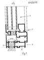
- Fig. 1 is a cross-sectional view of an insulated aluminum profile according to the invention, which is used for providing a window frame.
- fig. 1 shows a first frame 1, which is intended to support the glassing unit 2 of the window and a second frame 3.
- the two frames are composed of several, separate profile portions according to known technique.
- the frames comprise an insulation 4 of plastic foam. The insulations of the frames are made in the same manner and thus it is only described how the insulation is made on the frame 3.
- Fig. 2 is an enlarged view of the portion II-II encircled in Fig. 1.
- the frame 3 comprises a profile portion 5 facing the outside of the house, and a profile portion 6 facing the interior of the house.
- the profile portions comprise undercut grooves 7 intended to engage with complementary shaped edges 9 of a plastic strip 8, which preferably is made of hard plastic.
- a plastic strip is intended to be inserted in the grooves 7 in order to interconnect the two profile portions.
- the edges 9 of the plastic strips In order to be insertable in the grooves 7, the edges 9 of the plastic strips must easily fit in the grooves 7 and thus form a clearance in the grooves when they are inserted therein.
- the two profile portions 5, 6 are placed in a fixture.
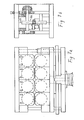
- the fixture is schematically shown in Fig. 3 and comprises two essentially vertical side portions 10 and 11.
- the side portion 10 is fixed while the side portion 11 is adjustable by means of a key system 12, which comprises two mutually engaging keys 13 and 14.
- the key 14 is adjustable as to its high position by means of gauge blocks 15, which have different sizes for different distances between the side portions 10 and 11.
- a spring 16 urges the key 13 of the side portion 11 against the free key 14. By means of the gauge block 15, the distance between the side portions 10 and 11 is carefully adjusted.
- mold portions 17a, 17b are placed.
- the mold portions are so shaped that a mold space is formed between them for receiving the composite profile.
- the fixture is loaded by first placing the lowermost mold portion 17a in the fixture - 10, 11, whereupon a composite profile 2 having the plastic strip 8 positioned in the grooves, is placed above the mold portion 17a and a new mold portion 17b is placed there above and so on.
- Each profile has a length of e.g. 6 metres and each fixture can comprise a selected number of stacked profiles.
- Fig. 4 shows a more detailed embodiment of the fixture according to the invention.
- the fixture can comprise several adjacent side portions 10, 11 so that several groups of profiles are simultaneously made.
- the space 18 which is to be filled with plastic foam is available from both ends and is closed by plugs, each provided with a valve.
- the plug is constructed to allow the exhaust of air until the foaming plastic material reaches the plug, whereupon this material closes the valve and prevents the plastic foam from being forced out of the space 18. In this manner a pressure can be built up inside the space 18.
- the insertion of the plastic foam in the space 18 is made in a known manner, whereby the two components of the plastic foam are sprayed against each other until complete mixing, whereupon the mixture is ejected through a nozzle.
- the nozzle is inserted in the plug and a suitable amount of plastic foam is ejected inside the space and is allowed to react.
- the plastic foam enters the space 18 immediately after the mixing and is ejected along the whole length of the profile so that it achieves an equal distribution.
- the reaction starts immediately and a gas, freon, is formed, which brings about the foaming and expansion of the plastic.
- an inner pressure is built up inside the space 18, which closes the valves of the plugs.
- the space 18 In order that the plastic foam shall expand in the right way and excert the intended pressure and cure within a reasonable time, the space 18 must have a temperature in the range of 30-40°C. This is easily achieved by known means.
- the mold portions 17a, 17b can be provided with bellows 20 which is shown in broken lines in Fig. 3.
- the bellow 20 is connected to an air pressure source and urges the profile out towards the respective side portion 10, 11.
- each mold portion can be provided with an insert 21, which directly abuts the plastic strip 8 and presses it downwards so that a sealing is obtained at the two edges of the plastic strip. In this manner it is avoided that the plastic foam can be squeezed out through the grooves 7. It is also possible to use the internal pressure of the plastic foam in order to urge the plastic strips outwards as is shown in Fig. 2, whereby the plastic foam, which enters the grooves 7, cannot pass further outwards.
- Another possibility to solve this problem is to provide projecting sealing edges 23 to the edges of the plastic strip as is shown in Fig. 6 in order to form a labyrinth sealing which retards the plastic foam so much that is has time to cure.
- pneumatic cylinders 19 are arranged to exert a predetermined pressure on the uppermost mold portion, compare Fig. 4.
- the profile made in this manner has a mechanical stability.
- the plastic strips, together with the aluminum profile, form essentially smooth surfaces, which are easy to clean. Above all, no water pockets are formed so that no drainage of the profile is required in connection with the plastic foam insulation. The drainage can be placed at another position. In this way, no moisture films are formed, which can influence on and decrease the insulation ability.
- FIG. 17 is a schematic, perspective view of the device for performing the method.
- Fig. 17 there is shown two aluminum profiles 5, 6 interconnected by two plastic strips 8 as previously described.
- the plastic profile has the stud 11 extending inwardly towards the space 10.
- a thin plastic pipe 28 is cut longitudinally by a sharp edge 29.
- a driving shaft 30, which cooperates with an idling roll 31 feeds the pipe to the left in Fig. 17.
- the mixed fluid is deposed by a nozzle 33 with the same velocity as the feeding speed of the pipe 28.
- the pipe is guided by the stud 11 and is inserted in the space 10 in the manner shown in Fig. 17.
- the reaction forces the fluid inside the pipe to expand and escape from the pipe 28 inside the space 10 as previously described.
- the aluminum profile may pass below a roll, which acts against the borders of the groove 7 in order to bend the borders to grip the plastic strip 8.
- the rolling machinery appears from Figs. 7a and 7b, while Fig. 8 shows the profile thus treated. From Fig. 8 it is evident that the roll presses against a border 24 of the groove 7 so that the border is bent inwards and decreases the opening of the groove 7 and clamps the neck portion 25 of the plastic strip 8. The roll is so arranged that a certain clamping force is exerted to the neck portion 25 which locks and clamps the plastic strip 8 in position.
- the rolling machinery can also comprise a measuring equipment, which monitors if the profile has achieved the desired dimensions.
- the rolling machinery appears more closely from Figs. 7a and b and comprises several rolls 26, which in several steps upset the border 24 to the shape shown in Fig. 8. Each roll can be divided into two portions which is shown by the line 27.
- the fixture can be a portion of an automatic machine, which comprises three different magazines which circulate in a closed loop circuit.
- the first magazine is loaded while simultaneously the second magazine is occupied by the foaming step and the third magazine is positioned in an outfeed station for delivery to the rolling machinery.
- a heat station in order to obtain the right temperature for foaming.
- the aluminum profile portions 5, 6 are suitably anodized before the mounting according to the present invention.
- the surface layer can be damaged during the treatment and it is thus sometimes necessary to repair the anodization. It can also be necessary to paint the surfaces after the mounting, which must be done in a relatively high heat. This is however possible with the profile according to the present invention due to the reinforcing action of the hard plastic strips 8 and by means of the mechanical locking which is achieved by the rolling.
- the plastic strip 8 is provided with a projecting stud 11, which extends along the whole length of the plastic strip.
- the stud is intended to form a locking together with the further recesses of the profile so that it is possible to connect an uninsulated'profile to the insulated profile, such as window sheets, fendering and connection profiles etc.
- the stud 28 is somewhat excentrically positioned.
- the stud is not used for locking, it is turned inside the plastic foam. Window sheets, fendering and connection profiles can thus be connected to both the inside and the outside without breaking the cold bridge.
- Figs. 9 to 12 show some embodiments of the locking possibility of this stud.
Landscapes
- Civil Engineering (AREA)
- Structural Engineering (AREA)
- Engineering & Computer Science (AREA)
- Wing Frames And Configurations (AREA)
- Laminated Bodies (AREA)
- Door And Window Frames Mounted To Openings (AREA)
- Inorganic Insulating Materials (AREA)
- Load-Engaging Elements For Cranes (AREA)
- Insulating Bodies (AREA)
- Accommodation For Nursing Or Treatment Tables (AREA)
- Flanged Joints, Insulating Joints, And Other Joints (AREA)
- Spinning Or Twisting Of Yarns (AREA)
- Casting Or Compression Moulding Of Plastics Or The Like (AREA)
- Body Structure For Vehicles (AREA)
Abstract
Description
- The present invention relates to an insulated composite aluminum profile, a method for producing such aluminum profiles in a fixture and a device for manufacturing the aluminum profile.
- At the building of windows, doors, facade portions and similar, aluminum profiles of different shapes are often used. In order to prevent or obstruct the heat transport from the interior of the house to its outside through such aluminum profiles, so called cold bridges, an insulation must be arranged between the outer and inner portions of the profile.
- In this connection it is previously known to construct the profile in two portions which are interconnected by means of insulating plastic foam.
- A method which is often used is disclosed in the Swedish patent application No. 7176/71 wherein the two portions are interconnected by means of two plastic ledges or strips in order to form an enclosed space, in which a plastic foam is allowed to expand. The plastic foam exerts a pressure and urges the profiles from each other as much as is allowed by the plastic strips.
- A drawback with said system is that the tolerances of each section and the plastic strips are added and give an end product with too big tolerances. In connection with e.g. window frames, those tolerances have given problems.
- An attempt to overcome this drawback is disclosed in the Swedish patent specification SE-B-7107649-1. Said patent specification describes that the two profile sections are manufactured connected to each other by means of two removable webs..Thus, the plastic foam is introduced in a space formed already at the manufacturing or extrusion of the aluminum profile-and is allowed to expand and cure therein. Thereupon, the webs are removed and an insulated composite profile is formed. The drawback with said construction is that the plastic foam is the only material which interconnects the two sections. A so called integral foam is used, which has a greater density at the surface than in the centre thereof. The integral foam does not have as good insulating properties as the plastic foam having homogeneous and low density. Moreover, the mechanical stability of the construction will be decreased. Finally the surface of the plastic foam will be exposed to the atmosphere and is easily affected by moisture and similar.
- The object of the present invention is to provide an insulated composite aluminum profile, in which close tolerances are achievable.
- Another object of the invention is to provide an insulated composite aluminum profile where the insulating plastic foam is protected by a strip of hard plastic, which is positioned in essentially the same plane or surface as the surrounding surface in order to form a resistive and easily cleanable surface without water pockets. The hard plastic strip also gives a certain mechanical stability to the profile.
- Thus, the present invention comprises a method for manufacturing an insulating composite profile, comprising at least two profile sections, preferably of aluminum, having grooves, which preferably are undercut, in which plastic strips, preferably manufactured by hard plastic, engage in order to interconnect the profile sections to form an enclosed space,which contains an insulating plastic foam. According to the invention the separate profile sections are placed in a fixture, the plastic strips first being inserted in the grooves. Thus, the fixture determines the dimensions of the composite profile when formed. In the enclosed space, a plastic foam is introduced and is allowed to expand and cure, whereupon the composite profile is formed. After removing this composite profile from the fixture, the outer edges of the grooves are eventually rolled in order to fix the plastic strip and eventually to absorb clearances between the grooves and the plastic strips.
- The invention also relates to a composite profile produced according to the method and a device for producing the composite profile.
- The invention is described more in details below by reference to preferred embodiments of the invention which are shown on the drawings.
- Fig. 1 is a cross-sectional elevation view of an aluminum profile intended to be mounted in a window.
- 'Fig. 2 is an enlarged cross-sectional view of the encircled area II-II of fig. 1.
- Fig. 3 is a schematical cross-sectional elevation view of a fixture according to the invention.
- Fig. 4 is a more detailed cross-sectional elevation view of the fixture.
- Fig. 5 is an enlarged cross-sectional view of the details of the fixture.
- Fig. 6 is a cross-sectional enlarged view of another embodiment of the plastic strip.
- Figs. 7a and 7b are elevational views of the rolling machinery.
- Fig. 8 is an enlarged cross-sectional view similar to Fig. 2 after that the profile has passed the rolling machinery.
- Figs. 9 to 12 are cross-sectional views of different interconnected aluminum profiles.
- Figs. 13 to 16 are cross-sectional views of combinations of plastic profiles and aluminum profiles to a composite profile according to the present invention.
- Fig. 17 is a perspective view showing a method for aplication of plastic foam in the space of the aluminum profile.
- Fig. 1 is a cross-sectional view of an insulated aluminum profile according to the invention, which is used for providing a window frame. Thus, fig. 1 shows a
first frame 1, which is intended to support theglassing unit 2 of the window and asecond frame 3. The two frames are composed of several, separate profile portions according to known technique. The frames comprise an insulation 4 of plastic foam. The insulations of the frames are made in the same manner and thus it is only described how the insulation is made on theframe 3. - Fig. 2 is an enlarged view of the portion II-II encircled in Fig. 1. The
frame 3 comprises aprofile portion 5 facing the outside of the house, and aprofile portion 6 facing the interior of the house. The profile portions compriseundercut grooves 7 intended to engage with complementaryshaped edges 9 of aplastic strip 8, which preferably is made of hard plastic. A plastic strip is intended to be inserted in thegrooves 7 in order to interconnect the two profile portions. In order to be insertable in thegrooves 7, theedges 9 of the plastic strips must easily fit in thegrooves 7 and thus form a clearance in the grooves when they are inserted therein. - In order to obtain the tolerances which are required within this field, the two
profile portions vertical side portions side portion 10 is fixed while theside portion 11 is adjustable by means of akey system 12, which comprises two mutuallyengaging keys key 14 is adjustable as to its high position by means ofgauge blocks 15, which have different sizes for different distances between theside portions spring 16 urges the key 13 of theside portion 11 against thefree key 14. By means of thegauge block 15, the distance between theside portions - In the space thus formed,
mold portions 17a, 17b are placed. The mold portions are so shaped that a mold space is formed between them for receiving the composite profile. Thelowermost mold portion 17a has a plane lower surface while the intermediate mold portion 17b.....has both the upper surface and the lower surface thereof shaped correspondigly to the profile which is to be made. - The fixture is loaded by first placing the
lowermost mold portion 17a in thefixture composite profile 2 having theplastic strip 8 positioned in the grooves, is placed above themold portion 17a and a new mold portion 17b is placed there above and so on. Each profile has a length of e.g. 6 metres and each fixture can comprise a selected number of stacked profiles. Fig. 4 shows a more detailed embodiment of the fixture according to the invention. The fixture can comprise severaladjacent side portions - The
space 18 which is to be filled with plastic foam is available from both ends and is closed by plugs, each provided with a valve. The plug is constructed to allow the exhaust of air until the foaming plastic material reaches the plug, whereupon this material closes the valve and prevents the plastic foam from being forced out of thespace 18. In this manner a pressure can be built up inside thespace 18. - . The insertion of the plastic foam in the
space 18 is made in a known manner, whereby the two components of the plastic foam are sprayed against each other until complete mixing, whereupon the mixture is ejected through a nozzle. The nozzle is inserted in the plug and a suitable amount of plastic foam is ejected inside the space and is allowed to react. The plastic foam enters thespace 18 immediately after the mixing and is ejected along the whole length of the profile so that it achieves an equal distribution. The reaction starts immediately and a gas, freon, is formed, which brings about the foaming and expansion of the plastic. Thus, an inner pressure is built up inside thespace 18, which closes the valves of the plugs. The continued expansion entails that the plastic foam urges theplastic strips 8 upwards against themold portions 17a, 17b and the profile portions upwards against the respectivefixture side portions whole space 18. - In order that the plastic foam shall expand in the right way and excert the intended pressure and cure within a reasonable time, the
space 18 must have a temperature in the range of 30-40°C. This is easily achieved by known means. - In certain cases it is uncertain if the expansion of the plastic foam succeeds in urging the aluminum profile portions against the
fixture side portions mold portions 17a, 17b can be provided withbellows 20 which is shown in broken lines in Fig. 3. Thebellow 20 is connected to an air pressure source and urges the profile out towards therespective side portion - A problem which can arise is that the plastic foam is squeezed out through the clearances which are available between the
grooves 7 and theedges 9 of theplastic strip 8. If so, the plastic foam can escape outside thespace 18, which is not desirable. In order to avoid this problem, each mold portion can be provided with aninsert 21, which directly abuts theplastic strip 8 and presses it downwards so that a sealing is obtained at the two edges of the plastic strip. In this manner it is avoided that the plastic foam can be squeezed out through thegrooves 7. It is also possible to use the internal pressure of the plastic foam in order to urge the plastic strips outwards as is shown in Fig. 2, whereby the plastic foam, which enters thegrooves 7, cannot pass further outwards. - Another possibility to solve this problem is to provide projecting sealing edges 23 to the edges of the plastic strip as is shown in Fig. 6 in order to form a labyrinth sealing which retards the plastic foam so much that is has time to cure.
- In order that the
insert 21 shall exert a suitable pressure to the plastic strip,pneumatic cylinders 19 are arranged to exert a predetermined pressure on the uppermost mold portion, compare Fig. 4. - When a certain time has passed from the insertion of the plastic foam material and this has expanded and partially cured, the pressure in the air cylinders are relieved and the plastic foam may finally cure.
- The profile made in this manner has a mechanical stability. The plastic strips, together with the aluminum profile, form essentially smooth surfaces, which are easy to clean. Above all, no water pockets are formed so that no drainage of the profile is required in connection with the plastic foam insulation. The drainage can be placed at another position. In this way, no moisture films are formed, which can influence on and decrease the insulation ability.
- Sometimes there are problems regarding the uniform distribution of the plastic foam before it has reacted, since the profiles are rather long. As described above, the fluid mixture is ejected from one end of the profile.
- Another method which makes it possible to depose expanding material in a space quickly, equally and without spill is shown in Fig. 17, which is a schematic, perspective view of the device for performing the method.
- In Fig. 17 there is shown two
aluminum profiles plastic strips 8 as previously described. The plastic profile has thestud 11 extending inwardly towards thespace 10. Athin plastic pipe 28 is cut longitudinally by asharp edge 29. A drivingshaft 30, which cooperates with an idling roll 31 feeds the pipe to the left in Fig. 17. In thetrough 32 thus formed the mixed fluid is deposed by anozzle 33 with the same velocity as the feeding speed of thepipe 28. The pipe is guided by thestud 11 and is inserted in thespace 10 in the manner shown in Fig. 17. When whole thepipe 28 has been inserted in thespace 10, the reaction forces the fluid inside the pipe to expand and escape from thepipe 28 inside thespace 10 as previously described. - In order to increase the mechanical stability, the aluminum profile may pass below a roll, which acts against the borders of the
groove 7 in order to bend the borders to grip theplastic strip 8. The rolling machinery appears from Figs. 7a and 7b, while Fig. 8 shows the profile thus treated. From Fig. 8 it is evident that the roll presses against aborder 24 of thegroove 7 so that the border is bent inwards and decreases the opening of thegroove 7 and clamps theneck portion 25 of theplastic strip 8. The roll is so arranged that a certain clamping force is exerted to theneck portion 25 which locks and clamps theplastic strip 8 in position. The rolling machinery can also comprise a measuring equipment, which monitors if the profile has achieved the desired dimensions. - The rolling machinery appears more closely from Figs. 7a and b and comprises
several rolls 26, which in several steps upset theborder 24 to the shape shown in Fig. 8. Each roll can be divided into two portions which is shown by theline 27. - The fixture can be a portion of an automatic machine, which comprises three different magazines which circulate in a closed loop circuit. The first magazine is loaded while simultaneously the second magazine is occupied by the foaming step and the third magazine is positioned in an outfeed station for delivery to the rolling machinery. Between the loading step and the foaming step or at any other suitable position, there can be provided a heat station in order to obtain the right temperature for foaming.
- The
aluminum profile portions - As is shown on the drawings, the
plastic strip 8 is provided with a projectingstud 11, which extends along the whole length of the plastic strip. As appears from Fig. 1, lower portion, the stud is intended to form a locking together with the further recesses of the profile so that it is possible to connect an uninsulated'profile to the insulated profile, such as window sheets, fendering and connection profiles etc. In order that the locking shall fit, thestud 28 is somewhat excentrically positioned. When the stud is not used for locking, it is turned inside the plastic foam. Window sheets, fendering and connection profiles can thus be connected to both the inside and the outside without breaking the cold bridge. Figs. 9 to 12 show some embodiments of the locking possibility of this stud. - It is evident that an increase of the requirement on insulation in connection with the window up to k-values less than 2.0 entails that a great care must be exerted in order to achieve an acceptable product. A possible development is to use an outer profile of aluminum which is resistant to weather and wind, and a plastic profile which comprises insulating plastic foam. In this embodiment the plastic strips, which are used according to the present invention can be an integral portion of the inner plastic profile. Figs. 13 to 16 show some embodiments thereof, whereby the profiles of plastic have been drawn with two thin lines, while the aluminum profiles have been drawn by a broad solid line. Further variants are of course possible.
- In the specification above, the invention has been described in details by reference to preferred embodiments of the invention. To a person skilled in the art it is obvious that the invention can be modified in many respects within the scope of the invention. The invention is only limited by the appended claims.
Claims (10)
Priority Applications (1)
| Application Number | Priority Date | Filing Date | Title |
|---|---|---|---|
| AT83108851T ATE28349T1 (en) | 1982-09-09 | 1983-09-08 | INSULATION OF ALUMINUM PROFILES IN A HOLDING DEVICE. |
Applications Claiming Priority (2)
| Application Number | Priority Date | Filing Date | Title |
|---|---|---|---|
| SE8205119 | 1982-09-09 | ||
| SE8205119A SE8205119L (en) | 1982-09-09 | 1982-09-09 | INSULATION OF ALUMINUM PROFILES IN FIXTURE |
Publications (3)
| Publication Number | Publication Date |
|---|---|
| EP0103272A2 true EP0103272A2 (en) | 1984-03-21 |
| EP0103272A3 EP0103272A3 (en) | 1984-07-04 |
| EP0103272B1 EP0103272B1 (en) | 1987-07-15 |
Family
ID=20347766
Family Applications (1)
| Application Number | Title | Priority Date | Filing Date |
|---|---|---|---|
| EP19830108851 Expired EP0103272B1 (en) | 1982-09-09 | 1983-09-08 | Insulation of aluminium profiles in a fixture |
Country Status (8)
| Country | Link |
|---|---|
| US (1) | US4525408A (en) |
| EP (1) | EP0103272B1 (en) |
| AT (1) | ATE28349T1 (en) |
| DE (1) | DE3372516D1 (en) |
| DK (1) | DK407183A (en) |
| FI (1) | FI74776C (en) |
| NO (1) | NO833227L (en) |
| SE (1) | SE8205119L (en) |
Cited By (10)
| Publication number | Priority date | Publication date | Assignee | Title |
|---|---|---|---|---|
| GB2181175A (en) * | 1985-10-05 | 1987-04-15 | Aws Aluminium Window Systems | Frame member |
| GB2224532A (en) * | 1987-06-10 | 1990-05-09 | Kaye Aluminium Ltd | Insulated windows and doors |
| EP0653541A1 (en) * | 1993-11-12 | 1995-05-17 | HYDRO ALUMINIUM SYSTEMS S.p.A. | Set of cold metal section bars which are convertible into thermally-broken section bars |
| DE4424865A1 (en) * | 1994-07-14 | 1996-01-18 | Sommer Metallbau Stahlbau Gmbh | Bonding strip for windows etc. |
| EP0733764A1 (en) * | 1995-03-21 | 1996-09-25 | METRA METALLURGICA TRAFILATI ALLUMINIO S.p.A. | Cooperating section member assembly with thermal bridge interruptions for making improved thermal property metal window and door frames |
| WO2001075259A1 (en) * | 2000-03-31 | 2001-10-11 | SCHÜCO International KG | Composite profile and method for producing a composite profile |
| BE1015077A3 (en) * | 2002-08-19 | 2004-09-07 | Reynaers Aluminium Nv | Improved frame profile for the assembly of frames of windows and doors. |
| EP1555375A1 (en) | 2004-01-19 | 2005-07-20 | Technoform Caprano + Brunnhofer GmbH & Co. KG | Composite profile |
| EP1555376A1 (en) | 2004-01-19 | 2005-07-20 | Technoform Caprano + Brunnhofer GmbH & Co. KG | Composite profile |
| EP2450517A1 (en) * | 2010-11-03 | 2012-05-09 | Cuhadaroglu Metal Sanayi Ve Pazarlama Anonim Sirketi | Door and window system consisting of thermally-insulated aluminium profiles with concealed glazing bead, gasket of which is on thereof |
Families Citing this family (9)
| Publication number | Priority date | Publication date | Assignee | Title |
|---|---|---|---|---|
| US4636421A (en) * | 1986-02-27 | 1987-01-13 | Creation Windows, Inc. | Frame with decorative trim strip |
| JPS6327211A (en) * | 1986-07-21 | 1988-02-04 | Ikeda Bussan Co Ltd | Molding method of foam provided with skin material unitarily |
| EP0288130B1 (en) * | 1987-04-20 | 1993-03-17 | Davidson Textron Inc. | Interior trim foam product and method of fabrication thereof |
| EP0692358A1 (en) * | 1994-06-24 | 1996-01-17 | Corell Resin Technology B.V. | Method for manufacturing a plastic board and a board obtained with this method |
| USD380856S (en) * | 1996-04-10 | 1997-07-08 | Glass Dimensions, Inc. | Oil lamp |
| DE10033861B4 (en) * | 2000-07-12 | 2015-08-20 | Dieter Klose | Process for producing a composite profile for thermal separation in building profiles with embedded spacer element |
| DE10212341C1 (en) * | 2002-03-14 | 2003-04-24 | Strunz Heinrich Gmbh | Connection arrangement between two profiles, e.g. windows, doors, etc. via isolation chamber with profile sides of different sizes to ease temperature transition |
| AT412798B (en) * | 2003-04-16 | 2005-07-25 | Alutechnik Matauschek Gmbh | METHOD AND DEVICE FOR PRODUCING A WING AND / OR PAD FRAME |
| AT508870B1 (en) | 2009-09-16 | 2015-11-15 | Alutechnik Matauschek Gmbh | Insulation |
Family Cites Families (14)
| Publication number | Priority date | Publication date | Assignee | Title |
|---|---|---|---|---|
| US4189520A (en) * | 1972-09-22 | 1980-02-19 | Dynamit Nobel Aktiengesellschaft | Shaped structural members having improved lightfastness and weatherproofness |
| US4030263A (en) * | 1975-11-11 | 1977-06-21 | D.C. Glass Ltd. | Protective capping channel for glass sealed unit |
| DE2633580A1 (en) * | 1976-07-27 | 1978-02-02 | Erbsloeh Julius & August | Door or window connecting profile bar - comprises two metal pieces forming synthetic foam filled hollow chamber heat insulating walls |
| DE7625567U1 (en) * | 1976-08-14 | 1976-12-02 | Schueco Heinz Schuermann Gmbh & Co, 4800 Bielefeld | CONNECTING PROFILE FOR DOORS OR WINDOWS |
| US4113905A (en) * | 1977-01-06 | 1978-09-12 | Gerald Kessler | D.i.g. foam spacer |
| DE2825301C2 (en) * | 1978-06-09 | 1983-01-13 | Wieland-Werke Ag, 7900 Ulm | Device for producing a thermally insulated composite profile |
| US4226944A (en) * | 1978-11-13 | 1980-10-07 | Tenneco Chemicals, Inc. | Process for a polyurethane foam containing fragrance |
| DE2941354C2 (en) * | 1979-10-12 | 1984-08-09 | Fa. Eduard Hueck, 5880 Lüdenscheid | Device for the production of insulating composite profiles, in particular for window and door frames, facades or the like. |
| EP0015536A1 (en) * | 1979-03-06 | 1980-09-17 | Manfred Mühle | Method and apparatus for making thermally insulating compound frame members and compound frame member made according to this method |
| DE2911832C2 (en) * | 1979-03-26 | 1988-03-03 | SCHÜCO Heinz Schürmann GmbH & Co, 4800 Bielefeld | Thermally insulating composite profile |
| DE2917578A1 (en) * | 1979-04-30 | 1980-11-13 | Manfred Muehle | METHOD AND DEVICE FOR PRODUCING HEAT-INSULATING COMPOSITE PROFILES |
| US4348435A (en) * | 1980-03-19 | 1982-09-07 | Ppg Industries, Inc. | Primed multiple glazed units for curtainwall systems |
| US4341831A (en) * | 1981-05-04 | 1982-07-27 | Fulgeritwerke Seelze Und Eichriede In Luthe Bei Hannover Adolf Oesterheld Gmbh & Co. Kommanditgesellschaft | Shapes for windows or doors |
| EP0069368B1 (en) * | 1981-07-08 | 1987-09-16 | Julius & August Erbslöh GmbH & Co. | Method for producing composite profiles with an extruded profile member and a body of synthetics material |
-
1982
- 1982-09-09 SE SE8205119A patent/SE8205119L/en unknown
-
1983
- 1983-09-08 AT AT83108851T patent/ATE28349T1/en not_active IP Right Cessation
- 1983-09-08 FI FI833221A patent/FI74776C/en not_active IP Right Cessation
- 1983-09-08 DK DK407183A patent/DK407183A/en not_active Application Discontinuation
- 1983-09-08 US US06/530,426 patent/US4525408A/en not_active Expired - Fee Related
- 1983-09-08 EP EP19830108851 patent/EP0103272B1/en not_active Expired
- 1983-09-08 DE DE8383108851T patent/DE3372516D1/en not_active Expired
- 1983-09-09 NO NO833227A patent/NO833227L/en unknown
Cited By (15)
| Publication number | Priority date | Publication date | Assignee | Title |
|---|---|---|---|---|
| GB2181175A (en) * | 1985-10-05 | 1987-04-15 | Aws Aluminium Window Systems | Frame member |
| GB2181175B (en) * | 1985-10-05 | 1989-10-11 | Aws Aluminium Window Systems | A frame member and method of making same |
| GB2224532A (en) * | 1987-06-10 | 1990-05-09 | Kaye Aluminium Ltd | Insulated windows and doors |
| GB2224532B (en) * | 1987-06-10 | 1992-01-15 | Kaye Aluminium Ltd | Improved insulated windows and doors |
| EP0653541A1 (en) * | 1993-11-12 | 1995-05-17 | HYDRO ALUMINIUM SYSTEMS S.p.A. | Set of cold metal section bars which are convertible into thermally-broken section bars |
| DE4424865A1 (en) * | 1994-07-14 | 1996-01-18 | Sommer Metallbau Stahlbau Gmbh | Bonding strip for windows etc. |
| EP0733764A1 (en) * | 1995-03-21 | 1996-09-25 | METRA METALLURGICA TRAFILATI ALLUMINIO S.p.A. | Cooperating section member assembly with thermal bridge interruptions for making improved thermal property metal window and door frames |
| WO2001075259A1 (en) * | 2000-03-31 | 2001-10-11 | SCHÜCO International KG | Composite profile and method for producing a composite profile |
| JP2003529693A (en) * | 2000-03-31 | 2003-10-07 | シュコ インターナツィオナール コマンデイトゲゼルシャフト | Composite molded article and method for producing the composite molded article |
| US7165367B2 (en) | 2000-03-31 | 2007-01-23 | SCHÜCO International KG | Composite profile and method for producing a composite profile |
| JP4898058B2 (en) * | 2000-03-31 | 2012-03-14 | シュコ インターナツィオナール コマンデイトゲゼルシャフト | COMPOSITE MOLDED ARTICLE AND METHOD FOR PRODUCING THE COMPOSITE MOLDED ARTICLE |
| BE1015077A3 (en) * | 2002-08-19 | 2004-09-07 | Reynaers Aluminium Nv | Improved frame profile for the assembly of frames of windows and doors. |
| EP1555375A1 (en) | 2004-01-19 | 2005-07-20 | Technoform Caprano + Brunnhofer GmbH & Co. KG | Composite profile |
| EP1555376A1 (en) | 2004-01-19 | 2005-07-20 | Technoform Caprano + Brunnhofer GmbH & Co. KG | Composite profile |
| EP2450517A1 (en) * | 2010-11-03 | 2012-05-09 | Cuhadaroglu Metal Sanayi Ve Pazarlama Anonim Sirketi | Door and window system consisting of thermally-insulated aluminium profiles with concealed glazing bead, gasket of which is on thereof |
Also Published As
| Publication number | Publication date |
|---|---|
| US4525408A (en) | 1985-06-25 |
| FI833221L (en) | 1984-03-10 |
| SE8205119D0 (en) | 1982-09-09 |
| SE8205119L (en) | 1984-03-10 |
| DE3372516D1 (en) | 1987-08-20 |
| FI833221A0 (en) | 1983-09-08 |
| DK407183A (en) | 1984-03-10 |
| DK407183D0 (en) | 1983-09-08 |
| ATE28349T1 (en) | 1987-08-15 |
| FI74776C (en) | 1988-03-10 |
| FI74776B (en) | 1987-11-30 |
| EP0103272B1 (en) | 1987-07-15 |
| EP0103272A3 (en) | 1984-07-04 |
| NO833227L (en) | 1984-03-12 |
Similar Documents
| Publication | Publication Date | Title |
|---|---|---|
| US4525408A (en) | Insulation of aluminum profiles in a fixture | |
| CA2244537C (en) | Buck for use with insulated concrete forms | |
| US4486994A (en) | Panel wall construction having airtight joint and method of forming same | |
| US4441301A (en) | Garage door panel apparatus and method | |
| US4385477A (en) | Loose-fill insulation method and apparatus | |
| EP0937939B1 (en) | Method of insulation of curved surfaces | |
| JP2003519302A (en) | Wall system and insulating panel used for it | |
| US8272117B2 (en) | Method of installing a compresent insulation arrangement for building openings | |
| US4023324A (en) | Methods of making expansion joints for roads and buildings | |
| US4856249A (en) | Insulated building block | |
| GB2228279A (en) | Expansion joint for concrete structures | |
| US6351918B1 (en) | Insulated concrete wall | |
| US3839519A (en) | Method of making building panel | |
| EP2400072B1 (en) | Profile system for fitting insulation panels | |
| JPH0823173B2 (en) | Method of repairing existing human hole in sewer | |
| US5992113A (en) | Compressible foam weather stripping | |
| JPH0111858Y2 (en) | ||
| GB2243395A (en) | Fixing of cast-in channels for facade support and restraint apparatus | |
| WO1984003729A1 (en) | Insulating edge tape | |
| US20030106278A1 (en) | Wall | |
| EP0224427A1 (en) | Multi-panel wall assembly | |
| JPH0649964A (en) | Joint back-up member and horizontally sticking joint construction of hollow external wall material using same | |
| DE3636568A1 (en) | COOLING CELL | |
| US20060101760A1 (en) | Vapor barrier and cavity seal | |
| DE3307526A1 (en) | Intermediate element for flat roofs |
Legal Events
| Date | Code | Title | Description |
|---|---|---|---|
| PUAI | Public reference made under article 153(3) epc to a published international application that has entered the european phase |
Free format text: ORIGINAL CODE: 0009012 |
|
| AK | Designated contracting states |
Designated state(s): AT BE CH DE FR GB IT LI LU NL SE |
|
| PUAL | Search report despatched |
Free format text: ORIGINAL CODE: 0009013 |
|
| AK | Designated contracting states |
Designated state(s): AT BE CH DE FR GB IT LI LU NL SE |
|
| 17P | Request for examination filed |
Effective date: 19841228 |
|
| GRAA | (expected) grant |
Free format text: ORIGINAL CODE: 0009210 |
|
| AK | Designated contracting states |
Kind code of ref document: B1 Designated state(s): AT BE CH DE FR GB IT LI LU NL SE |
|
| REF | Corresponds to: |
Ref document number: 28349 Country of ref document: AT Date of ref document: 19870815 Kind code of ref document: T |
|
| REF | Corresponds to: |
Ref document number: 3372516 Country of ref document: DE Date of ref document: 19870820 |
|
| ET | Fr: translation filed | ||
| PG25 | Lapsed in a contracting state [announced via postgrant information from national office to epo] |
Ref country code: LU Free format text: LAPSE BECAUSE OF NON-PAYMENT OF DUE FEES Effective date: 19870930 |
|
| PGFP | Annual fee paid to national office [announced via postgrant information from national office to epo] |
Ref country code: NL Payment date: 19870930 Year of fee payment: 5 |
|
| ITF | It: translation for a ep patent filed | ||
| PLBE | No opposition filed within time limit |
Free format text: ORIGINAL CODE: 0009261 |
|
| STAA | Information on the status of an ep patent application or granted ep patent |
Free format text: STATUS: NO OPPOSITION FILED WITHIN TIME LIMIT |
|
| 26N | No opposition filed | ||
| PG25 | Lapsed in a contracting state [announced via postgrant information from national office to epo] |
Ref country code: GB Effective date: 19880908 Ref country code: AT Effective date: 19880908 |
|
| PG25 | Lapsed in a contracting state [announced via postgrant information from national office to epo] |
Ref country code: SE Effective date: 19880909 |
|
| PG25 | Lapsed in a contracting state [announced via postgrant information from national office to epo] |
Ref country code: LI Effective date: 19880930 Ref country code: CH Effective date: 19880930 Ref country code: BE Effective date: 19880930 |
|
| BERE | Be: lapsed |
Owner name: INTEGRAL PROFILSYSTEM A.B. Effective date: 19880930 |
|
| PG25 | Lapsed in a contracting state [announced via postgrant information from national office to epo] |
Ref country code: NL Effective date: 19890401 |
|
| NLV4 | Nl: lapsed or anulled due to non-payment of the annual fee | ||
| PG25 | Lapsed in a contracting state [announced via postgrant information from national office to epo] |
Ref country code: FR Free format text: LAPSE BECAUSE OF NON-PAYMENT OF DUE FEES Effective date: 19890531 |
|
| REG | Reference to a national code |
Ref country code: CH Ref legal event code: PL |
|
| GBPC | Gb: european patent ceased through non-payment of renewal fee | ||
| PG25 | Lapsed in a contracting state [announced via postgrant information from national office to epo] |
Ref country code: DE Effective date: 19890601 |
|
| REG | Reference to a national code |
Ref country code: FR Ref legal event code: ST |
|
| EUG | Se: european patent has lapsed |
Ref document number: 83108851.3 Effective date: 19890712 |