EP0104514A2 - Spacer-damper for a bundled conductor of an electric line - Google Patents
Spacer-damper for a bundled conductor of an electric line Download PDFInfo
- Publication number
- EP0104514A2 EP0104514A2 EP83108813A EP83108813A EP0104514A2 EP 0104514 A2 EP0104514 A2 EP 0104514A2 EP 83108813 A EP83108813 A EP 83108813A EP 83108813 A EP83108813 A EP 83108813A EP 0104514 A2 EP0104514 A2 EP 0104514A2
- Authority
- EP
- European Patent Office
- Prior art keywords
- frame
- core
- support
- sub
- conductors
- Prior art date
- Legal status (The legal status is an assumption and is not a legal conclusion. Google has not performed a legal analysis and makes no representation as to the accuracy of the status listed.)
- Granted
Links
Images


Classifications
-
- H—ELECTRICITY
- H02—GENERATION; CONVERSION OR DISTRIBUTION OF ELECTRIC POWER
- H02G—INSTALLATION OF ELECTRIC CABLES OR LINES, OR OF COMBINED OPTICAL AND ELECTRIC CABLES OR LINES
- H02G7/00—Overhead installations of electric lines or cables
- H02G7/12—Devices for maintaining distance between parallel conductors, e.g. spacer
-
- H—ELECTRICITY
- H02—GENERATION; CONVERSION OR DISTRIBUTION OF ELECTRIC POWER
- H02G—INSTALLATION OF ELECTRIC CABLES OR LINES, OR OF COMBINED OPTICAL AND ELECTRIC CABLES OR LINES
- H02G7/00—Overhead installations of electric lines or cables
- H02G7/12—Devices for maintaining distance between parallel conductors, e.g. spacer
- H02G7/125—Damping spacers
Definitions
- the invention relates to a spacer-damper for a bundled conductor of an electric line.
- the spacer dampers are devices which are mounted on the electric lines in order to face both the above requirements and the applicant cites the single joint spacer-damper as disclosed through the Italian patent N° 936.310 filed by S.A.S. Officine Meccaniche Innocente Riganti di Innocente e Franco Riganti & C. of Solbiate Arno (Italy) and the multiple joint spacer-dampers produced by the Italian firms DAMP of Sovere and SALVI A.& C. of Milano.
- the main disadvantages of the known spacer-damper of the first cited manufacturer reside in that, due to the sole joint, each arm is allowed to make angular movements only, or on the other hand angular oscillations having their center in the joint center; in particular, there is no possibility of movements in the direction of the arm axis.
- the main disadvantages of the known spacer-dampers of the two other cited manufacturers reside in that they are allowed to make movements in numberless directions, but only in the plane perpendicular with the longitudinal axis of the sub-conductors.
- the spacer-damper according to the invention that will be referred to as device hereinafter,comprises a support on which as many arms for holding sub-conductors are articulated as sub-conductors in the relevant bundle of conductors there are, each joint between the support and an arm comprising:
- each joint between the support and an arm comprises: one or more frames integral with or fixed to the support and contained in a plane which is anyhow inclined with respect to the support containing plane, a core positioned within each frame, a plurality of elastic elements for each frame, each elastic element having 'one end fixed to the corresponding frame and the other end fixed to the corresponding core for keeping the core itself elastically within the frame, the elastic elements for each frame being symmetrically located around the periphery of the core, an arm which bears on one end a clamp for clamping a sub-conductor and which bears on the opposite end means for fixing to each core for the latter being allowed to move elastically within the corresponding frame under the actions that the relevant sub-conductor transmits to the arm, in any direction.
- each joint between the support and an arm comprises: two or more frames integral with or fixed to the support and contained in plaines coincident with or parallel to a plane containing the support, a core positioned within each frame, a plurality of elastic elements for each frame, each elastic element having one end fixed to the corresponding frame and the other end fixed to the corresponding core for keeping the core itself elastically within the frame, the elastic elements for each frame being symmetrically located around the periphery of the core, an arm which bears on one end a clamp for clamping a sub-conductor and which bears on the opposite end means. for fixing to each core for the latter being allowed to move elastically within the corresponding frame under the actions that the relevant sub-conductor transmits to the arm, in any direction.
- the elastic elements are bodies made of elastomer or are steel springs, both of them being adapted to be compressed, extended, bent and twist under the actions transmitted from the sub-conductors through the arms.
- the fixing of the elastomer elastic elements to the core and the frame (or to small plates fastened to the frame) is made by gluing or by mechanical fastening means, like for instance by flange extensions in the ends of the elastic elements, conveniently engaged in corresponding recesses in the core and in the frame.
- the fixing of the elastic elements consisting of steel springs is made by known mechanical fastening means or by welding.
- the main advantages of the invented device reside in that the arms are allowed to move in any direction and in any plane, without being engaged with fixed rotation centers; that the elastic characteristic of the joint is variable even for small transmitted movements; that the elastic elements are not subject to high overheating; that the damping effect is satisfactorily constant under ambient temperature variations; that the joint reacts to the twist movements of the arm with a remarkably low couple, so that remarkable bending of the sub-conductors is prevented in correspondence with the clamps when movements of the sub-conductors rise that twist the arms; that the elastic elements are working without sliding on any surface of the device so that there is no friction between said parts.
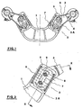
- FIG. 1 shows a support 1 that bears at each end a joint 2 for an arm 3 which comprises a clamp 4 adapted to clamp a sub-conductor not shown.
- Other parts of the joint are referred to by numbers shown in the following figures.
- FIG. 2 shows an end of the support 1, a rectangular outline frame 5, a core 6 having rectangular cross section positioned within the frame 5, four elastic elements 7 in the form of concave cylinders made of elastomer, each of them having one end glued onto the core and the other end glued onto a little plate 8 forced into a slot in the inner part of the frame 5, a branch 3A of the fork of an arm 3 (the other branch is not shown), the fork being rigidly fixed to the core 6 by means of two rivets 9, each passing through a hole in the core 6.
- the periphery of the core 6 is spaced from the inner perimeter of the frame 5 in order to allow the core itself to freely twist in the plane of the figure and in the planes perpendicular with the figure.
- FIG. 3 shows all the parts as indicated in the FIG. 2 and shows completely the fork of the arm 3 together with its two branches 3A, 3B.
- FIG. 3 also shows that the core 6 projects out of both the sides of the frame 5 in order to allow the arm 3 to freely twist in the plane of the figure together with the core 6.
- FIG. 4 shows a joint 2 comprising six elastic elements 10 made as steel spiral springs, conveniently fixed to little plates 8 forced into slots in the inner part of the frame 5 and to the core-6, the elastic elements being symmetrically spaced around the core itself.
- FIG. 5 shows a joint between the support 1 and an arm 3 .
- One of the two frames appears as sectioned, whereas the other one appears as a view.
- FIG. 6 shows a joint between the support 1 and an arm 3, the joint being composed by two frames 5, both of them being contained in a plane containing the support 1; the arm 3 forks at the bottom in two branches each being fixed to a core 6 elastically held in a relevant frame 5 by means of elastic elements 7, as it has been already described.
- the support 1, the frames 5, the cores 6, the little plates 8 and the arms 3 are of aluminium alloy.
- the frames of the joint 2 will be of any shape, circular, oval, polygonal, adapted to the purpose and that the support 1 will be of different shapes, each shape being suitable to the quantity of arms 3 that the support bears, depending on whether the conductor of the relevant electric line is a bundle made of two, three, four or more sub-conductors.
Landscapes
- Suspension Of Electric Lines Or Cables (AREA)
- Vibration Prevention Devices (AREA)
- Fluid-Damping Devices (AREA)
- Insulating Of Coils (AREA)
- Pens And Brushes (AREA)
- Prostheses (AREA)
- Communication Cables (AREA)
- Magnetic Heads (AREA)
- Housings And Mounting Of Transformers (AREA)
- Insulating Bodies (AREA)
- Coupling Device And Connection With Printed Circuit (AREA)
- Details Of Indoor Wiring (AREA)
- Springs (AREA)
- Shielding Devices Or Components To Electric Or Magnetic Fields (AREA)
Abstract
Description
- The invention relates to a spacer-damper for a bundled conductor of an electric line.
- In the bundled conductors of high and very high tension electric lines, namely in the conductors composed by two or more sub-conductors for each electric phase, it is required to keep correct the mutual spacing of the sub-conductors along each span between two subsequent towers as well as all along an electric line and also it is required to damp the movements of the single sub-conductors, substantially aeolian vibrations, namely vibrations having high frequency and small amplitudes caused by weak winds, and violent and large amplitude oscillations caused by strong winds.
- The spacer dampers are devices which are mounted on the electric lines in order to face both the above requirements and the applicant cites the single joint spacer-damper as disclosed through the Italian patent N° 936.310 filed by S.A.S. Officine Meccaniche Innocente Riganti di Innocente e Franco Riganti & C. of Solbiate Arno (Italy) and the multiple joint spacer-dampers produced by the Italian firms DAMP of Sovere and SALVI A.& C. of Milano.
- The main disadvantages of the known spacer-damper of the first cited manufacturer reside in that, due to the sole joint, each arm is allowed to make angular movements only, or on the other hand angular oscillations having their center in the joint center; in particular, there is no possibility of movements in the direction of the arm axis. The main disadvantages of the known spacer-dampers of the two other cited manufacturers reside in that they are allowed to make movements in numberless directions, but only in the plane perpendicular with the longitudinal axis of the sub-conductors. Moreover, in all the known devices as cited above the joint rigidity is nearly constant under aeolian vibrations so that the damping effect depends only on the hysteresis of the elastic means comprised in the joints and almost all the dissipated energy is transformed in heat which damages said elastic means. Furthermore, as in almost all the said devices the elastic means made of elastomer are compressed, it is cited a further disadvantage residing in that the performances of such devices vary remarkably depending on the external temperature.
- Finally, the prestress of said elastic means causes a high rigidity of the joints and, consequently, said devices are not sensitive to small exciting forces.
- The spacer-damper according to the invention, that will be referred to as device hereinafter,comprises a support on which as many arms for holding sub-conductors are articulated as sub-conductors in the relevant bundle of conductors there are, each joint between the support and an arm comprising:
- a frame integral with or fixed to the support and contained in a plane containing the support, a core positioned within the frame, a plurality of elastic elements each having one end fixed to the frame and the other end fixed to the core for keeping the.core itself elastically within the frame, the elastic elements being symmetrically spaced around the periphery of the core, an arm which bears on one end a clamp for clamping a sub-conductor and which is fixed by the other end to the core for the latter being allowed to move elastically within the frame under the actions that the relevant sub-conductor transmits to the arm, in any direction.
- According to a first alternative, each joint between the support and an arm comprises: one or more frames integral with or fixed to the support and contained in a plane which is anyhow inclined with respect to the support containing plane, a core positioned within each frame, a plurality of elastic elements for each frame, each elastic element having 'one end fixed to the corresponding frame and the other end fixed to the corresponding core for keeping the core itself elastically within the frame, the elastic elements for each frame being symmetrically located around the periphery of the core, an arm which bears on one end a clamp for clamping a sub-conductor and which bears on the opposite end means for fixing to each core for the latter being allowed to move elastically within the corresponding frame under the actions that the relevant sub-conductor transmits to the arm, in any direction.
- According to a second alternative, each joint between the support and an arm comprises: two or more frames integral with or fixed to the support and contained in plaines coincident with or parallel to a plane containing the support, a core positioned within each frame, a plurality of elastic elements for each frame, each elastic element having one end fixed to the corresponding frame and the other end fixed to the corresponding core for keeping the core itself elastically within the frame, the elastic elements for each frame being symmetrically located around the periphery of the core, an arm which bears on one end a clamp for clamping a sub-conductor and which bears on the opposite end means. for fixing to each core for the latter being allowed to move elastically within the corresponding frame under the actions that the relevant sub-conductor transmits to the arm, in any direction.
- The elastic elements are bodies made of elastomer or are steel springs, both of them being adapted to be compressed, extended, bent and twist under the actions transmitted from the sub-conductors through the arms.
- The fixing of the elastomer elastic elements to the core and the frame (or to small plates fastened to the frame) is made by gluing or by mechanical fastening means, like for instance by flange extensions in the ends of the elastic elements, conveniently engaged in corresponding recesses in the core and in the frame. Similarly, the fixing of the elastic elements consisting of steel springs is made by known mechanical fastening means or by welding.
- The main advantages of the invented device reside in that the arms are allowed to move in any direction and in any plane, without being engaged with fixed rotation centers; that the elastic characteristic of the joint is variable even for small transmitted movements; that the elastic elements are not subject to high overheating; that the damping effect is satisfactorily constant under ambient temperature variations; that the joint reacts to the twist movements of the arm with a remarkably low couple, so that remarkable bending of the sub-conductors is prevented in correspondence with the clamps when movements of the sub-conductors rise that twist the arms; that the elastic elements are working without sliding on any surface of the device so that there is no friction between said parts.
- Embodiments of the invented device are described herebelow, as an example only, with reference to the attached drawings wherein:
- FIG. 1 is an assembly view of a spacer-damper for twin conductor.
- FIG. 2 is a front view of a joint of the spacer-damper shown in FIG. 1.
- FIG. 3 is a cross section view, according to X-X of FIG. 2.
- FIG. 4 is a front view of a joint of the spacer-damper shown in FIG. 1 comprising an alternative in the elastic elements.
- FIG. 5 is a partly sectioned assembly view of half the spacer-damper for twin conductor according to a first alternative.
- FIG. 6 in an assembly view of half the spacer-damper for twin conductor according to a second alternative.
- FIG. 1 shows a
support 1 that bears at each end ajoint 2 for anarm 3 which comprises aclamp 4 adapted to clamp a sub-conductor not shown. Other parts of the joint are referred to by numbers shown in the following figures. - FIG. 2 shows an end of the
support 1, arectangular outline frame 5, acore 6 having rectangular cross section positioned within theframe 5, fourelastic elements 7 in the form of concave cylinders made of elastomer, each of them having one end glued onto the core and the other end glued onto alittle plate 8 forced into a slot in the inner part of theframe 5, a branch 3A of the fork of an arm 3 (the other branch is not shown), the fork being rigidly fixed to thecore 6 by means of tworivets 9, each passing through a hole in thecore 6. The periphery of thecore 6 is spaced from the inner perimeter of theframe 5 in order to allow the core itself to freely twist in the plane of the figure and in the planes perpendicular with the figure. - FIG. 3 shows all the parts as indicated in the FIG. 2 and shows completely the fork of the
arm 3 together with its two branches 3A, 3B. FIG. 3 also shows that thecore 6 projects out of both the sides of theframe 5 in order to allow thearm 3 to freely twist in the plane of the figure together with thecore 6. - FIG. 4 shows a
joint 2 comprising sixelastic elements 10 made as steel spiral springs, conveniently fixed tolittle plates 8 forced into slots in the inner part of theframe 5 and to the core-6, the elastic elements being symmetrically spaced around the core itself. - FIG. 5 shows a joint between the
support 1 and anarm 3 . composed by twoframes 5, each of them being comprised in a plane perpendicular'with a plane comprising thesupport 1; thearm 3 is fixed at the bottom to eachcore 6 comprised within aframe 5 and elastically held within said frame by means ofelastic elements 7, as it has been already described. One of the two frames appears as sectioned, whereas the other one appears as a view. - FIG. 6 shows a joint between the
support 1 and anarm 3, the joint being composed by twoframes 5, both of them being contained in a plane containing thesupport 1; thearm 3 forks at the bottom in two branches each being fixed to acore 6 elastically held in arelevant frame 5 by means ofelastic elements 7, as it has been already described. - The
support 1, theframes 5, thecores 6, thelittle plates 8 and thearms 3 are of aluminium alloy. - It will be realized that the frames of the
joint 2 will be of any shape, circular, oval, polygonal, adapted to the purpose and that thesupport 1 will be of different shapes, each shape being suitable to the quantity ofarms 3 that the support bears, depending on whether the conductor of the relevant electric line is a bundle made of two, three, four or more sub-conductors.
Claims (5)
Priority Applications (1)
| Application Number | Priority Date | Filing Date | Title |
|---|---|---|---|
| AT83108813T ATE59119T1 (en) | 1982-09-17 | 1983-09-07 | DAMPING SPACER FOR A BUNDLE CONDUCTOR OF A HIGH VOLTAGE LINE. |
Applications Claiming Priority (2)
| Application Number | Priority Date | Filing Date | Title |
|---|---|---|---|
| IT23315/82A IT1159093B (en) | 1982-09-17 | 1982-09-17 | DAMPER SPACER FOR ELECTRIC LINE BEAM CONDUCTORS |
| IT2331582 | 1982-09-17 |
Publications (3)
| Publication Number | Publication Date |
|---|---|
| EP0104514A2 true EP0104514A2 (en) | 1984-04-04 |
| EP0104514A3 EP0104514A3 (en) | 1987-03-25 |
| EP0104514B1 EP0104514B1 (en) | 1990-12-12 |
Family
ID=11205988
Family Applications (1)
| Application Number | Title | Priority Date | Filing Date |
|---|---|---|---|
| EP83108813A Expired - Lifetime EP0104514B1 (en) | 1982-09-17 | 1983-09-07 | Spacer-damper for a bundled conductor of an electric line |
Country Status (18)
| Country | Link |
|---|---|
| US (1) | US4533785A (en) |
| EP (1) | EP0104514B1 (en) |
| JP (1) | JPS5970115A (en) |
| KR (1) | KR840005939A (en) |
| AT (1) | ATE59119T1 (en) |
| AU (1) | AU557852B2 (en) |
| BR (1) | BR8305049A (en) |
| CA (1) | CA1202389A (en) |
| DE (1) | DE3382059D1 (en) |
| ES (1) | ES8500676A1 (en) |
| GR (1) | GR78996B (en) |
| HU (1) | HU186836B (en) |
| IN (1) | IN157537B (en) |
| IT (1) | IT1159093B (en) |
| MX (1) | MX153909A (en) |
| NZ (1) | NZ205165A (en) |
| YU (1) | YU185783A (en) |
| ZA (1) | ZA835164B (en) |
Cited By (2)
| Publication number | Priority date | Publication date | Assignee | Title |
|---|---|---|---|---|
| DE3610885A1 (en) * | 1986-04-02 | 1987-10-15 | Bergner Richard Gmbh Co | SELF-DAMPING FIELD SPACER FOR LEADER LADDER |
| EP0308692A3 (en) * | 1987-09-22 | 1990-02-14 | A. Salvi & C. S.p.a. | Damping spacer for bundle conductors of high voltage overhead electric lines with optic fibres cable inside the bundle |
Families Citing this family (5)
| Publication number | Priority date | Publication date | Assignee | Title |
|---|---|---|---|---|
| CA2274402A1 (en) | 1999-06-11 | 2000-12-11 | Hydro-Quebec | Damper for an overhead cable |
| US6316724B1 (en) | 2000-04-21 | 2001-11-13 | New Line Concepts, Llc | Utility line spacer and method for manufacturing same |
| CN103337823A (en) * | 2013-07-18 | 2013-10-02 | 国家电网公司 | All-insulated damping spacer for binary division sub-conductor |
| CN105207155B (en) * | 2015-10-16 | 2017-06-20 | 国网河南省电力公司电力科学研究院 | A kind of power transmission line spacer wire clamp attachment structure without rigid collision |
| DE102020200329B4 (en) * | 2020-01-13 | 2021-10-07 | Richard Bergner Holding GmbH & Co. KG | Field spacers |
Family Cites Families (8)
| Publication number | Priority date | Publication date | Assignee | Title |
|---|---|---|---|---|
| CH497803A (en) * | 1969-02-22 | 1970-10-15 | Salvi & Co Spa A | Elastic spacer for bundled conductors |
| US3617609A (en) * | 1970-11-19 | 1971-11-02 | Aluminum Co Of America | Conductor vibration damping device |
| NL7208464A (en) * | 1971-09-07 | 1973-03-09 | ||
| IT962511B (en) * | 1972-08-03 | 1973-12-31 | Cantamessa L | SPACER FOR BANDS OF CONDUCTORS FOR AERIAL POWER LINES |
| GB1495384A (en) * | 1973-12-13 | 1977-12-14 | Brush Switchgear | Spacer-dampers for power transmission lines |
| GB1507301A (en) * | 1974-03-12 | 1978-04-12 | Brush Switchgear | Spacer-damper for overhead power transmission lines |
| JPS5712559Y2 (en) * | 1975-07-10 | 1982-03-12 | ||
| JPS573297A (en) * | 1980-06-06 | 1982-01-08 | Japan Electronic Control Syst Co Ltd | Inspecting method for rom built in controller |
-
1982
- 1982-09-17 IT IT23315/82A patent/IT1159093B/en active
- 1982-12-17 IN IN1459/CAL/82A patent/IN157537B/en unknown
-
1983
- 1983-07-15 ZA ZA835164A patent/ZA835164B/en unknown
- 1983-08-05 GR GR72148A patent/GR78996B/el unknown
- 1983-08-05 NZ NZ205165A patent/NZ205165A/en unknown
- 1983-08-09 AU AU17804/83A patent/AU557852B2/en not_active Ceased
- 1983-08-16 ES ES524952A patent/ES8500676A1/en not_active Expired
- 1983-08-18 HU HU832909A patent/HU186836B/en unknown
- 1983-09-06 KR KR1019830004182A patent/KR840005939A/en not_active Withdrawn
- 1983-09-07 AT AT83108813T patent/ATE59119T1/en not_active IP Right Cessation
- 1983-09-07 DE DE8383108813T patent/DE3382059D1/en not_active Expired - Lifetime
- 1983-09-07 EP EP83108813A patent/EP0104514B1/en not_active Expired - Lifetime
- 1983-09-08 JP JP58164258A patent/JPS5970115A/en active Granted
- 1983-09-14 MX MX198707A patent/MX153909A/en unknown
- 1983-09-14 YU YU01857/83A patent/YU185783A/en unknown
- 1983-09-14 CA CA000436678A patent/CA1202389A/en not_active Expired
- 1983-09-16 BR BR8305049A patent/BR8305049A/en unknown
- 1983-09-19 US US06/533,536 patent/US4533785A/en not_active Expired - Fee Related
Cited By (2)
| Publication number | Priority date | Publication date | Assignee | Title |
|---|---|---|---|---|
| DE3610885A1 (en) * | 1986-04-02 | 1987-10-15 | Bergner Richard Gmbh Co | SELF-DAMPING FIELD SPACER FOR LEADER LADDER |
| EP0308692A3 (en) * | 1987-09-22 | 1990-02-14 | A. Salvi & C. S.p.a. | Damping spacer for bundle conductors of high voltage overhead electric lines with optic fibres cable inside the bundle |
Also Published As
| Publication number | Publication date |
|---|---|
| US4533785A (en) | 1985-08-06 |
| JPS5970115A (en) | 1984-04-20 |
| MX153909A (en) | 1987-02-18 |
| ES524952A0 (en) | 1984-11-01 |
| ATE59119T1 (en) | 1990-12-15 |
| AU557852B2 (en) | 1987-01-08 |
| KR840005939A (en) | 1984-11-19 |
| EP0104514A3 (en) | 1987-03-25 |
| GR78996B (en) | 1984-10-02 |
| IT8223315A0 (en) | 1982-09-17 |
| HU186836B (en) | 1985-09-30 |
| IT1159093B (en) | 1987-02-25 |
| EP0104514B1 (en) | 1990-12-12 |
| YU185783A (en) | 1986-02-28 |
| ES8500676A1 (en) | 1984-11-01 |
| NZ205165A (en) | 1987-05-29 |
| IN157537B (en) | 1986-04-19 |
| DE3382059D1 (en) | 1991-01-24 |
| BR8305049A (en) | 1984-05-08 |
| AU1780483A (en) | 1984-03-22 |
| IT8223315A1 (en) | 1984-03-17 |
| JPH0410290B2 (en) | 1992-02-24 |
| CA1202389A (en) | 1986-03-25 |
| ZA835164B (en) | 1984-04-25 |
Similar Documents
| Publication | Publication Date | Title |
|---|---|---|
| US5055971A (en) | Magnetic component using core clip arrangement operative for facilitating pick and place surface mount | |
| CA1121478A (en) | Rigid one-piece construction spacer damper with resiliently pivoted arms | |
| EP0104514A2 (en) | Spacer-damper for a bundled conductor of an electric line | |
| JPS58154346A (en) | Elastic suspension stator for synchronous generator | |
| US3925595A (en) | Frameless damping spacer | |
| US3940553A (en) | Frameless spacer with viscoelastic damping means | |
| US5732181A (en) | Fanout device for optical fibers of a multi-fiber cable | |
| US4012581A (en) | Frame-type damping spacer | |
| US4525596A (en) | Damping spacer for bundle conductors of high-voltage electric lines, with improved damping effectiveness | |
| KR930010355A (en) | Joint connection device of vehicle exhaust line member | |
| US3939300A (en) | Frameless damping spacer with close coil spring | |
| SU772506A3 (en) | Cross bar for splitter phase wires of overhead electric line | |
| RU1778847C (en) | Wire vibration-suppressor for power transmission lines | |
| US3454705A (en) | Spacer damper | |
| EP0308692A2 (en) | Damping spacer for bundle conductors of high voltage overhead electric lines with optic fibres cable inside the bundle | |
| RU2055246C1 (en) | Twisted rope vibration insulator | |
| SU1747758A1 (en) | Vibration isolator | |
| GB992196A (en) | Vibration-damping and load-supporting apparatus | |
| RU2084999C1 (en) | Section of aerial power line | |
| SU1710888A1 (en) | Shock absorber | |
| SU1696785A1 (en) | Vibration insulator | |
| RU1823057C (en) | Distance piece-damper of oscillation of wires of split phase of aerial power line | |
| SU894262A1 (en) | Shock absorber | |
| SU1010346A1 (en) | Shock-absorber | |
| JPH0123122Y2 (en) |
Legal Events
| Date | Code | Title | Description |
|---|---|---|---|
| PUAI | Public reference made under article 153(3) epc to a published international application that has entered the european phase |
Free format text: ORIGINAL CODE: 0009012 |
|
| AK | Designated contracting states |
Designated state(s): AT BE CH DE FR GB LI NL SE |
|
| 17P | Request for examination filed |
Effective date: 19840924 |
|
| PUAL | Search report despatched |
Free format text: ORIGINAL CODE: 0009013 |
|
| AK | Designated contracting states |
Kind code of ref document: A3 Designated state(s): AT BE CH DE FR GB LI NL SE |
|
| 17Q | First examination report despatched |
Effective date: 19880616 |
|
| RAP1 | Party data changed (applicant data changed or rights of an application transferred) |
Owner name: OFFICINA FRATELLI BERTOLOTTI S.P.A. |
|
| GRAA | (expected) grant |
Free format text: ORIGINAL CODE: 0009210 |
|
| AK | Designated contracting states |
Kind code of ref document: B1 Designated state(s): AT BE CH DE FR GB LI NL SE |
|
| REF | Corresponds to: |
Ref document number: 59119 Country of ref document: AT Date of ref document: 19901215 Kind code of ref document: T |
|
| REF | Corresponds to: |
Ref document number: 3382059 Country of ref document: DE Date of ref document: 19910124 |
|
| ET | Fr: translation filed | ||
| PLBE | No opposition filed within time limit |
Free format text: ORIGINAL CODE: 0009261 |
|
| STAA | Information on the status of an ep patent application or granted ep patent |
Free format text: STATUS: NO OPPOSITION FILED WITHIN TIME LIMIT |
|
| 26N | No opposition filed | ||
| EAL | Se: european patent in force in sweden |
Ref document number: 83108813.3 |
|
| PGFP | Annual fee paid to national office [announced via postgrant information from national office to epo] |
Ref country code: SE Payment date: 19950816 Year of fee payment: 13 |
|
| PGFP | Annual fee paid to national office [announced via postgrant information from national office to epo] |
Ref country code: CH Payment date: 19950821 Year of fee payment: 13 |
|
| PGFP | Annual fee paid to national office [announced via postgrant information from national office to epo] |
Ref country code: AT Payment date: 19950825 Year of fee payment: 13 |
|
| PGFP | Annual fee paid to national office [announced via postgrant information from national office to epo] |
Ref country code: GB Payment date: 19950829 Year of fee payment: 13 |
|
| PGFP | Annual fee paid to national office [announced via postgrant information from national office to epo] |
Ref country code: FR Payment date: 19950926 Year of fee payment: 13 |
|
| PGFP | Annual fee paid to national office [announced via postgrant information from national office to epo] |
Ref country code: NL Payment date: 19950929 Year of fee payment: 13 |
|
| PGFP | Annual fee paid to national office [announced via postgrant information from national office to epo] |
Ref country code: BE Payment date: 19951005 Year of fee payment: 13 |
|
| PGFP | Annual fee paid to national office [announced via postgrant information from national office to epo] |
Ref country code: DE Payment date: 19951120 Year of fee payment: 13 |
|
| PG25 | Lapsed in a contracting state [announced via postgrant information from national office to epo] |
Ref country code: GB Effective date: 19960907 Ref country code: AT Effective date: 19960907 |
|
| PG25 | Lapsed in a contracting state [announced via postgrant information from national office to epo] |
Ref country code: SE Effective date: 19960908 |
|
| PG25 | Lapsed in a contracting state [announced via postgrant information from national office to epo] |
Ref country code: LI Effective date: 19960930 Ref country code: FR Effective date: 19960930 Ref country code: CH Effective date: 19960930 Ref country code: BE Effective date: 19960930 |
|
| BERE | Be: lapsed |
Owner name: OFFICINA FRATELLI BERTOLOTTI S.P.A. Effective date: 19960930 |
|
| PG25 | Lapsed in a contracting state [announced via postgrant information from national office to epo] |
Ref country code: NL Effective date: 19970401 |
|
| GBPC | Gb: european patent ceased through non-payment of renewal fee |
Effective date: 19960907 |
|
| REG | Reference to a national code |
Ref country code: CH Ref legal event code: PL |
|
| NLV4 | Nl: lapsed or anulled due to non-payment of the annual fee |
Effective date: 19970401 |
|
| PG25 | Lapsed in a contracting state [announced via postgrant information from national office to epo] |
Ref country code: DE Effective date: 19970603 |
|
| EUG | Se: european patent has lapsed |
Ref document number: 83108813.3 |
|
| REG | Reference to a national code |
Ref country code: FR Ref legal event code: ST |
|
| REG | Reference to a national code |
Ref country code: FR Ref legal event code: ST |