EP0105232A1 - Strut suspension for an automotive vehicle - Google Patents
Strut suspension for an automotive vehicle Download PDFInfo
- Publication number
- EP0105232A1 EP0105232A1 EP83108995A EP83108995A EP0105232A1 EP 0105232 A1 EP0105232 A1 EP 0105232A1 EP 83108995 A EP83108995 A EP 83108995A EP 83108995 A EP83108995 A EP 83108995A EP 0105232 A1 EP0105232 A1 EP 0105232A1
- Authority
- EP
- European Patent Office
- Prior art keywords
- strut
- piston rod
- vibrations
- frequency
- suspension
- Prior art date
- Legal status (The legal status is an assumption and is not a legal conclusion. Google has not performed a legal analysis and makes no representation as to the accuracy of the status listed.)
- Granted
Links
- 239000000725 suspension Substances 0.000 title claims abstract description 45
- 238000013016 damping Methods 0.000 claims description 27
- 230000035939 shock Effects 0.000 claims description 24
- 239000006096 absorbing agent Substances 0.000 claims description 21
- 238000006073 displacement reaction Methods 0.000 claims description 11
- 240000005893 Pteridium aquilinum Species 0.000 claims 1
- 235000009936 Pteridium aquilinum Nutrition 0.000 claims 1
- 230000000694 effects Effects 0.000 abstract description 5
- 230000005540 biological transmission Effects 0.000 description 10
- 239000000428 dust Substances 0.000 description 7
- 230000013011 mating Effects 0.000 description 5
- 230000004048 modification Effects 0.000 description 5
- 238000012986 modification Methods 0.000 description 5
- 238000007789 sealing Methods 0.000 description 5
- 230000007935 neutral effect Effects 0.000 description 3
- 239000012212 insulator Substances 0.000 description 2
- XLYOFNOQVPJJNP-UHFFFAOYSA-N water Substances O XLYOFNOQVPJJNP-UHFFFAOYSA-N 0.000 description 2
- 230000006835 compression Effects 0.000 description 1
- 238000007906 compression Methods 0.000 description 1
- 238000010276 construction Methods 0.000 description 1
- 239000010687 lubricating oil Substances 0.000 description 1
- 230000000717 retained effect Effects 0.000 description 1
- 239000007787 solid Substances 0.000 description 1
- 230000003068 static effect Effects 0.000 description 1
Images


Classifications
-
- B—PERFORMING OPERATIONS; TRANSPORTING
- B60—VEHICLES IN GENERAL
- B60G—VEHICLE SUSPENSION ARRANGEMENTS
- B60G15/00—Resilient suspensions characterised by arrangement, location or type of combined spring and vibration damper, e.g. telescopic type
- B60G15/02—Resilient suspensions characterised by arrangement, location or type of combined spring and vibration damper, e.g. telescopic type having mechanical spring
- B60G15/06—Resilient suspensions characterised by arrangement, location or type of combined spring and vibration damper, e.g. telescopic type having mechanical spring and fluid damper
- B60G15/067—Resilient suspensions characterised by arrangement, location or type of combined spring and vibration damper, e.g. telescopic type having mechanical spring and fluid damper characterised by the mounting on the vehicle body or chassis of the spring and damper unit
- B60G15/068—Resilient suspensions characterised by arrangement, location or type of combined spring and vibration damper, e.g. telescopic type having mechanical spring and fluid damper characterised by the mounting on the vehicle body or chassis of the spring and damper unit specially adapted for MacPherson strut-type suspension
-
- B—PERFORMING OPERATIONS; TRANSPORTING
- B60—VEHICLES IN GENERAL
- B60G—VEHICLE SUSPENSION ARRANGEMENTS
- B60G15/00—Resilient suspensions characterised by arrangement, location or type of combined spring and vibration damper, e.g. telescopic type
- B60G15/02—Resilient suspensions characterised by arrangement, location or type of combined spring and vibration damper, e.g. telescopic type having mechanical spring
- B60G15/06—Resilient suspensions characterised by arrangement, location or type of combined spring and vibration damper, e.g. telescopic type having mechanical spring and fluid damper
- B60G15/062—Resilient suspensions characterised by arrangement, location or type of combined spring and vibration damper, e.g. telescopic type having mechanical spring and fluid damper the spring being arranged around the damper
- B60G15/066—Resilient suspensions characterised by arrangement, location or type of combined spring and vibration damper, e.g. telescopic type having mechanical spring and fluid damper the spring being arranged around the damper the spring being different from a coil spring
Definitions
- the present invention relates generally to a strut type suspension for an automotive vehicle, which is adapted to successfully prevent transmission of vibration or mechanical displacement between a wheel axle and a vehicle body. More specifically, the invention relates a strut-type suspension which can prevent transmission of not only relatively low-frequency vibrations but also relatively high-frequency vibration.
- a strut-type suspension absorbs relative displacements between a wheel axle and a vehicle body so as to prevent transmission of vibrations, road shocks and so forth.
- the strut suspension generally includes a shock absorber for damping relative displacements between the wheel axle and the vehicle body.
- the shock absorber will not work successfully and satisfactory for relatively small-amplitude, high-frequency mechanical vibrations of the wheel axle or the vehicle body.
- Such short-stroke vibrations are absorbed by an elastic damper inserted between a strut assembly and the vehicle body. If such an elastic damper is relatively hard, suspension will be relatively rigid and so produce a relatively higher damping force for absorbing short-stroke vibrations.
- Such a hard elastic damper is good for damping relatively low-frequency vibrations to provide good driving stability but will give a rough ride.
- such a hard elastic damper will not adequately eliminate relatively high-frequency vibrations.
- a relatively soft elastic damper when used, high-frequency vibrations will be successfully eliminated so that transmission of such high-frequency vibrations will be prevented.
- such a soft elastic damper will encounter a problem with respect to damping of relatively low-frequency vibrations which degrades driving stability and steering characteristics.
- an elastic damper such as a rubber . bushing is designed for damping not only relatively low-frequency vibrations but also relatively high-frequency vibrations, the size of the damper has to be so large as to make same unsuitable for the strut assembly. Furthermore, in the case of a relatively soft elastic damper, the damper will be worn out in a relatively short period of time due to the relatively large deformations caused by every displacement cycle.
- More specific object of the invention is to provide a strut-type suspension which includes an elastic damper for damping relatively short-stroke mechanical vibrations and which is effective both for relatively low-frequency vibrations and high-frequency vibrations.
- a strut-type suspension includes a pre-stressed spring member as a damper, which is adapted to prevent transmission of relatively high-frequency, low-amplitude vibrations.
- the pre-stressed spring is interposed between a suspension strut assembly and a vehicle body so as to absorb the relative displacement between the suspension strut and the vehicle body and so absorb the vibrations therebetween.
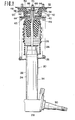
- a strut assembly 20 of the first embodiment of the invention comprises, in general, a cylindrical strut 22 and a shock absorber 24 with a piston rod 26.
- the lower end of the strut is connected to a knuckle 28 with a spindle 30 on which a wheel hub (not shown) can be mounted.
- the upper end of the piston rod 26 is secured to a strut house 32 of a vehicle body.
- the piston rod 26 is rigidly connected to a reciprocating piston (not shown) in a shock absorber cylinder 34 for axial movement according to relative displacement between a wheel axle (the spindle 30) and the vehicle body (strut house 32).
- a suspension coil spring 36 is wound around the strut 22 and seats onto a lower spring seat 38 rigidly secured to the outer periphery of the strut 22.
- the upper end of the suspension coil spring 36 is retained by an upper spring seat 40 which extends laterally from a damper - assembly 42.
- the damper assembly 42 generally includes a cylindrical bearing sleeve 44 extending around a stepped narrower-diameter section 46 of the piston rod 26.
- a pair of upper and lower brackets 48 and 50 respectively have central openings 52 and 54 through which the bearing sleeve 44 extends.
- a rubber damper 56 is interposed between the upper and lower brackets 48 and 50.
- the upper surface of the rubber damper 56 is rigidly secured onto the lower surface of the upper bracket 48 and the lower surface of the rubber damper 56 is rigidly secured onto the upper surface of the lower bracket 50.
- the rubber damper 56 is formed with a circumferentially extending groove 58.
- the lower bracket 50 has a flange 60 extending vertically from the circumferential edge of the central opening 54.
- a dish-shaped leaf spring 62 engages the inner circumference of the flange 60.
- the outer circumference of the leaf spring 62 engages a bent outer circumferential edge 64 of the upper spring seat 40.
- the central portion of the leaf spring 62 is biased upwards so that its inner circumferential edge lies at a level higher than its outer circumferential edge by an amount h.
- the height h is in the range of 1.2 to 1.5 times greater than the thickness t of the leaf spring 62 in its unloaded state.
- the leaf spring 62 when mounted in the damper assembly and the vehicle, is adapted to be pre-stressed by a static load applied by the weight of the - vehicle itself so that it is held nearly flat. This prestress is applied through the lower bracket 50 to which the vehicle weight is applied via the upper bracket 48 and the rubber damper 56.
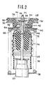
- the upper spring seat 40 has a substantially dish-shaped configuration, as best seen in Fig. 2, which defines a recess 65 which receives the inner portion of the leaf spring 62 when the latter is deformed downwardly.
- the bearing sleeve 44 is secured to the section 46 of the piston rod 26 by means of a washer 66 and a fastener nut 68 which is engageable with a threaded portion 70 of the piston rod 26.
- the washer 66 also serves as a retainer for restricting the upward displacement of tht- damper assembly relative to the piston rod 26 in the piston compression stroke.
- a dust cover 72 with an elastic bellows-shaped member 74 is secured to the lower end of the bearing sleeve 44 to protect the upper end of the strut 22 from muddy water, dust and so forth.
- the vibration is transferred to the strut assembly 20 via the wheel spindle 30 so that the strut 22 vibrates in accordance with the original vibration.
- the shock absorber cylinder 34 fixed . to the internal periphery of the strut 22 vibrates with the strut.
- This vibration of the strut is transmitted to the upper spring seat 40 via the lower spring seat 38 and the suspension coil spring 36, since the lower spring - seat 38 vibrates with the strut 22.
- the vibration of the upper spring seat 44 is transmitted to the leaf spring 62 and, in turn, to the rubber damper 56 via the lower bracket.
- the vibration of the upper bracket 48 is transmitted to the vehicle body via the strut house 32.
- the vibration applied to the shock absorber cylinder 34 is transmitted to the piston rod 26 via the piston in the shock absorber.
- the shock absorber 24 produces a damping force to absorb the vibration. Therefore, the lower magnitude vibration is applied to the damper assembly 42 via the piston rod 26. At the same time, a similar damping force is generated by the suspension coil spring for absorbing vibration energy so that a lower magnitude vibration is transmitted to the damper assembly. Due to the transmission of the lower magnitude vibration from the piston rod 26 and the suspension coil spring 36, the damper assembly 42 vibrates. The leaf spring 62 is then deformed from its neutral, substantially flat position, resulting in an additional damping force. Similarly, the rubber damper 56 is elastically deformed and its rebound force serves as yet another damping force. Thus, the vibration magnitude is further reduced by the damping effect of the leaf spring and the rubber damper.
- the shock absorber as an assembly of the shock absorber cylinder 34, the piston and the piston rod 26 may vibrate without performing any damping.
- the suspension coil spring may vibrate so as to transmit the vibration at an amplitude substantially as applied to the vehicle to the damper assembly 42 via the upper spring seat 44. Due to this vibration, the leaf spring 62 is again deformed from its neutral flat condition to produce a damping force to absorb the vibration energy. Vibrational energy is also absorbed by the rubber damper 56 which is deformed in response to the applied vibration to produce a damping force.
- the leaf spring 62 has a characteristic of deformation with respect to load in which the deformation rate is maximized at a point p which corresponds to the pre-loaded condition in which the central portion is deformed downward by an amount h so that the leaf spring is substantially flat.
- the rigidity of the leaf spring 62 increases non-linearly with the load so as to produce a greater damping force at greater loads. Therefore, the leaf spring 62 is relatively flexible around its neutral position so that it readily absorbs vibrational energy by deformation. This characteristic is suitable for absorbing short-stroke, high-frequency vibrations applied to the wheel while the vehicle is moving.
- This leaf spring 62 co-operates with the rubber damper to satisfactorily and successfully absorb vibrations.
- the effect of the shown embodiment is illustrated in Fig. 5 which shows experimentarily obtained values of overall strut vibration transmission with respect to vibration frequency.
- the phantom line represents vibration transmitted to the vehicle body by a conventional strut assembly having only a shock absorber, suspension coil spring and the rubber damper and the solid line represents vibration transmitted to the vehicle body via the shown embodiment of the strut assembly.
- vibration transmission via the strut assembly of the present invention is reduced by a significant amount. This improves riding comfort by reducing road noises and high-frequency vehicle body vibrations.
- the damping force to be created in response to substantially large-stroke shocks remains at a level sufficient to provide driving stability and cornering force.
- Fig. 6 shows the second embodiment of the strut-type automotive suspension according to the present invention.
- the piston rod 26 extending from the strut 22 engages a damper assembly 100.
- the damper assembly 100 includes upper and lower brackets 102 and 104 enclosing a rubber damper 106.
- the rubber damper 106 is formed with a circumferentially extending groove 107 for added flexibility.
- the lower bracket 104 is secured to the upper spring seat 40.
- the upper spring seat 40 is, in turn, rigidly secured to a bearing sleeve 108 which is secured to the narrow diameter section 46 of the piston rod 26 by means of a fastener nut 110 and the washer 112.
- a member 114 with an annular circumferential portion 116 and an upwardly recessed, cylindrical central portion 118 defining a rest 120 for receiving the end c' the piston rod 26 with the fastener nut 110, is rigidly secured onto the upper surface of the upper bracket 102.
- a fastener bolt 121 engages a threaded opening of the recessed central portion 118.
- the recessed central portion 118 also has a step 122 extending around its circular upper edge.
- the inner circumferential edge 124 of an annular dish-shaped leaf spring 126 is mounted on the step 122 of the member 114 via a ring of piano wire 128.
- the outer circumferential edge 130 of the leaf spring 126 engages a circumferentially extending step 132 formed in a bracket 134 from which fastener bolts extend upwardly to engage the strut house of the vehicle body.
- a ring of piano wire 128 is also inserted between the outer circumferential edge 130 of the leaf spring 126 and the mating surface 136 of the step 132 of the bracket 134.
- the piano wires 128 are provided to reduce the mechanical friction between the leaf spring 126 and the mating surfaces. As shown in Fig.
- each piano wire 128 has a pair of elastic sealing lips 138 and 140 extending from its opposite coplanar edges.
- the free edges of the sealing lips 138 are adapted to contact the corresponding edges of the leaf spring 126 and the free edges of the sealing lips 140 are adapted to contact the mating surface of the step 122 or 132.
- the sealing lips 138 and 140 and the piano wire 128 establish sealing contact with their mating surfaces in order to retain lubricating oil in the spaces 142 defined between the brackets 134 and 114 and the leaf spring 126.
- the suspension coil spring 36 is wound around the strut 22 and seated to the upper and lower spring seats 40 and 38.
- the dust cover 72 with the elastic bellows-shaped member 74 is secured to the lower end of the bearing sleeve in order to protect the upper end portion of the strut from muddy water, dust and so forth.
- Rubber insulator 41 is secured to the lower surface of the dust cover 72 and surrounds the piston rod. The rubber insulator serves as a damper for preventing the top of the strut from colliding with the dust cover.
- relatively large-amplitude vibrations from the road wheel are absorbed - by the shock absorber in the strut and the suspension coil spring.
- relatively low-amplitude, high-frequency vibrations from the road wheel are transmitted to the damper assembly 100 via the strut 22, the suspension coil spring 36 and the upper spring seat 40.
- the vibration 'energy of the relatively high-frequency, low-amplitude vibrations is first absorbed by the rubber damper 106 due to deformation of the latter.
- the vibration energy is further absorbed by the leaf spring 126 due to deformation of the latter in accordance with the applied vibration.
- the leaf spring 126 is pre-loaded to be held substantially flat.
- the leaf spring 126 has the same damping characteristics as illustrated in Fig. 4, by which deformation magnitude increases in accordance with increases in load.
- a shock absorbing effect similar to that achieved by the foregoing first embodiment can be provided by the shown second embodiment.
- Figs. 8 to 11 show a modification of the foregoing second embodiment of the strut-type suspension.
- the leaf spring 126 is formed with cutouts 150 and 152 in its inner and outer circumferential edges respectively.
- the cutout 150 on the inner circumferential edge of the leaf spring 126 is engageable with a positioning pin 154 protruding from the central portion 118 of the member 114.
- the cutout 152 on the outer circumferential edge of the leaf spring 126 is engageable with a positioning pin 156 - protruding from the bracket 134. Due to engagement of the cutouts and the positioning pins, the member 114, the bracket 134 and the leaf spring 126 are held in a specific angular relationship with respect to one another.
- the bracket has fastener bolts 158 extending therefrom which rigidly secure the strut assembly to the strut house of the vehicle body.
- the specific angular relationship between the member 114, the bracket 134 and the leaf spring 126 serves to position the fastener bolts 158 in alignment with the through openings in order to facilitate engagement of the fastener bolts 158 with the through openings (not shown) in the strut house.
- the piano wires 128 inserted between the circumferential edges of the leaf spring and the mating surfaces of the member 114 and the bracket 134 are cut at point corresponding to the cutouts 150 and 152 respectively to allow cutout-and-pin engagement, as shown in Figs. 10 and 11.
- the arrangement of the cutout and the positioning pin for positioning the bracket 134 with respect to the leaf spring 126 and the member 114 can be modified in various ways.
- the positioning pin can be replaced with a key-projecting from the bracket and the member 114 at points corresponding to the cutouts.
- the cutout may be formed in the bracket 134 and the member 114 with the positioning pins or keys provided in the leaf spring.
- the third embodiment of the strut-type suspension includes a pillow block assembly 202 in a damper assembly 200.
- a pillow ball 204 in the pillow block assembly 202 is attached to the piston rod 26 of the shock absorber extending from the strut.
- the pillow ball 204 is axially positioned along the piston rod 26 by means of bearing sleeves 206 and 208, a washer 210 and fastener nut 212 which engages a threaded end 214 of the piston rod 26.
- a pillow block 216 rotatably engages the pillow ball.
- the pillow block 216 has a lateral extension which includes a portion 218 serving as an upper spring seat for the suspension coil spring 36.
- An inwardly bent flange portion 220 extends from the upper spring seat portion 218 via vertical portion 222.
- a member 224 with an annular outer circumferential portion 226 and an upwardly recessed, cylindrical, central portion 228 is secured to the flange portion 220 of the pillow block 216 by fastener bolts 230-, at the circumferential portion 226.
- the member 224 is attached to a bracket 232 from which fastener bolts for securing the strut assembly to the strut house of the vehicle body extend, by means of a connector bolt 234 engageable with a threaded opening 236 in the central portion 228.
- the connector bolt 234 has a rectangular head 238.
- the bracket 232 has a rectangular opening 240 through which the connector bolt 234 engages the threaded opening 236.
- the connector bolt 234 is screwed into the threaded opening 236 prior to attaching the bracket 232 to the member 224.
- the rectangular opening 240. is of a size corresponding to the rectangular head 238 of the connector bolt 234 to allow the latter to pass therethrough. Thereafter, either the bracket or the member 234 is rotated relative to the other the aling the longer axis of the rectangular head 238 perpendicular to the longer axis of the rectangular opening. In this way, the bracket and the member 234 are secured to one another.
- vibrations from the road wheel are transmitted to the strut and to the suspension coil spring.
- the vibration of the piston of the shock absorber is then transmitted to the pillow block 216 via the piston rod 26.
- the vibration of the strut is also transmitted to the pillow block 216 via the suspension coil spring 36.
- the vibration is damped by the shock absorber and the suspension coil spring.
- a leaf spring 242 becomes effective to absorb the vibration as in the foregoing first and second embodiments.
- the pillow block assembly 20 2 effectively absorbs rotational or swinging - movement of the suspension strut so that riding comfort is ensured even when the strut assembly sways.
Landscapes
- Engineering & Computer Science (AREA)
- Mechanical Engineering (AREA)
- Vehicle Body Suspensions (AREA)
Abstract
Description
- The present invention relates generally to a strut type suspension for an automotive vehicle, which is adapted to successfully prevent transmission of vibration or mechanical displacement between a wheel axle and a vehicle body. More specifically, the invention relates a strut-type suspension which can prevent transmission of not only relatively low-frequency vibrations but also relatively high-frequency vibration.
- In general, a strut-type suspension absorbs relative displacements between a wheel axle and a vehicle body so as to prevent transmission of vibrations, road shocks and so forth. The strut suspension generally includes a shock absorber for damping relative displacements between the wheel axle and the vehicle body. However, the shock absorber will not work successfully and satisfactory for relatively small-amplitude, high-frequency mechanical vibrations of the wheel axle or the vehicle body. Such short-stroke vibrations are absorbed by an elastic damper inserted between a strut assembly and the vehicle body. If such an elastic damper is relatively hard, suspension will be relatively rigid and so produce a relatively higher damping force for absorbing short-stroke vibrations. Such a hard elastic damper is good for damping relatively low-frequency vibrations to provide good driving stability but will give a rough ride. In addition, such a hard elastic damper will not adequately eliminate relatively high-frequency vibrations. In turn, when a relatively soft elastic damper is used, high-frequency vibrations will be successfully eliminated so that transmission of such high-frequency vibrations will be prevented. However, such a soft elastic damper will encounter a problem with respect to damping of relatively low-frequency vibrations which degrades driving stability and steering characteristics.
- If an elastic damper such as a rubber.bushing is designed for damping not only relatively low-frequency vibrations but also relatively high-frequency vibrations, the size of the damper has to be so large as to make same unsuitable for the strut assembly. Furthermore, in the case of a relatively soft elastic damper, the damper will be worn out in a relatively short period of time due to the relatively large deformations caused by every displacement cycle.
- Therefore, in the prior art, it has been impossible, in practice, to achieve a damping effect sufficient to successfully and satisfactorily prevent transmission of vibrations due to mechanical displacements between the wheel axle and the vehicle body.
- Therefore, it is an object of the present invention to provide a strut-type suspension which can successfully prevent transmission not only of relatively low-freauency vibrations but also of relatively high-frequency vibrations.
- More specific object of the invention is to provide a strut-type suspension which includes an elastic damper for damping relatively short-stroke mechanical vibrations and which is effective both for relatively low-frequency vibrations and high-frequency vibrations.
- To accomplish the foregoing and other objects, a strut-type suspension, according to the present invention, includes a pre-stressed spring member as a damper, which is adapted to prevent transmission of relatively high-frequency, low-amplitude vibrations. The pre-stressed spring is interposed between a suspension strut assembly and a vehicle body so as to absorb the relative displacement between the suspension strut and the vehicle body and so absorb the vibrations therebetween.
- . The present invention will be understood more fully from the detailed description give herebelow and from the accompanying drawings of the preferred embodiments of the invention, which, however, should not be taken to limit - the invention but are for explanation only.
- In the drawings:
- Fig. 1 shows a section of the first embodiment of strut assembly according to the present invention;
- Fig. 2 is an enlarged view of the strut assembly of Fig. 1, showing the structure thereof in more detail;
- Fig. 3 is a cross-sectional view of a leaf spring employed in the strut assembly of Fig. 1, shown in the unloaded condition;
- Fig. 4 shows the deformation characteristics of the leaf spring of Fig. 3 in terms of load applied thereto;
- Fig. 5 shows the variation of vibration in relation to load, in which the solid curve represents the vibration variation in the strut assembly of Fig. 1 and the phantom curve represents the vibration variation in a typical conventional strut assembly;
- Fig. 6 is a view similar to Fig. 2 of the second embodiment of the strut assembly according to the present invention;
- Fig. 7 is an enlarged cross-sectional view of a piano wire used in the strut assembly of Fig. 6;
- Fig. 8 is a cross-sectional view of a modification of the second embodiment of strut assembly;
- Fig. 9 is a plan view of the leaf spring used in the modification of Fig. 8;
- Fig. 10 shows a section taken along line X-X of Fig. 8;
- Fig. 11 shows a section taken along line XI-XI of Fig. 8;
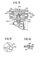
- Fig. 12 shows a section of the major part of the third embodiment of the strut assembly according to the present invention;
- Fig. 13 is a plan view of a bracket in the third embodiment of Fig. 12; and
- Fig. 14 shows a fragmentary section of the bracket of Fig. 13 as engaged with a connector bolt.
- Referring now to the drawings, particularly to Figs. 1 and 2, a
strut assembly 20 of the first embodiment of the invention comprises, in general, acylindrical strut 22 and a shock absorber 24 with apiston rod 26. The lower end of the strut is connected to aknuckle 28 with aspindle 30 on which a wheel hub (not shown) can be mounted. On the other hand, the upper end of thepiston rod 26 is secured to astrut house 32 of a vehicle body. Thepiston rod 26 is rigidly connected to a reciprocating piston (not shown) in ashock absorber cylinder 34 for axial movement according to relative displacement between a wheel axle (the spindle 30) and the vehicle body (strut house 32). - A
suspension coil spring 36 is wound around thestrut 22 and seats onto alower spring seat 38 rigidly secured to the outer periphery of thestrut 22. The upper end of thesuspension coil spring 36 is retained by anupper spring seat 40 which extends laterally from a damper -assembly 42. - The
damper assembly 42 generally includes acylindrical bearing sleeve 44 extending around a stepped narrower-diameter section 46 of thepiston rod 26. A pair of upper andlower brackets central openings bearing sleeve 44 extends. - Arubber damper 56 is interposed between the upper andlower brackets rubber damper 56 is rigidly secured onto the lower surface of theupper bracket 48 and the lower surface of therubber damper 56 is rigidly secured onto the upper surface of thelower bracket 50. Therubber damper 56 is formed with a circumferentially extendinggroove 58. - The
lower bracket 50 has a flange 60 extending vertically from the circumferential edge of thecentral opening 54. A dish-shaped leaf spring 62 engages the inner circumference of the flange 60. The outer circumference of theleaf spring 62 engages a bent outercircumferential edge 64 of theupper spring seat 40. As shown in Fig. 3, the central portion of theleaf spring 62 is biased upwards so that its inner circumferential edge lies at a level higher than its outer circumferential edge by an amount h. In practice, the height h is in the range of 1.2 to 1.5 times greater than the thickness t of theleaf spring 62 in its unloaded state. Theleaf spring 62, when mounted in the damper assembly and the vehicle, is adapted to be pre-stressed by a static load applied by the weight of the - vehicle itself so that it is held nearly flat. This prestress is applied through thelower bracket 50 to which the vehicle weight is applied via theupper bracket 48 and therubber damper 56. - The
upper spring seat 40 has a substantially dish-shaped configuration, as best seen in Fig. 2, which defines arecess 65 which receives the inner portion of theleaf spring 62 when the latter is deformed downwardly. - The
bearing sleeve 44 is secured to thesection 46 of thepiston rod 26 by means of awasher 66 and afastener nut 68 which is engageable with a threadedportion 70 of thepiston rod 26. Thewasher 66 also serves as a retainer for restricting the upward displacement of tht- damper assembly relative to thepiston rod 26 in the piston compression stroke. Adust cover 72 with an elastic bellows-shaped member 74 is secured to the lower end of thebearing sleeve 44 to protect the upper end of thestrut 22 from muddy water, dust and so forth. - When a vibration such as road shock is applied to the vehicle wheel, the vibration is transferred to the
strut assembly 20 via thewheel spindle 30 so that thestrut 22 vibrates in accordance with the original vibration. At the same time, the shock absorbercylinder 34 fixed.to the internal periphery of thestrut 22 vibrates with the strut. This vibration of the strut is transmitted to theupper spring seat 40 via thelower spring seat 38 and thesuspension coil spring 36, since the lower spring -seat 38 vibrates with thestrut 22. The vibration of theupper spring seat 44 is transmitted to theleaf spring 62 and, in turn, to therubber damper 56 via the lower bracket. Then, the vibration of theupper bracket 48 is transmitted to the vehicle body via thestrut house 32. - On the other hand, the vibration applied to the
shock absorber cylinder 34 is transmitted to thepiston rod 26 via the piston in the shock absorber. - When magnitude of the vibration is relatively large, so that the
washer 66 comes into contact with theupper bracket 48 or thedust cover 72 comes into contact with theupper spring seat 44, theshock absorber 24 produces a damping force to absorb the vibration. Therefore, the lower magnitude vibration is applied to thedamper assembly 42 via thepiston rod 26. At the same time, a similar damping force is generated by the suspension coil spring for absorbing vibration energy so that a lower magnitude vibration is transmitted to the damper assembly. Due to the transmission of the lower magnitude vibration from thepiston rod 26 and thesuspension coil spring 36, thedamper assembly 42 vibrates. Theleaf spring 62 is then deformed from its neutral, substantially flat position, resulting in an additional damping force. Similarly, therubber damper 56 is elastically deformed and its rebound force serves as yet another damping force. Thus, the vibration magnitude is further reduced by the damping effect of the leaf spring and the rubber damper. - If the vibration applied is of substantially low amplitude so that the
shock absorber 24 and thesuspension coil spring 36 produce essentially no damping force, the shock absorber as an assembly of theshock absorber cylinder 34, the piston and thepiston rod 26 may vibrate without performing any damping. Similarly, the suspension coil spring may vibrate so as to transmit the vibration at an amplitude substantially as applied to the vehicle to thedamper assembly 42 via theupper spring seat 44. Due to this vibration, theleaf spring 62 is again deformed from its neutral flat condition to produce a damping force to absorb the vibration energy. Vibrational energy is also absorbed by therubber damper 56 which is deformed in response to the applied vibration to produce a damping force. - As shown in Fig. 4, the
leaf spring 62 has a characteristic of deformation with respect to load in which the deformation rate is maximized at a point p which corresponds to the pre-loaded condition in which the central portion is deformed downward by an amount h so that the leaf spring is substantially flat. As can be appreciated from Fig. 4, the rigidity of theleaf spring 62 increases non-linearly with the load so as to produce a greater damping force at greater loads. Therefore, theleaf spring 62 is relatively flexible around its neutral position so that it readily absorbs vibrational energy by deformation. This characteristic is suitable for absorbing short-stroke, high-frequency vibrations applied to the wheel while the vehicle is moving. - This
leaf spring 62 co-operates with the rubber damper to satisfactorily and successfully absorb vibrations. The effect of the shown embodiment is illustrated in Fig. 5 which shows experimentarily obtained values of overall strut vibration transmission with respect to vibration frequency. In Fig. 5, the phantom line represents vibration transmitted to the vehicle body by a conventional strut assembly having only a shock absorber, suspension coil spring and the rubber damper and the solid line represents vibration transmitted to the vehicle body via the shown embodiment of the strut assembly. As will be apparent herefrom vibration transmission via the strut assembly of the present invention is reduced by a significant amount. This improves riding comfort by reducing road noises and high-frequency vehicle body vibrations. Furthermore, according to the shown arrangement, the damping force to be created in response to substantially large-stroke shocks remains at a level sufficient to provide driving stability and cornering force. - Fig. 6 shows the second embodiment of the strut-type automotive suspension according to the present invention. In this embodiment, the
piston rod 26 extending from thestrut 22 engages adamper assembly 100. As in the - foregoing first embodiment, thedamper assembly 100 includes upper andlower brackets rubber damper 106. Therubber damper 106 is formed with acircumferentially extending groove 107 for added flexibility. Thelower bracket 104 is secured to theupper spring seat 40. Theupper spring seat 40 is, in turn, rigidly secured to abearing sleeve 108 which is secured to thenarrow diameter section 46 of thepiston rod 26 by means of a fastener nut 110 and thewasher 112. - A
member 114, with an annularcircumferential portion 116 and an upwardly recessed, cylindricalcentral portion 118 defining arest 120 for receiving the end c' thepiston rod 26 with the fastener nut 110, is rigidly secured onto the upper surface of theupper bracket 102. Afastener bolt 121 engages a threaded opening of the recessedcentral portion 118. The recessedcentral portion 118 also has astep 122 extending around its circular upper edge. - The inner
circumferential edge 124 of an annular dish-shapedleaf spring 126 is mounted on thestep 122 of themember 114 via a ring ofpiano wire 128. The outercircumferential edge 130 of theleaf spring 126 engages acircumferentially extending step 132 formed in abracket 134 from which fastener bolts extend upwardly to engage the strut house of the vehicle body. A ring ofpiano wire 128 is also inserted between the outercircumferential edge 130 of theleaf spring 126 and themating surface 136 of thestep 132 of thebracket 134. Thepiano wires 128 are provided to reduce the mechanical friction between theleaf spring 126 and the mating surfaces. As shown in Fig. 7, eachpiano wire 128 has a pair of elastic sealinglips lips 138 are adapted to contact the corresponding edges of theleaf spring 126 and the free edges of the sealinglips 140 are adapted to contact the mating surface of thestep lips piano wire 128 establish sealing contact with their mating surfaces in order to retain lubricating oil in thespaces 142 defined between thebrackets leaf spring 126. - As in the foregoing first embodiment, the
suspension coil spring 36 is wound around thestrut 22 and seated to the upper andlower spring seats dust cover 72 with the elastic bellows-shapedmember 74 is secured to the lower end of the bearing sleeve in order to protect the upper end portion of the strut from muddy water, dust and so forth.Rubber insulator 41 is secured to the lower surface of thedust cover 72 and surrounds the piston rod. The rubber insulator serves as a damper for preventing the top of the strut from colliding with the dust cover. - As in the foregoing first embodiment, relatively large-amplitude vibrations from the road wheel are absorbed - by the shock absorber in the strut and the suspension coil spring. On the other hand, relatively low-amplitude, high-frequency vibrations from the road wheel are transmitted to the
damper assembly 100 via thestrut 22, thesuspension coil spring 36 and theupper spring seat 40. The vibration 'energy of the relatively high-frequency, low-amplitude vibrations is first absorbed by therubber damper 106 due to deformation of the latter. The vibration energy is further absorbed by theleaf spring 126 due to deformation of the latter in accordance with the applied vibration. - The
leaf spring 126 is pre-loaded to be held substantially flat. Theleaf spring 126 has the same damping characteristics as illustrated in Fig. 4, by which deformation magnitude increases in accordance with increases in load. Thus, a shock absorbing effect similar to that achieved by the foregoing first embodiment can be provided by the shown second embodiment. - Figs. 8 to 11 show a modification of the foregoing second embodiment of the strut-type suspension. In this modification, the
leaf spring 126 is formed withcutouts cutout 150 on the inner circumferential edge of theleaf spring 126 is engageable with apositioning pin 154 protruding from thecentral portion 118 of themember 114. On the other hand, thecutout 152 on the outer circumferential edge of theleaf spring 126 is engageable with a positioning pin 156 - protruding from thebracket 134. Due to engagement of the cutouts and the positioning pins, themember 114, thebracket 134 and theleaf spring 126 are held in a specific angular relationship with respect to one another. - As set forth previously, the bracket has
fastener bolts 158 extending therefrom which rigidly secure the strut assembly to the strut house of the vehicle body. The specific angular relationship between themember 114, thebracket 134 and theleaf spring 126 serves to position thefastener bolts 158 in alignment with the through openings in order to facilitate engagement of thefastener bolts 158 with the through openings (not shown) in the strut house. - In this modification, the
piano wires 128 inserted between the circumferential edges of the leaf spring and the mating surfaces of themember 114 and thebracket 134 are cut at point corresponding to thecutouts - It will be appreciated that the arrangement of the cutout and the positioning pin for positioning the
bracket 134 with respect to theleaf spring 126 and themember 114 can be modified in various ways. For example, the positioning pin can be replaced with a key-projecting from the bracket and themember 114 at points corresponding to the cutouts. In another example, the cutout may be formed in thebracket 134 and themember 114 with the positioning pins or keys provided in the leaf spring. - Referring to Fig. 12, the third embodiment of the strut-type suspension includes a
pillow block assembly 202 in adamper assembly 200. Apillow ball 204 in thepillow block assembly 202 is attached to thepiston rod 26 of the shock absorber extending from the strut. Thepillow ball 204 is axially positioned along thepiston rod 26 by means of bearingsleeves washer 210 andfastener nut 212 which engages a threadedend 214 of thepiston rod 26. Apillow block 216 rotatably engages the pillow ball. Thepillow block 216 has a lateral extension which includes aportion 218 serving as an upper spring seat for thesuspension coil spring 36. An inwardlybent flange portion 220 extends from the upperspring seat portion 218 viavertical portion 222. Amember 224 with an annular outercircumferential portion 226 and an upwardly recessed, cylindrical,central portion 228 is secured to theflange portion 220 of thepillow block 216 by fastener bolts 230-, at thecircumferential portion 226. Themember 224 is attached to abracket 232 from which fastener bolts for securing the strut assembly to the strut house of the vehicle body extend, by means of aconnector bolt 234 engageable with a threadedopening 236 in thecentral portion 228. - . As shown in Figs. 13 and 14, the
connector bolt 234 has arectangular head 238. Thebracket 232 has arectangular opening 240 through which theconnector bolt 234 engages the threadedopening 236. Theconnector bolt 234 is screwed into the threadedopening 236 prior to attaching thebracket 232 to themember 224. Therectangular opening 240. is of a size corresponding to therectangular head 238 of theconnector bolt 234 to allow the latter to pass therethrough. Thereafter, either the bracket or themember 234 is rotated relative to the other the aling the longer axis of therectangular head 238 perpendicular to the longer axis of the rectangular opening. In this way, the bracket and themember 234 are secured to one another. - In this structure of the third embodiment, vibrations from the road wheel are transmitted to the strut and to the suspension coil spring. The vibration of the piston of the shock absorber is then transmitted to the
pillow block 216 via thepiston rod 26. In turn, the vibration of the strut is also transmitted to thepillow block 216 via thesuspension coil spring 36. - When the magnitude of vibration is large enough for the shock absorber and the
suspension coil spring 36 to produce a damping force, the vibration is damped by the shock absorber and the suspension coil spring. On the other hand, if the magnitude of vibration is relatively small and the frequency thereof is relatively high, aleaf spring 242 becomes effective to absorb the vibration as in the foregoing first and second embodiments. Furthermore, in this construction, thepillow block assembly 202 effectively absorbs rotational or swinging - movement of the suspension strut so that riding comfort is ensured even when the strut assembly sways. - Thus, as set forth above, according to the present invention, relatively high-frequency, low-amplitude vibrations which cause road noise and so forth can be successfully and satisfactorily absorbed by the leaf spring provided in the strut assembly.
Claims (13)
Applications Claiming Priority (4)
| Application Number | Priority Date | Filing Date | Title |
|---|---|---|---|
| JP16057482A JPS5950803A (en) | 1982-09-14 | 1982-09-14 | Wheel suspension device |
| JP160574/82 | 1982-09-14 | ||
| JP12222/83 | 1983-01-31 | ||
| JP1222283U JPS59117508U (en) | 1983-01-31 | 1983-01-31 | wheel suspension system |
Publications (2)
| Publication Number | Publication Date |
|---|---|
| EP0105232A1 true EP0105232A1 (en) | 1984-04-11 |
| EP0105232B1 EP0105232B1 (en) | 1986-12-10 |
Family
ID=26347792
Family Applications (1)
| Application Number | Title | Priority Date | Filing Date |
|---|---|---|---|
| EP83108995A Expired EP0105232B1 (en) | 1982-09-14 | 1983-09-12 | Strut suspension for an automotive vehicle |
Country Status (3)
| Country | Link |
|---|---|
| US (1) | US4568067A (en) |
| EP (1) | EP0105232B1 (en) |
| DE (1) | DE3368235D1 (en) |
Cited By (3)
| Publication number | Priority date | Publication date | Assignee | Title |
|---|---|---|---|---|
| DE3903143A1 (en) * | 1988-02-02 | 1989-08-10 | Nissan Motor | FRONT SUSPENSION FOR MOTOR VEHICLES WITH FRONT ENGINE |
| WO2011006863A1 (en) * | 2009-07-15 | 2011-01-20 | Bayerische Motoren Werke Aktiengesellschaft | Motor vehicle having at least one receptacle for connectig a damper |
| WO2015090626A1 (en) * | 2013-12-19 | 2015-06-25 | Bayerische Motoren Werke Aktiengesellschaft | Vibration damper support or suspension strut support for a motor vehicle wheel suspension |
Families Citing this family (32)
| Publication number | Priority date | Publication date | Assignee | Title |
|---|---|---|---|---|
| JPS6060024A (en) * | 1983-09-09 | 1985-04-06 | Nissan Motor Co Ltd | Roll rigidity controller in vehicle |
| US4770438A (en) * | 1984-01-20 | 1988-09-13 | Nissan Motor Co., Ltd. | Automotive suspension control system with road-condition-dependent damping characteristics |
| JPS6164506A (en) * | 1984-09-05 | 1986-04-02 | Nissan Motor Co Ltd | Strut type suspension |
| US4771996A (en) * | 1987-03-26 | 1988-09-20 | Maremont Corporation | MacPherson strut with floating striker plate |
| US4969542A (en) * | 1989-07-17 | 1990-11-13 | General Motors Corporation | Dust shield for a damper |
| DE3939650A1 (en) * | 1989-11-30 | 1991-06-06 | Daimler Benz Ag | HYDRAULIC DAMPER ARRANGEMENT |
| JP2720638B2 (en) * | 1991-06-24 | 1998-03-04 | 日産自動車株式会社 | Vehicle suspension mounting device |
| US5263694A (en) * | 1992-02-24 | 1993-11-23 | General Motors Corporation | Upper mount assembly for a suspension damper |
| WO1993019973A1 (en) * | 1992-04-07 | 1993-10-14 | Ab Volvo | Shock absorbing and sprung suspension system |
| US5362035A (en) * | 1993-09-30 | 1994-11-08 | Chrysler Corporation | Tunable front suspension strut mount |
| US5492314A (en) * | 1995-03-03 | 1996-02-20 | General Motors Corporation | Preloaded digressive rate mount |
| JP3205480B2 (en) * | 1995-03-23 | 2001-09-04 | 東海ゴム工業株式会社 | Suspension device |
| DE19723347C1 (en) * | 1997-06-04 | 1998-12-17 | Mannesmann Sachs Ag | Sprung suspension strut for motor vehicle |
| US6199844B1 (en) | 1998-07-27 | 2001-03-13 | Chrysler Corporation | Striker cap for vehicle suspension system |
| US6079700A (en) * | 1998-10-09 | 2000-06-27 | Chrysler Corporation | Vehicle shock absorber spring seat pad having a spring--containment peripheral flange |
| US6186486B1 (en) | 1999-07-30 | 2001-02-13 | Delphi Technologies, Inc. | Jounce bumper plate |
| US6408970B1 (en) * | 2000-08-28 | 2002-06-25 | Allen L. Eng | Cab suspension system for terminal tractors |
| US6616160B2 (en) * | 2001-04-05 | 2003-09-09 | Toyo Tire & Rubber Co., Ltd. | Strut mount |
| FR2863329B1 (en) * | 2003-12-09 | 2007-08-17 | Hutchinson | SUSPENSION SUPPORT DEVICE AND VEHICLE COMPRISING SUCH A DEVICE |
| TWD112713S1 (en) * | 2004-08-09 | 2006-09-01 | 仁不古股份有限公司 | Hydraulic Buffer |
| US7328887B2 (en) * | 2005-04-01 | 2008-02-12 | Bfs Diversified Products, Llc | Self-indexing spacer for air spring assembly |
| US8333269B2 (en) * | 2006-07-17 | 2012-12-18 | Basf Corporation | Insulator for a wheel suspension system |
| US8574483B2 (en) | 2006-07-17 | 2013-11-05 | Basf Corporation | Method of deforming a microcellular polyurethane component |
| JP5876224B2 (en) * | 2010-09-28 | 2016-03-02 | 住友理工株式会社 | Upper support manufacturing method |
| DE102011052706A1 (en) * | 2011-08-15 | 2013-02-21 | Dr. Ing. H.C. F. Porsche Aktiengesellschaft | Elastic bearing for shock absorber of motor vehicle, has elastic intermediate element, which has contact area in contact with lower bearing area of stop element and another contact area in contact with spring plate |
| US9517671B2 (en) | 2011-08-31 | 2016-12-13 | Beijing West Industries Co, Ltd. | Vibroisolating device with a nonlinear force vs. displacement characteristic and a motor vehicle suspension system comprising such vibroisolating device |
| DE102012213361A1 (en) | 2012-07-30 | 2014-05-22 | Bayerische Motoren Werke Aktiengesellschaft | Spring leg support for wheel of vehicle e.g. multi-lane motor vehicle, has support bearing and springs that are supported by inner and outer ring, such that relative movement between rings is permitted in axial direction |
| KR101371733B1 (en) * | 2012-08-06 | 2014-03-07 | 현대자동차(주) | Strut type suspension system for vehicle |
| DE102014221445A1 (en) | 2014-10-22 | 2016-04-28 | Bayerische Motoren Werke Aktiengesellschaft | damper arrangement |
| EP3387286B1 (en) * | 2015-12-10 | 2020-01-08 | Basf Se | Spring support for a helical spring and manufacturing process of such a spring |
| JP2019168056A (en) * | 2018-03-23 | 2019-10-03 | 本田技研工業株式会社 | Vehicular damper mount device |
| US12565274B2 (en) * | 2022-12-19 | 2026-03-03 | Toyota Motor Engineering & Manufacturing North America, Inc. | Bicycle seat with vibration isolation |
Citations (3)
| Publication number | Priority date | Publication date | Assignee | Title |
|---|---|---|---|---|
| FR1571657A (en) * | 1967-06-19 | 1969-06-20 | ||
| FR2259711A1 (en) * | 1974-02-05 | 1975-08-29 | Itt | |
| FR2471873A1 (en) * | 1979-12-17 | 1981-06-26 | Honda Motor Co Ltd | DEVICE FOR SUSPENDING THE BODY OF A VEHICLE FOR ADJUSTING THE HEIGHT OF THIS VEHICLE ABOVE THE GROUND BY LOW VARIATIONS IN THE OIL PRESSURE |
Family Cites Families (11)
| Publication number | Priority date | Publication date | Assignee | Title |
|---|---|---|---|---|
| US1332915A (en) * | 1919-04-26 | 1920-03-09 | Munson Sweney | Shock-absorber |
| US2468939A (en) * | 1943-09-08 | 1949-05-03 | Mercier Jean | Mounting for hydraulic shock absorbers |
| US3157392A (en) * | 1962-05-03 | 1964-11-17 | Kitamura Kenzaburo | Spring apparatus for the suspension of vehicles |
| FR1439054A (en) * | 1965-02-02 | 1966-05-20 | Commerciale Paulstra Soc | Improvements to vehicle suspension systems |
| US3346272A (en) * | 1965-10-14 | 1967-10-10 | Monroe Auto Equipment Co | Vehicle suspension device |
| FR1558529A (en) * | 1968-01-09 | 1969-02-28 | ||
| US3561747A (en) * | 1968-09-25 | 1971-02-09 | Pneumo Dynamics Corp | Belleville spring supports |
| DE7318918U (en) * | 1973-05-19 | 1973-08-16 | Skf Kugellagerfabriken Gmbh | Suspension mounts for motor vehicles |
| JPS5920486B2 (en) * | 1977-04-06 | 1984-05-14 | トヨタ自動車株式会社 | wheel suspension system |
| DE2745380A1 (en) * | 1977-10-08 | 1979-04-12 | Volkswagenwerk Ag | BODY SIDE MOUNTING OF A SHOCK ABSORBER OR SPRING DAMPER |
| US4562997A (en) * | 1982-04-14 | 1986-01-07 | Nissan Motor Company, Limited | Shock absorber assembly for automotive vehicle suspension |
-
1983
- 1983-09-12 EP EP83108995A patent/EP0105232B1/en not_active Expired
- 1983-09-12 US US06/531,508 patent/US4568067A/en not_active Expired - Fee Related
- 1983-09-12 DE DE8383108995T patent/DE3368235D1/en not_active Expired
Patent Citations (3)
| Publication number | Priority date | Publication date | Assignee | Title |
|---|---|---|---|---|
| FR1571657A (en) * | 1967-06-19 | 1969-06-20 | ||
| FR2259711A1 (en) * | 1974-02-05 | 1975-08-29 | Itt | |
| FR2471873A1 (en) * | 1979-12-17 | 1981-06-26 | Honda Motor Co Ltd | DEVICE FOR SUSPENDING THE BODY OF A VEHICLE FOR ADJUSTING THE HEIGHT OF THIS VEHICLE ABOVE THE GROUND BY LOW VARIATIONS IN THE OIL PRESSURE |
Cited By (6)
| Publication number | Priority date | Publication date | Assignee | Title |
|---|---|---|---|---|
| DE3903143A1 (en) * | 1988-02-02 | 1989-08-10 | Nissan Motor | FRONT SUSPENSION FOR MOTOR VEHICLES WITH FRONT ENGINE |
| GB2215683A (en) * | 1988-02-02 | 1989-09-27 | Nissan Motor | Suspension strut mounting arrangement |
| US4934730A (en) * | 1988-02-02 | 1990-06-19 | Nissan Motor Co., Ltd. | Front suspension for a wheeled motor vehicle |
| GB2215683B (en) * | 1988-02-02 | 1991-12-18 | Nissan Motor | Front suspension for wheeled motor vehicle |
| WO2011006863A1 (en) * | 2009-07-15 | 2011-01-20 | Bayerische Motoren Werke Aktiengesellschaft | Motor vehicle having at least one receptacle for connectig a damper |
| WO2015090626A1 (en) * | 2013-12-19 | 2015-06-25 | Bayerische Motoren Werke Aktiengesellschaft | Vibration damper support or suspension strut support for a motor vehicle wheel suspension |
Also Published As
| Publication number | Publication date |
|---|---|
| US4568067A (en) | 1986-02-04 |
| DE3368235D1 (en) | 1987-01-22 |
| EP0105232B1 (en) | 1986-12-10 |
Similar Documents
| Publication | Publication Date | Title |
|---|---|---|
| US4568067A (en) | Strut suspension for an automotive vehicle | |
| EP0065235B1 (en) | Strut type suspension | |
| US6908076B2 (en) | Upper mount of vehicle suspension, including elastic body fixed in metal housing and having sealing lip in contact with inner surface of the housing | |
| US4513990A (en) | Bushing structure in a vehicle suspension system | |
| US5263694A (en) | Upper mount assembly for a suspension damper | |
| EP0249369B1 (en) | Vehicle suspension strut assembly including an upper mount | |
| US20060043659A1 (en) | Dual spring jounce bumper assembly | |
| US4562997A (en) | Shock absorber assembly for automotive vehicle suspension | |
| US4210343A (en) | Automotive suspension system | |
| JPS6118509A (en) | Fixture for hanging strut for automobile | |
| US20070144850A1 (en) | Strut mount | |
| EP0063016B1 (en) | Suspension assembly for an automotive vehicle | |
| JPS60139935A (en) | Bumper bound | |
| JPS6334963Y2 (en) | ||
| US4248400A (en) | Oil damper fitting apparatus | |
| JPH0139202Y2 (en) | ||
| KR0130622Y1 (en) | Shock Absorber Dust Cover Installation Structure | |
| JPS595608Y2 (en) | Shock absorber bump cushion | |
| JPS6325405Y2 (en) | ||
| KR100224491B1 (en) | Shockabsorber fixing structure torsion for a vehicle | |
| JPH0566354U (en) | Bump stopper rubber for hydraulic shock absorber | |
| JPH02326Y2 (en) | ||
| KR100316930B1 (en) | Suspension bush-mounting structure for autovehicle | |
| JPH0425632A (en) | Suspension device mount | |
| KR19980067943U (en) | Shock absorber structure |
Legal Events
| Date | Code | Title | Description |
|---|---|---|---|
| PUAI | Public reference made under article 153(3) epc to a published international application that has entered the european phase |
Free format text: ORIGINAL CODE: 0009012 |
|
| 17P | Request for examination filed |
Effective date: 19830912 |
|
| AK | Designated contracting states |
Kind code of ref document: A1 Designated state(s): DE FR GB |
|
| RAP1 | Party data changed (applicant data changed or rights of an application transferred) |
Owner name: NISSAN MOTOR CO., LTD. |
|
| GRAA | (expected) grant |
Free format text: ORIGINAL CODE: 0009210 |
|
| AK | Designated contracting states |
Kind code of ref document: B1 Designated state(s): DE FR GB |
|
| REF | Corresponds to: |
Ref document number: 3368235 Country of ref document: DE Date of ref document: 19870122 |
|
| ET | Fr: translation filed | ||
| PLBE | No opposition filed within time limit |
Free format text: ORIGINAL CODE: 0009261 |
|
| STAA | Information on the status of an ep patent application or granted ep patent |
Free format text: STATUS: NO OPPOSITION FILED WITHIN TIME LIMIT |
|
| 26N | No opposition filed | ||
| PGFP | Annual fee paid to national office [announced via postgrant information from national office to epo] |
Ref country code: FR Payment date: 19910808 Year of fee payment: 9 |
|
| PG25 | Lapsed in a contracting state [announced via postgrant information from national office to epo] |
Ref country code: FR Effective date: 19930528 |
|
| REG | Reference to a national code |
Ref country code: FR Ref legal event code: ST |
|
| PGFP | Annual fee paid to national office [announced via postgrant information from national office to epo] |
Ref country code: GB Payment date: 19930901 Year of fee payment: 11 |
|
| PGFP | Annual fee paid to national office [announced via postgrant information from national office to epo] |
Ref country code: DE Payment date: 19930908 Year of fee payment: 11 |
|
| PG25 | Lapsed in a contracting state [announced via postgrant information from national office to epo] |
Ref country code: GB Effective date: 19940912 |
|
| GBPC | Gb: european patent ceased through non-payment of renewal fee |
Effective date: 19940912 |
|
| PG25 | Lapsed in a contracting state [announced via postgrant information from national office to epo] |
Ref country code: DE Effective date: 19950601 |