EP0107232A1 - Stabilisation aid for a vehicle- or vessel-borne search unit - Google Patents
Stabilisation aid for a vehicle- or vessel-borne search unit Download PDFInfo
- Publication number
- EP0107232A1 EP0107232A1 EP83201430A EP83201430A EP0107232A1 EP 0107232 A1 EP0107232 A1 EP 0107232A1 EP 83201430 A EP83201430 A EP 83201430A EP 83201430 A EP83201430 A EP 83201430A EP 0107232 A1 EP0107232 A1 EP 0107232A1
- Authority
- EP
- European Patent Office
- Prior art keywords
- search unit
- stabilisation
- servomechanisms
- search
- aid
- Prior art date
- Legal status (The legal status is an assumption and is not a legal conclusion. Google has not performed a legal analysis and makes no representation as to the accuracy of the status listed.)
- Granted
Links
- 230000006641 stabilisation Effects 0.000 title claims abstract description 24
- 230000003019 stabilising effect Effects 0.000 claims abstract description 3
- 230000001133 acceleration Effects 0.000 claims description 5
- 230000001419 dependent effect Effects 0.000 claims description 5
- 230000000694 effects Effects 0.000 description 4
- 238000000034 method Methods 0.000 description 3
- 238000010586 diagram Methods 0.000 description 2
- 230000005693 optoelectronics Effects 0.000 description 2
- 238000005096 rolling process Methods 0.000 description 2
- 238000010276 construction Methods 0.000 description 1
- 239000000725 suspension Substances 0.000 description 1
Images


Classifications
-
- H—ELECTRICITY
- H01—ELECTRIC ELEMENTS
- H01Q—ANTENNAS, i.e. RADIO AERIALS
- H01Q1/00—Details of, or arrangements associated with, antennas
- H01Q1/12—Supports; Mounting means
- H01Q1/18—Means for stabilising antennas on an unstable platform
-
- G—PHYSICS
- G01—MEASURING; TESTING
- G01C—MEASURING DISTANCES, LEVELS OR BEARINGS; SURVEYING; NAVIGATION; GYROSCOPIC INSTRUMENTS; PHOTOGRAMMETRY OR VIDEOGRAMMETRY
- G01C21/00—Navigation; Navigational instruments not provided for in groups G01C1/00 - G01C19/00
- G01C21/10—Navigation; Navigational instruments not provided for in groups G01C1/00 - G01C19/00 by using measurements of speed or acceleration
- G01C21/12—Navigation; Navigational instruments not provided for in groups G01C1/00 - G01C19/00 by using measurements of speed or acceleration executed aboard the object being navigated; Dead reckoning
- G01C21/16—Navigation; Navigational instruments not provided for in groups G01C1/00 - G01C19/00 by using measurements of speed or acceleration executed aboard the object being navigated; Dead reckoning by integrating acceleration or speed, i.e. inertial navigation
- G01C21/18—Stabilised platforms, e.g. by gyroscope
Definitions
- the invention relates to a stabilisation aid for a vehicle-or vessel-borne search unit. It is usual to mount such a unit on a platform on board the vehicle or vessel and to stabilise this platform with respect to the horizontal plane. Certainly if, apart from the search unit, a tracking unit and opto-electronic observation means, if not already included in the search and tracking units, are mounted on the stabilised platform, this results in a heavy stabilisation system through the added weight and weight distribution. In the U.S. patent specification 3,358,285 this disadvantage is obviated by suspending the platform in a stabilised frame inside a radome, installing the tracking unit above the platform and the search unit below the platform.
- Such a system has however the disadvantages that no opto-electronic observation means, not included in the seach and tracking units, can be installed on the platform inside the radome, and that, certainly if the radome and hence the frame in which the platform is suspended perform a strongly rolling motion, the view of the search unit is obstructed, giving rise to blind spots during the search process.
- the present invention has for its object to provide, therefore, a completely different method of stabilisation, whereby the above disadvantages are obviated.
- the stabilisation aid as set forth in the opening paragraph, thereto comprises a first and a second servomechanism for stabilising the observation part of the search unit about two mutually perpendicular axes (5 1 and S 2 ) mounted on the part of the search unit which rotates about the search axis.
- the observation part of the search unit is therefore stabilised separately.
- a radar antenna system or a television or infrared camera can be used.
- the servomechanisms are of such a design that a search motion is obtainable in an earth-fixed horizontal or earth-fixed inclined plane, as well as in an inclined plane rotating about an earth-fixed axis.
- the search axis of the search unit is designated by the numeral 1.
- the search unit is mounted on a platform 2; this platform is constituted either directly by a vehicle or vessel, or by a rotatable, vehicle- or vessel-borne support, but swinging with the vehicle or vessel.
- the instantaneous angle of inclination of platform 2 with respect to an earth-fixed reference axis, e.g. the vertical, is designated by a.
- On the part of the search unit rotating about search axis 1 are two mutually perpendicular axes S 1 and S 2 , about which the observation part 3 of the search unit is rotable and stabilised.
- the observation part 3 of the search unit performs its search motion in a plane 4.
- the stabilisation of observation part 3 is to the effect that the orientation of plane 4 is kept earth-fixed.
- the search unit rotates on an inclined platform, a non-uniformity arises in the search motion.
- This non-uniformity causes a disturbing torque acting about axes S 1 and 5 2 .
- the disturbing torque about axis S 1 may be expressed by the relationship: where J is the moment of inertia of the stabilised part of the search unit, i.e. of the observation part with suspension, about the stabilisation axis concerned.
- the disturbing torque therefore comprises two frequency components. Apart from this disturbing torque arising through the non-uniformity in the search motion, other disturbing torques occur.
- the latter torques are however of a smaller magnitude, and include frictional torques, gyroscopic torques, due to the rolling rate of the platform, and wind torques. All of these disturbing torques are a first cause of control errors in the servomechanisms.
- a second cause of such control errors lies in the rotational velocity of each of the stators with respect to the rotors of the servomechanism motors on axes S I and 5 2 . Since the orientation of plane 4 and therewith the above rotors are kept earth-fixed, the stators rotate about the respective rotors during the rotation of observation part 3 about the inclined rotation axis 1.
- the block diagram of Fig. 2 illustrates the servomechanism for one of the stabilisation axes together with a feasible embodiment of the control error compensation means.
- the servomechanism is constituted by a position feedback combination of at least a servo amplifier and motor. This combination with a direct coupled load is designated by the numeral 5.
- the combination of servo amplifier and motor is depicted functionally only to be able to determine the transfer function. Apart from the control voltage E i , the sum of the disturbing torques acts on the combination; of these torques, only the non-uniformity torque M s is taken into consideration. Further the stator rotation disturbance component ⁇ s , producing an electric counter-voltage, acts on the motor drive.
- the servo amplifier comprises a current feedback circuit.
- the relationship between inputs E i , M and on the one side and output ⁇ r of the servo amplifier - loaded motor combination on the other may be expressed by: where K e is the forward gain of the servo amplifier, K t the motor torque constant, R m the current feedback constant, R the motor armature resistance, L the self-induction of the motor, K v the counter-voltage constant, the mechanical time constant, and the electrical time constant, while T « ⁇ m .
- the input signal ⁇ ' i of the servomechanism consists of a signal ⁇ i , representing the desired value at which the angular difference between rotor and stator of the axis concerned is controlled, and a compensation signal ⁇ c for the control errors incurred.
- a computer 7 supplies the input signal ⁇ ' i of the servomechanism.
- This computer comprises a converter 8 and a feedforward circuit 9.
- the ⁇ i signal is obtained from the platform inclined position a, measured with respect to an earth-fixed reference system, and position B of the rotation axis.
- the feedforward circuit 9 comprises a velocity feedforward depending upon the angular velocity c v , .
- a more precise control error compensation is obtained by incorporating an acceleration feedforward depending upon the angular acceleration c a . .
- a correct determination of c v and c in computer 7 permits the w-component in ⁇ r to be compensated to a high extent; as already stated, the 3w-component need not be compensated.
- the computer calculates the instantaneous value q c concerned with each instantaneous value of a and B.
- the computer is able to calculate each corrected value of ⁇ i from a fixed mathematical relationship or an experimentally established relationship between a and B on the one side and ⁇ c or ⁇ r on the other.
- the computer may comprise, say, a memory containing for a series of a and B values the corresponding values for ⁇ c .
- Fig. 2 further illustrates a digital-to-analogue converter 10 and an analogue-to-digital converter 11 to realise the connection between the computer and the particular servomechanism.
- the servomechanism is of the electro-mechanical design; it is however also possible to utilise a hydraulic or pneumatic servo.
Landscapes
- Engineering & Computer Science (AREA)
- Radar, Positioning & Navigation (AREA)
- Remote Sensing (AREA)
- Automation & Control Theory (AREA)
- Physics & Mathematics (AREA)
- General Physics & Mathematics (AREA)
- Control Of Position Or Direction (AREA)
- Feedback Control In General (AREA)
Abstract
Description
- The invention relates to a stabilisation aid for a vehicle-or vessel-borne search unit. It is usual to mount such a unit on a platform on board the vehicle or vessel and to stabilise this platform with respect to the horizontal plane. Certainly if, apart from the search unit, a tracking unit and opto-electronic observation means, if not already included in the search and tracking units, are mounted on the stabilised platform, this results in a heavy stabilisation system through the added weight and weight distribution. In the U.S. patent specification 3,358,285 this disadvantage is obviated by suspending the platform in a stabilised frame inside a radome, installing the tracking unit above the platform and the search unit below the platform. Such a system has however the disadvantages that no opto-electronic observation means, not included in the seach and tracking units, can be installed on the platform inside the radome, and that, certainly if the radome and hence the frame in which the platform is suspended perform a strongly rolling motion, the view of the search unit is obstructed, giving rise to blind spots during the search process. The present invention has for its object to provide, therefore, a completely different method of stabilisation, whereby the above disadvantages are obviated.
- According to the invention, the stabilisation aid, as set forth in the opening paragraph, thereto comprises a first and a second servomechanism for stabilising the observation part of the search unit about two mutually perpendicular axes (51 and S2) mounted on the part of the search unit which rotates about the search axis. The observation part of the search unit is therefore stabilised separately. For the observation part, a radar antenna system or a television or infrared camera can be used. The servomechanisms are of such a design that a search motion is obtainable in an earth-fixed horizontal or earth-fixed inclined plane, as well as in an inclined plane rotating about an earth-fixed axis.
- The invention will now be described more fully with reference to the accompanying figures, of which:
- Fig. 1 is a schematic illustration of the various axes connected with the stabilisation and the plane of stabilisation, in which the search motion is performed; and
- Fig. 2 is a block diagram of the stabilisation aid according to the invention.
- In Fig. 1 the search axis of the search unit is designated by the
numeral 1. The search unit is mounted on aplatform 2; this platform is constituted either directly by a vehicle or vessel, or by a rotatable, vehicle- or vessel-borne support, but swinging with the vehicle or vessel. The instantaneous angle of inclination ofplatform 2 with respect to an earth-fixed reference axis, e.g. the vertical, is designated by a. On the part of the search unit rotating aboutsearch axis 1 are two mutually perpendicular axes S1 and S2, about which theobservation part 3 of the search unit is rotable and stabilised. Theobservation part 3 of the search unit performs its search motion in aplane 4. The stabilisation ofobservation part 3 is to the effect that the orientation ofplane 4 is kept earth-fixed. - In case the search unit rotates on an inclined platform, a non-uniformity arises in the search motion. This non-uniformity causes a disturbing torque acting about axes S1 and 52. Assuming that the rotational velocity ω=B of the observation part about
axis 1 is constant and theplane 4 is normal to the vertical, the disturbing torque about axis S1 may be expressed by the relationship:
plane 4 and therewith the above rotors are kept earth-fixed, the stators rotate about the respective rotors during the rotation ofobservation part 3 about theinclined rotation axis 1. So the disturbing component introduced by this rotation in the servomechanism at axis S1 may be expressed by the relationship: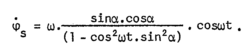
plane 4 still assumes a position deviating from this orientation. Through the implementation of certain compensation methods however, it is possible to reduce the effect of the control errors drastically; notably the effect of the w-component of Ms and can be counteracted by applying feedforward control, dependent upon the a and B values, in the servomechanisms. With this control the plane is forced to stabilise in a position deviating from the desired orientation in such a way that, through the occurrence of the above disturbances, still a stabilisation in the desired plane is realised. This compensation requires no additional motor torque, provided a direct driving motor is used. Compensation of the control errors caused by the 3w-component of M however requires an additional motor torque, as well as rather extensive calculations. Because the control errors caused by the 3w-component are in practice of limited magnitude, they normally need not be compensated. - The block diagram of Fig. 2 illustrates the servomechanism for one of the stabilisation axes together with a feasible embodiment of the control error compensation means. The servomechanism is constituted by a position feedback combination of at least a servo amplifier and motor. This combination with a direct coupled load is designated by the numeral 5. The combination of servo amplifier and motor is depicted functionally only to be able to determine the transfer function. Apart from the control voltage Ei, the sum of the disturbing torques acts on the combination; of these torques, only the non-uniformity torque Ms is taken into consideration. Further the stator rotation disturbance component ϕs, producing an electric counter-voltage, acts on the motor drive. In the embodiment in question the servo amplifier comprises a current feedback circuit. The relationship between inputs Ei, M and


- In a position feedback circuit, whose input signal is represented by ϕ' i and where the angular difference between rotor and stator is fed back to the input, the relationship between ϕ' i, Ms and


- To keep the required motor torque low, but without the control errors reaching extremely high values, and to prevent mechanical resonances in the desired lightweight and hence relatively weak construction, a relatively narrow servo bandwidth near the frequency range of the Ms and


- With the rotation axis in the vertical position, ϕ' i + ϕs = 0, M s = 0 and

Plane 4 is stabilised at the desired (horizontal) position about the axis considered. With the rotation axis in an inclined position, the control error within the frequency range in question equals:
plane 4 be stabilised at the desired value about the axis considered, the input signal ϕ' i of the servomechanism consists of a signal ϕi, representing the desired value at which the angular difference between rotor and stator of the axis concerned is controlled, and a compensation signal ϕc for the control errors incurred. This compensation signal is dependent upon the inclined position a of the platform and position B of the rotation axis measured in the plane of the platform: ϕc=F(α,B)≃Δϕr. A computer 7 supplies the input signal ϕ' i of the servomechanism. This computer comprises a converter 8 and a feedforward circuit 9. In converter 8 the ϕi signal is obtained from the platform inclined position a, measured with respect to an earth-fixed reference system, and position B of the rotation axis. The feedforward circuit 9 comprises a velocity feedforward depending upon the angular velocity cv,

- Fig. 2 further illustrates a digital-to-
analogue converter 10 and an analogue-to-digital converter 11 to realise the connection between the computer and the particular servomechanism. It should also be noted that in the embodiment in question the servomechanism is of the electro-mechanical design; it is however also possible to utilise a hydraulic or pneumatic servo.
Claims (7)


Applications Claiming Priority (2)
| Application Number | Priority Date | Filing Date | Title |
|---|---|---|---|
| NL8204027 | 1982-10-19 | ||
| NL8204027A NL8204027A (en) | 1982-10-19 | 1982-10-19 | DEVICE FOR STABILIZING A ROAD SEARCH INSTALLED ON A VEHICLE OR VESSEL. |
Publications (2)
| Publication Number | Publication Date |
|---|---|
| EP0107232A1 true EP0107232A1 (en) | 1984-05-02 |
| EP0107232B1 EP0107232B1 (en) | 1988-05-11 |
Family
ID=19840433
Family Applications (1)
| Application Number | Title | Priority Date | Filing Date |
|---|---|---|---|
| EP83201430A Expired EP0107232B1 (en) | 1982-10-19 | 1983-10-06 | Stabilisation aid for a vehicle- or vessel-borne search unit |
Country Status (7)
| Country | Link |
|---|---|
| US (1) | US4680521A (en) |
| EP (1) | EP0107232B1 (en) |
| JP (1) | JPS5994104A (en) |
| AU (1) | AU569044B2 (en) |
| CA (1) | CA1208339A (en) |
| DE (1) | DE3376601D1 (en) |
| NL (1) | NL8204027A (en) |
Cited By (6)
| Publication number | Priority date | Publication date | Assignee | Title |
|---|---|---|---|---|
| EP0433971A1 (en) * | 1989-12-22 | 1991-06-26 | Alcatel Telspace | Device for measuring the movements of flexion of an antenna support mast and application for the pointing control of a motorised antenna |
| EP0338379A3 (en) * | 1988-04-12 | 1992-06-17 | Nippon Steel Corporation | Antenna apparatus and attitude control method |
| EP0607070A1 (en) * | 1993-01-15 | 1994-07-20 | Thomson-Csf | Device for stabilisation of the beam direction of an electronic scanning antenna rigidly fixed on a vehicle |
| US6969025B1 (en) | 1988-10-24 | 2005-11-29 | Mbda Uk Limited | Servo actuation systems |
| WO2010040237A1 (en) * | 2008-10-10 | 2010-04-15 | Thales Suisse Sa | Stabilization of a mast for vehicles and ships |
| RU2477834C1 (en) * | 2011-11-25 | 2013-03-20 | Открытое акционерное общество "Концерн "Центральный научно-исследовательский институт "Электроприбор" | Method for platform gyroscopic stabilisation |
Families Citing this family (6)
| Publication number | Priority date | Publication date | Assignee | Title |
|---|---|---|---|---|
| US4920350A (en) * | 1984-02-17 | 1990-04-24 | Comsat Telesystems, Inc. | Satellite tracking antenna system |
| US4949026A (en) * | 1987-12-07 | 1990-08-14 | Mead John A | Robot arm space stabilizer |
| US4912753A (en) * | 1988-04-04 | 1990-03-27 | Hughes Aircraft Company | Robot axis controller employing feedback and open loop (feedforward) control |
| US5124938A (en) * | 1990-07-23 | 1992-06-23 | Recon/Optical, Inc. | Gyroless platform stabilization techniques |
| NL1006599C2 (en) * | 1997-07-16 | 1999-01-19 | Hollandse Signaalapparaten Bv | System for stabilizing an object placed on a movable platform. |
| JP4087355B2 (en) * | 2004-05-14 | 2008-05-21 | 三菱電機株式会社 | Tracking equipment |
Citations (2)
| Publication number | Priority date | Publication date | Assignee | Title |
|---|---|---|---|---|
| US3358285A (en) * | 1965-02-01 | 1967-12-12 | Hollandse Signaalapparaten Bv | Shipborne radar systems |
| US4143312A (en) * | 1976-11-15 | 1979-03-06 | The Marconi Company Limited | Stabilized platforms |
Family Cites Families (12)
| Publication number | Priority date | Publication date | Assignee | Title |
|---|---|---|---|---|
| US3741474A (en) * | 1970-02-24 | 1973-06-26 | Tokyo Keiki Kk | Autopilot system |
| US3832609A (en) * | 1973-02-05 | 1974-08-27 | Woodward Governor Co | Slip detection system |
| SE371615C (en) * | 1973-04-06 | 1975-04-28 | Asea Ab | |
| JPS516637A (en) * | 1974-07-05 | 1976-01-20 | Anritsu Electric Co Ltd | SHIKOSEIKUCHUSENTORITSUKESO |
| SE400236B (en) * | 1976-07-15 | 1978-03-20 | Asea Ab | DEVICE FOR A MOTOR POWERED VEHICLE |
| JPS5376749U (en) * | 1976-11-30 | 1978-06-27 | ||
| US4156241A (en) * | 1977-04-01 | 1979-05-22 | Scientific-Atlanta, Inc. | Satellite tracking antenna apparatus |
| JPS60277B2 (en) * | 1977-12-28 | 1985-01-07 | 株式会社トキメック | Marine automatic steering system |
| JPS58722B2 (en) * | 1978-06-23 | 1983-01-07 | 株式会社小松製作所 | Reduction sintering method for high speed steel powder |
| US4382216A (en) * | 1979-01-18 | 1983-05-03 | Fmc Corporation | System for controlling the movement of a rotatable member |
| US4278927A (en) * | 1979-03-05 | 1981-07-14 | Northrop Corporation | Axial gap permanent magnet motor |
| US4418306A (en) * | 1981-11-06 | 1983-11-29 | The United States Of America As Represented By The Secretary Of The Navy | Directional data stabilization system |
-
1982
- 1982-10-19 NL NL8204027A patent/NL8204027A/en not_active Application Discontinuation
-
1983
- 1983-10-06 EP EP83201430A patent/EP0107232B1/en not_active Expired
- 1983-10-06 DE DE8383201430T patent/DE3376601D1/en not_active Expired
- 1983-10-12 AU AU20092/83A patent/AU569044B2/en not_active Ceased
- 1983-10-17 CA CA000439128A patent/CA1208339A/en not_active Expired
- 1983-10-19 JP JP58194463A patent/JPS5994104A/en active Granted
-
1986
- 1986-03-21 US US06/842,765 patent/US4680521A/en not_active Expired - Fee Related
Patent Citations (2)
| Publication number | Priority date | Publication date | Assignee | Title |
|---|---|---|---|---|
| US3358285A (en) * | 1965-02-01 | 1967-12-12 | Hollandse Signaalapparaten Bv | Shipborne radar systems |
| US4143312A (en) * | 1976-11-15 | 1979-03-06 | The Marconi Company Limited | Stabilized platforms |
Non-Patent Citations (1)
| Title |
|---|
| ADVANCES IN INSTRUMENTATION, vol. 24, part 3, Proceedings of the 24th Annual ISA Conference, Houston, 27th-30th October 1969, pages 69-631.1 - 69-631.10, Pittsburgh, USA * |
Cited By (12)
| Publication number | Priority date | Publication date | Assignee | Title |
|---|---|---|---|---|
| EP0338379A3 (en) * | 1988-04-12 | 1992-06-17 | Nippon Steel Corporation | Antenna apparatus and attitude control method |
| EP0608000A1 (en) * | 1988-04-12 | 1994-07-27 | Nippon Steel Corporation | Antenna apparatus and attitude control method |
| US6969025B1 (en) | 1988-10-24 | 2005-11-29 | Mbda Uk Limited | Servo actuation systems |
| EP0433971A1 (en) * | 1989-12-22 | 1991-06-26 | Alcatel Telspace | Device for measuring the movements of flexion of an antenna support mast and application for the pointing control of a motorised antenna |
| FR2656416A1 (en) * | 1989-12-22 | 1991-06-28 | Alcatel Transmission | DEVICE FOR MEASURING THE FLEXION MOVEMENTS OF AN ANTENNA SUPPORT MATERIAL AND APPLICATION TO THE CONTROL OF THE POINTING OF A MOTORIZED ANTENNA. |
| US5151710A (en) * | 1989-12-22 | 1992-09-29 | Alcatel Transmission Par Faisceaux Hertziens | Apparatus for measuring bending movements of an antenna support mast, and application thereof to controlling the pointing of a motor-driven antenna |
| EP0607070A1 (en) * | 1993-01-15 | 1994-07-20 | Thomson-Csf | Device for stabilisation of the beam direction of an electronic scanning antenna rigidly fixed on a vehicle |
| FR2700640A1 (en) * | 1993-01-15 | 1994-07-22 | Thomson Csf | Device for stabilizing the beam pointing of an electronic scanning antenna rigidly fixed on a mobile. |
| US5440314A (en) * | 1993-01-15 | 1995-08-08 | Thomson-Csf | Device to stabilize the beam of an electronic scanning antenna rigidly fixed to a moving body |
| WO2010040237A1 (en) * | 2008-10-10 | 2010-04-15 | Thales Suisse Sa | Stabilization of a mast for vehicles and ships |
| US8494725B2 (en) | 2008-10-10 | 2013-07-23 | Thales Suisse Sa | Stabilization of a mast for vehicles and ships |
| RU2477834C1 (en) * | 2011-11-25 | 2013-03-20 | Открытое акционерное общество "Концерн "Центральный научно-исследовательский институт "Электроприбор" | Method for platform gyroscopic stabilisation |
Also Published As
| Publication number | Publication date |
|---|---|
| US4680521A (en) | 1987-07-14 |
| JPH0519724B2 (en) | 1993-03-17 |
| AU569044B2 (en) | 1988-01-21 |
| CA1208339A (en) | 1986-07-22 |
| AU2009283A (en) | 1984-05-03 |
| EP0107232B1 (en) | 1988-05-11 |
| JPS5994104A (en) | 1984-05-30 |
| NL8204027A (en) | 1984-05-16 |
| DE3376601D1 (en) | 1988-06-16 |
Similar Documents
| Publication | Publication Date | Title |
|---|---|---|
| EP0107232B1 (en) | Stabilisation aid for a vehicle- or vessel-borne search unit | |
| US4393597A (en) | Stabilized sighting devices for vehicles | |
| US5517204A (en) | Antenna directing apparatus | |
| US4070674A (en) | Doppler heading attitude reference system | |
| JPH08244695A (en) | Energy storage and recovery system and method | |
| JP2014133600A (en) | Hoisted load attitude control apparatus | |
| US5875676A (en) | Non colocated rate sensing for control moment gyroscopes | |
| US5608634A (en) | Low noise spacecraft body rate sensing arrangement for attitude control | |
| EP0520165B1 (en) | Momentum wheel platform steering system and method | |
| JP2001502271A (en) | Feedback motion compensation of spacecraft payload | |
| US20030034928A1 (en) | Positioning control apparatus and the method | |
| US5416976A (en) | Gyro compass | |
| US4638221A (en) | Reaction force compensator | |
| US3936716A (en) | Stabilisation system | |
| US3456511A (en) | Stabilization control system | |
| EP0116912B1 (en) | Method of controlling motor speed | |
| US3432856A (en) | Doppler inertial navigation system | |
| EP0321513B1 (en) | Nutation sensor and nutation control system for a dual-spin stabilized satellite | |
| US9617015B2 (en) | Method of commanding an attitude control system and attitude control system of a space vehicle | |
| US4645994A (en) | Space-referenced, rate-stabilized multiple-gimbal-platform system | |
| US3664200A (en) | Stable base mounts | |
| JP2596376B2 (en) | Antenna drive control device | |
| US2756598A (en) | Gyro roll compensating system | |
| JP2658937B2 (en) | Satellite 3-axis attitude control system | |
| JP2609967B2 (en) | Driving device for remote controlled object |
Legal Events
| Date | Code | Title | Description |
|---|---|---|---|
| PUAI | Public reference made under article 153(3) epc to a published international application that has entered the european phase |
Free format text: ORIGINAL CODE: 0009012 |
|
| AK | Designated contracting states |
Designated state(s): BE CH DE FR GB IT LI NL SE |
|
| 17P | Request for examination filed |
Effective date: 19841015 |
|
| 17Q | First examination report despatched |
Effective date: 19860616 |
|
| GRAA | (expected) grant |
Free format text: ORIGINAL CODE: 0009210 |
|
| AK | Designated contracting states |
Kind code of ref document: B1 Designated state(s): BE CH DE FR GB IT LI NL SE |
|
| REF | Corresponds to: |
Ref document number: 3376601 Country of ref document: DE Date of ref document: 19880616 |
|
| ITF | It: translation for a ep patent filed | ||
| ET | Fr: translation filed | ||
| PLBI | Opposition filed |
Free format text: ORIGINAL CODE: 0009260 |
|
| 26 | Opposition filed |
Opponent name: CONTRAVES AG Effective date: 19890209 |
|
| NLR1 | Nl: opposition has been filed with the epo |
Opponent name: CONTRAVES AG |
|
| ITTA | It: last paid annual fee | ||
| PGFP | Annual fee paid to national office [announced via postgrant information from national office to epo] |
Ref country code: SE Payment date: 19910917 Year of fee payment: 9 Ref country code: DE Payment date: 19910917 Year of fee payment: 9 |
|
| PGFP | Annual fee paid to national office [announced via postgrant information from national office to epo] |
Ref country code: FR Payment date: 19910918 Year of fee payment: 9 |
|
| PGFP | Annual fee paid to national office [announced via postgrant information from national office to epo] |
Ref country code: GB Payment date: 19910924 Year of fee payment: 9 |
|
| PGFP | Annual fee paid to national office [announced via postgrant information from national office to epo] |
Ref country code: CH Payment date: 19910927 Year of fee payment: 9 |
|
| PGFP | Annual fee paid to national office [announced via postgrant information from national office to epo] |
Ref country code: BE Payment date: 19911016 Year of fee payment: 9 |
|
| PGFP | Annual fee paid to national office [announced via postgrant information from national office to epo] |
Ref country code: NL Payment date: 19911031 Year of fee payment: 9 |
|
| NLT1 | Nl: modifications of names registered in virtue of documents presented to the patent office pursuant to art. 16 a, paragraph 1 |
Owner name: HASRODE B.V. TE EINDHOVEN. |
|
| NLS | Nl: assignments of ep-patents |
Owner name: HOLLANDSE SIGNAALAPPARATEN B.V. TE HENGELO (O.). |
|
| REG | Reference to a national code |
Ref country code: GB Ref legal event code: 732 |
|
| RDAG | Patent revoked |
Free format text: ORIGINAL CODE: 0009271 |
|
| STAA | Information on the status of an ep patent application or granted ep patent |
Free format text: STATUS: PATENT REVOKED |
|
| REG | Reference to a national code |
Ref country code: FR Ref legal event code: TP Ref country code: FR Ref legal event code: CD Ref country code: FR Ref legal event code: CA |
|
| 27W | Patent revoked |
Effective date: 19920418 |
|
| GBPR | Gb: patent revoked under art. 102 of the ep convention designating the uk as contracting state | ||
| REG | Reference to a national code |
Ref country code: CH Ref legal event code: PL |
|
| NLR2 | Nl: decision of opposition | ||
| BECA | Be: change of holder's address |
Free format text: 920923 *HOLLANDSE SIGNAALAPPARATEN B.V.:ZUIDELIJKE HAVENWEG 40, 7554 RR HENGELO |
|
| BECH | Be: change of holder |
Free format text: 920923 *HOLLANDSE SIGNAALAPPARATEN B.V. |
|
| BERE | Be: lapsed |
Owner name: HOLLANDSE SIGNAALAPPARATEN B.V. Effective date: 19921031 |
|
| EUG | Se: european patent has lapsed |
Ref document number: 83201430.2 Effective date: 19921007 |
|
| APAH | Appeal reference modified |
Free format text: ORIGINAL CODE: EPIDOSCREFNO |
|
| PLAB | Opposition data, opponent's data or that of the opponent's representative modified |
Free format text: ORIGINAL CODE: 0009299OPPO |