EP0108051B1 - Regulator für eine motorgetriebene pumpe - Google Patents
Regulator für eine motorgetriebene pumpe Download PDFInfo
- Publication number
- EP0108051B1 EP0108051B1 EP82901564A EP82901564A EP0108051B1 EP 0108051 B1 EP0108051 B1 EP 0108051B1 EP 82901564 A EP82901564 A EP 82901564A EP 82901564 A EP82901564 A EP 82901564A EP 0108051 B1 EP0108051 B1 EP 0108051B1
- Authority
- EP
- European Patent Office
- Prior art keywords
- diaphragm
- chamber
- pump
- arrangement
- regulator
- Prior art date
- Legal status (The legal status is an assumption and is not a legal conclusion. Google has not performed a legal analysis and makes no representation as to the accuracy of the status listed.)
- Expired
Links
- 230000033228 biological regulation Effects 0.000 claims abstract description 6
- 230000005540 biological transmission Effects 0.000 claims abstract description 5
- 239000012530 fluid Substances 0.000 claims abstract description 4
- 235000001674 Agaricus brunnescens Nutrition 0.000 claims description 13
- 239000007788 liquid Substances 0.000 abstract description 16
- 230000003247 decreasing effect Effects 0.000 abstract 1
- 238000006073 displacement reaction Methods 0.000 abstract 1
- 230000001105 regulatory effect Effects 0.000 description 3
- 230000000694 effects Effects 0.000 description 2
- 238000005086 pumping Methods 0.000 description 2
- 230000007423 decrease Effects 0.000 description 1
- 230000001419 dependent effect Effects 0.000 description 1
- 230000000149 penetrating effect Effects 0.000 description 1
- 125000006850 spacer group Chemical group 0.000 description 1
Images


Classifications
-
- F—MECHANICAL ENGINEERING; LIGHTING; HEATING; WEAPONS; BLASTING
- F04—POSITIVE - DISPLACEMENT MACHINES FOR LIQUIDS; PUMPS FOR LIQUIDS OR ELASTIC FLUIDS
- F04B—POSITIVE-DISPLACEMENT MACHINES FOR LIQUIDS; PUMPS
- F04B49/00—Control, e.g. of pump delivery, or pump pressure of, or safety measures for, machines, pumps, or pumping installations, not otherwise provided for, or of interest apart from, groups F04B1/00 - F04B47/00
- F04B49/20—Control, e.g. of pump delivery, or pump pressure of, or safety measures for, machines, pumps, or pumping installations, not otherwise provided for, or of interest apart from, groups F04B1/00 - F04B47/00 by changing the driving speed
Definitions
- the invention relates to a regulator for a motor driven pump for the regulation of the output pressure in accordance with a predetermined value according to the precharacterizing portion of claim 1.
- the US-A-2 989 000 shows a regulator for a motor driven pump, in which the pressure difference between the suction and the pressure side of the pump is regulated.
- the actual regulating element, the piston is applied with the pumping pressure on the suction side from below and the pumping pressure on the pressure side from above, both application surfaces being of the same size.
- the piston moves downwards resp. upwards within the cylinder and, during such a lifting movement, operates a lever which controls the output efficiency of the energy source via a connecting element.
- the drive power supplied to the pump and thus the conditions of the pump on the pressure side are always directly dependent upon the suction pressure of the pump in the case of this regulator.
- the problem underlying the invention is to develop a regulator for a motor driven pump in which the conditions of the pump on the pressure side are largely independent of the conditions on the suction side in the admissible range of operation.
- the actual regulation of the output efficiency of the energy source for the pump is, at first, exclusively controlled by the pressure of the pump on the pressure side and the pressure of the atmosphere. Only if the admissible range of operation is left, the pressure of the pump on the suction side becomes an additional control factor.
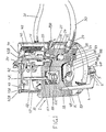
- the regulator which in the first place is intended to find an application in pumps working with a liquid, has a regulator housing 1, which is formed by a number of housing parts 1A, 1B, 1C and 1D respectively, which are coupled together and exhibit a number of recesses 2A, 2B etc., which in not connected condition of the housing' parts 1A-1D are open and located right in front of each other in order to form a number of chambers 2 etc. and spaces, the function of which will be explained further on.
- the housing 1 supports a preferably angular arm 4, which is an element of a power transmission means 4, 10 and pivoted on a shaft 5, which is supported by a fastening means 6 on the housing 1. Said arm 4 by the bias of a spring 7 tends with one angular arm portion 4A to be moved in direction towards the housing 1, while at the same time it is abutting against one end 8A of a piston rod 8, which through an opening 9 protrudes out of the housing 1.
- the other angular arm portion 4B of the pivoting arm 4 is connected with the power control of the propulsion means of the pump, i.e. the motor, said connection by way of example comprising a wire 10 or other similar transmission means, which forms the other element of the power transmission means 4, 10.
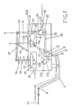
- the spring biassed piston rod 8 through the opening 9 penetrates into a space 11, which extends through the three housing parts 1B, 1C and 1D, and in the interspace between the same clamps two diaphragm elements 12A and 12B repsectively, which together form a double diaphragm 12.
- This double diaphragm 12 is by means of the end portion 8B of the piston rod 8, that penetrates into the housing 1, and a nut 13 and with an interspaced spacer block 14 connected with the piston rod 8, as is shown in Fig. 2 in the drawing.
- the diaphragm element 12A which is one of the two diaphragm elements 12A and 12B respectively of the double diaphragm 12 is held nearest to the end portion 8B of the piston rod 8, which is penetrating into the housing 1, and exhibits a considerably greater area than the other element 12B of the double diaphragm 12, the relation preferably being in the order of 4:1 as a condition for the satisfactory function of the regulator.
- Said middle chamber 18 is in its turn via and additional duct 19 in communication with a space 20, which is a part of a passage 20, 24, 25 and in which a mushroom valve 21 or similar can be displaced.
- the chamber 25 and the opening 24 are also parts of the passage 20, 24, 25.
- a boss 35A is provided on the piston 35 and acts as a stop means.
- the one part of the chamber 2, which is located on the upper side of the diaphragm 34, is in communication with the surrounding atmosphere via a passage 37.
- a pressure spring 38 abuts with one end 38A against the upper portion of a bar 36, on which a swinging arm 39 is pivoted with one end 39A.
- the other end 39B of the swinging arm 39 is via an articulation 40 pivoted on a regulating pin 41 connected with the mushroom valve 21 and protruding out of the housing 1.
- the swinging arm 39 has a shaft 42 extending across the swinging arm 39 and at each one of its respective two ends supporting an angled arm 43 and 44 respectively, which are rigidly connected with said shaft 42, each one of said angled arms (43, 44) being pivoted in upright projections 45 and 46 of the housing 1.
- a spring element in form of a helical spring 47 is with one end 47A connected with the shaft 42.
- the other end in form of a supporting means 47B of the helical spring 47 is in its turn connected with one side 48A of the angle of an angular part 48 pivoted on a shaft 49 in the housing 1.
- the other side 48B of the angular part 48 is pivoted on one end 50A of a shaft 50 provided with threads and screwed into a threaded hole 50B of the housing 1.
- a setting control in form of a wheel 51 is rigidly connected with said shaft 50, which is provided with threads, at the protruding end 50C of the same and forms a throttling means by means of which the supporting point of the spring element 47 can be changed and thereby adjust the spring element 47, so that it will have the desired spring force.
- the shaft 42 abuts with one portion 42C against the upper end 53A of a pin 52, which through an opening 53 penetrates into the housing 1 and enters the middle chamber 18.
- a diaphragm 54 which by means of a supporting part 52B and nuts 55 is supported on the shaft 52, is connected with said shaft 52, which exhibits a bottom portion forming a boss 52C, which acts as a stop means.
- the diaphragm 54 which is clamped between the housing parts 1A and 1B, divides the middle chamber 18 in a bottom chamber 18 and an upper chamber 56, which upper chamber 56 is in communication with the atmosphere via a duct 57.
- the output pressure from the pump is then somewhat reduced, which fall of pressure is transmitted to the chamber 27 between the two diaphragm elements 12A and 12B of the double diaphragm 12, this taking place via the hose 30, the chamber 25 and a duct 26.
- the equilibrium which has previously prevailed in said chamber 27 and which has previously been adjusted by means of the setting control built as a throttling means 51, is then interrupted.
- the double diaphragm 12 on the account of the difference in size of the areas of the diaphragm element 12A, 12B thereof thereby tends to be pressed in direction towards the maximum position.
- this is the direction, in which the piston rod 8 is projected in downwards direction, so that the arm 4 gradually actuates the wire 10 causing the same to increase the gas supply to the pump motor.
- the pressure in the first chamber 16 is reduced, the diaphragm 54, which is balanced against the spring element 47, sinking in downwards direction towards the boss 52C.
- the swinging arm 39 which constitutes the connection between the diaphragm 54 and the mushroom valve 21 then will actuate the mushroom valve 21, so that it will press down the ball valve body 22 by means of the downwards projecting end 21A.
- the gas supply to the motor is increased, which causes the pressure from the pump to increase.
- the setting of the spring element 47 warrants a certain pressure in the first chamber 16, which in its turn warrants a pressure, that is proportionally greater with respect to the areas of the diaphragm elements 12A and 12B of the double diaphragm 12, i.e. the output pressure, which is transported from the pump.
- the diaphragm 54 When a state of equilibrium has been obtained the diaphragm 54 is pressed to a middle position in which position the protruding end 21A of the mushroom valve 21 abuts exactly closely against the ball valve body 22. In this position an exceedingly small quantity of liquid flows through the regulator and out via the outlet passage 20A to the surrounding air. The fact that liquid flows past the mushroom valve 21 in this position is a necessary feature for the satisfactory function of the diaphragm 34 in the second chamber 2, as will be explained further on. The described sequence has brought about that the pump now pumps a greater quantity of liquid at the same pressure as before.
- the double diaphragm 12 has then occupied a position, which corresponds to the reduced output of liquid from the pump, i.e. an equilibrium has been obtained. Also the mushroom valve 21 has occupied a position of equilibrium, while the ball valve body 22 substantially completely blocks the passage 24. In the case described the pump now pumps a smaller quantity of liquid than before at the same pressure. It should be noted that the double diaphragm 12 occupies its maximum position and minimum position respectively, when the capacity of the pump just has been reached or exceeded and when little or no liquid at all flows out of the pump respectively.
- the diaphragm 34 is therefore adjusted to the effect that at an absolute pressure of approximately 0,3 Bar and less it will impede the opening of the passage 24, so that the pressure in the first chamber 16 is not increased and does not increase of the gas supply.
- the gas supply is instead now reduced as a consequence of the small quantity of liquid flowing past the mushroom valve 21. Thanks to the diaphragm 34 an equilibrium is now reached with an input pressure of the pump of approximately 0,3 kg completely independent of the output pressure of the pump. Thus the pump can pump the maximum quantity of liquid permitted by the prevailing conditions.
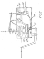
- the regulator schematically illustrated in Fig. 7 essentially corresponds to the regulator described and illustrated in the previous drawings with the exception that the double diaphragm has been substituted by a valve arrangement 12 2 comprising a number of elements, more particularly one diaphragm element 12A 2 and a piston element 12B 2 . Both these elements are connected with each other in a similar way as the double diaphragm 12 in the previously described regulator.
- a chamber 27 2 debouching in the atmosphere is formed between the diaphragm element 12A 2 and the piston element 12B 2 .
- a chamber 16 2 which borders upon the diaphragm element 12A 2 , corresponds to the above said first chamber 16.
- a further chamber 15 2 which borders upon the piston element 128 2 , and which is sealed from the atmosphere, is via a duct 26 2 connected with a secondary valve arrangement 21 2 , 22 2 similar to the one previously described.
- the active pressure surface of the diaphragm element 12A 2 and the piston element 12B 2 respectively differ from each other in the same manner as in the described double diaphragm 12, by way of a suggestion likewise with the relation 4:1.
- the function of the additionally described regulator is substantially identical to the function of the previously described regulator in spite of the fact that the space 27 2 and 15 2 respectively, which is defined by the elements 12A 2 and 12B 2 , and borders upon a valve element 12B 2 respectively, debouches in the atmosphere and is connected with the first chamber 16 respectively, i.e. quite contrary to what is the case in the described double diaphragm 12.
Landscapes
- Engineering & Computer Science (AREA)
- Mechanical Engineering (AREA)
- General Engineering & Computer Science (AREA)
- Reciprocating Pumps (AREA)
- Control Of Fluid Pressure (AREA)
- Control Of Positive-Displacement Pumps (AREA)
- Control Of Motors That Do Not Use Commutators (AREA)
- Control Of Eletrric Generators (AREA)
- Fluid-Pressure Circuits (AREA)
Claims (10)
Priority Applications (1)
| Application Number | Priority Date | Filing Date | Title |
|---|---|---|---|
| AT82901564T ATE29770T1 (de) | 1982-05-13 | 1982-05-13 | Regulator fuer eine motorgetriebene pumpe. |
Applications Claiming Priority (1)
| Application Number | Priority Date | Filing Date | Title |
|---|---|---|---|
| PCT/SE1982/000169 WO1983004074A1 (en) | 1982-05-13 | 1982-05-13 | Regulator |
Publications (2)
| Publication Number | Publication Date |
|---|---|
| EP0108051A1 EP0108051A1 (de) | 1984-05-16 |
| EP0108051B1 true EP0108051B1 (de) | 1987-09-16 |
Family
ID=20345708
Family Applications (1)
| Application Number | Title | Priority Date | Filing Date |
|---|---|---|---|
| EP82901564A Expired EP0108051B1 (de) | 1982-05-13 | 1982-05-13 | Regulator für eine motorgetriebene pumpe |
Country Status (5)
| Country | Link |
|---|---|
| US (1) | US4560322A (de) |
| EP (1) | EP0108051B1 (de) |
| AT (1) | ATE29770T1 (de) |
| DE (1) | DE3277322D1 (de) |
| WO (1) | WO1983004074A1 (de) |
Families Citing this family (1)
| Publication number | Priority date | Publication date | Assignee | Title |
|---|---|---|---|---|
| US5224836A (en) * | 1992-05-12 | 1993-07-06 | Ingersoll-Rand Company | Control system for prime driver of compressor and method |
Family Cites Families (5)
| Publication number | Priority date | Publication date | Assignee | Title |
|---|---|---|---|---|
| US2704631A (en) * | 1955-03-22 | bancel | ||
| US2816507A (en) * | 1955-05-17 | 1957-12-17 | Gore William M Le | Variable stroke fluid drive mechanism |
| US2989000A (en) * | 1959-12-01 | 1961-06-20 | Santa Fe Mfg Corp | Pressure governor |
| US3796515A (en) * | 1972-06-01 | 1974-03-12 | Atlas Copco Ab | Plants comprising a combustion engine and a compressor driven by said engine |
| US4140436A (en) * | 1977-08-19 | 1979-02-20 | Virginia Chemicals Inc. | Pressure control device for fluid systems |
-
1982
- 1982-05-13 EP EP82901564A patent/EP0108051B1/de not_active Expired
- 1982-05-13 WO PCT/SE1982/000169 patent/WO1983004074A1/en not_active Ceased
- 1982-05-13 US US06/573,936 patent/US4560322A/en not_active Expired - Fee Related
- 1982-05-13 DE DE8282901564T patent/DE3277322D1/de not_active Expired
- 1982-05-13 AT AT82901564T patent/ATE29770T1/de not_active IP Right Cessation
Also Published As
| Publication number | Publication date |
|---|---|
| ATE29770T1 (de) | 1987-10-15 |
| EP0108051A1 (de) | 1984-05-16 |
| US4560322A (en) | 1985-12-24 |
| WO1983004074A1 (en) | 1983-11-24 |
| DE3277322D1 (en) | 1987-10-22 |
Similar Documents
| Publication | Publication Date | Title |
|---|---|---|
| US4080110A (en) | Control system for variable capacity gas compressor | |
| JPS589276B2 (ja) | パイロット作動負荷補償可変容量ポンプ | |
| JPH0255642B2 (de) | ||
| JPH0526955B2 (de) | ||
| US5320499A (en) | Open-loop hydraulic supply system | |
| JPH07107402B2 (ja) | 少なくとも1基のポンプから液圧が供給されている少なくとも2台の液圧消費装置の制御装置 | |
| US4966183A (en) | Pressure regulator | |
| US6109030A (en) | Apparatus and method for ganging multiple open circuit pumps | |
| JP2646224B2 (ja) | 少なくとも2つのアクチュエータの流体圧駆動用制御装置 | |
| US4665939A (en) | Priority control for hydraulic consumers | |
| JPH073270B2 (ja) | 真空調整器 | |
| EP0108051B1 (de) | Regulator für eine motorgetriebene pumpe | |
| US3736753A (en) | Hydraulic drive | |
| GB2277895A (en) | Fastening tool having improved regulator device | |
| GB1267461A (en) | Hydraulic control apparatus for driving a drivable member | |
| JPH0792087B2 (ja) | 印加圧力を有する駆動系のための制御装置 | |
| US3987624A (en) | Hydraulic drive control system | |
| JP2747637B2 (ja) | 可変ストローク式軸線方向往復動型ポンプのための出力制限制御装置 | |
| EP0112791B1 (de) | Automatische Druckeinstellung für druckausgeglichene Pumpen | |
| US3941508A (en) | Automatic pressure control system | |
| EP0226125B1 (de) | Pumpanordnung mit veränderlicher Verdrängung | |
| US4284389A (en) | Input torque control system for a variable displacement pump | |
| US4509902A (en) | Power regulating device for a hydrostatic pump | |
| JPH0341123Y2 (de) | ||
| US4762141A (en) | Fluid flow regulator |
Legal Events
| Date | Code | Title | Description |
|---|---|---|---|
| PUAI | Public reference made under article 153(3) epc to a published international application that has entered the european phase |
Free format text: ORIGINAL CODE: 0009012 |
|
| 17P | Request for examination filed |
Effective date: 19840112 |
|
| AK | Designated contracting states |
Kind code of ref document: A1 Designated state(s): AT BE CH DE FR GB LI LU NL |
|
| GRAA | (expected) grant |
Free format text: ORIGINAL CODE: 0009210 |
|
| AK | Designated contracting states |
Kind code of ref document: B1 Designated state(s): AT BE CH DE FR GB LI LU NL |
|
| REF | Corresponds to: |
Ref document number: 29770 Country of ref document: AT Date of ref document: 19871015 Kind code of ref document: T |
|
| REF | Corresponds to: |
Ref document number: 3277322 Country of ref document: DE Date of ref document: 19871022 |
|
| ET | Fr: translation filed | ||
| PLBE | No opposition filed within time limit |
Free format text: ORIGINAL CODE: 0009261 |
|
| STAA | Information on the status of an ep patent application or granted ep patent |
Free format text: STATUS: NO OPPOSITION FILED WITHIN TIME LIMIT |
|
| 26N | No opposition filed | ||
| PGFP | Annual fee paid to national office [announced via postgrant information from national office to epo] |
Ref country code: CH Payment date: 19920427 Year of fee payment: 11 |
|
| PGFP | Annual fee paid to national office [announced via postgrant information from national office to epo] |
Ref country code: GB Payment date: 19920429 Year of fee payment: 11 |
|
| PGFP | Annual fee paid to national office [announced via postgrant information from national office to epo] |
Ref country code: LU Payment date: 19920430 Year of fee payment: 11 |
|
| PGFP | Annual fee paid to national office [announced via postgrant information from national office to epo] |
Ref country code: BE Payment date: 19920513 Year of fee payment: 11 |
|
| PGFP | Annual fee paid to national office [announced via postgrant information from national office to epo] |
Ref country code: AT Payment date: 19920515 Year of fee payment: 11 |
|
| PGFP | Annual fee paid to national office [announced via postgrant information from national office to epo] |
Ref country code: FR Payment date: 19920525 Year of fee payment: 11 |
|
| PGFP | Annual fee paid to national office [announced via postgrant information from national office to epo] |
Ref country code: NL Payment date: 19920531 Year of fee payment: 11 |
|
| PGFP | Annual fee paid to national office [announced via postgrant information from national office to epo] |
Ref country code: DE Payment date: 19920630 Year of fee payment: 11 |
|
| EPTA | Lu: last paid annual fee | ||
| PG25 | Lapsed in a contracting state [announced via postgrant information from national office to epo] |
Ref country code: LU Free format text: LAPSE BECAUSE OF NON-PAYMENT OF DUE FEES Effective date: 19930513 Ref country code: GB Effective date: 19930513 Ref country code: AT Effective date: 19930513 |
|
| PG25 | Lapsed in a contracting state [announced via postgrant information from national office to epo] |
Ref country code: LI Effective date: 19930531 Ref country code: CH Effective date: 19930531 Ref country code: BE Effective date: 19930531 |
|
| BERE | Be: lapsed |
Owner name: ANDERSSON ULF Effective date: 19930531 |
|
| PG25 | Lapsed in a contracting state [announced via postgrant information from national office to epo] |
Ref country code: NL Effective date: 19931201 |
|
| GBPC | Gb: european patent ceased through non-payment of renewal fee |
Effective date: 19930513 |
|
| NLV4 | Nl: lapsed or anulled due to non-payment of the annual fee | ||
| PG25 | Lapsed in a contracting state [announced via postgrant information from national office to epo] |
Ref country code: FR Effective date: 19940131 |
|
| REG | Reference to a national code |
Ref country code: CH Ref legal event code: PL |
|
| PG25 | Lapsed in a contracting state [announced via postgrant information from national office to epo] |
Ref country code: DE Effective date: 19940201 |
|
| REG | Reference to a national code |
Ref country code: FR Ref legal event code: ST |