EP0108683B1 - Bedrucken von Gegenständen mittels Tintenstrahl - Google Patents
Bedrucken von Gegenständen mittels Tintenstrahl Download PDFInfo
- Publication number
- EP0108683B1 EP0108683B1 EP83402103A EP83402103A EP0108683B1 EP 0108683 B1 EP0108683 B1 EP 0108683B1 EP 83402103 A EP83402103 A EP 83402103A EP 83402103 A EP83402103 A EP 83402103A EP 0108683 B1 EP0108683 B1 EP 0108683B1
- Authority
- EP
- European Patent Office
- Prior art keywords
- marking
- marked
- products
- head
- axis
- Prior art date
- Legal status (The legal status is an assumption and is not a legal conclusion. Google has not performed a legal analysis and makes no representation as to the accuracy of the status listed.)
- Expired
Links
- 238000007641 inkjet printing Methods 0.000 title 1
- 238000000034 method Methods 0.000 claims abstract description 10
- 238000013459 approach Methods 0.000 claims description 4
- 239000000523 sample Substances 0.000 description 5
- 238000006073 displacement reaction Methods 0.000 description 3
- 238000011144 upstream manufacturing Methods 0.000 description 3
- 238000012423 maintenance Methods 0.000 description 1
- 239000002184 metal Substances 0.000 description 1
- 238000005096 rolling process Methods 0.000 description 1
- 238000005507 spraying Methods 0.000 description 1
Images

Classifications
-
- B—PERFORMING OPERATIONS; TRANSPORTING
- B41—PRINTING; LINING MACHINES; TYPEWRITERS; STAMPS
- B41J—TYPEWRITERS; SELECTIVE PRINTING MECHANISMS, i.e. MECHANISMS PRINTING OTHERWISE THAN FROM A FORME; CORRECTION OF TYPOGRAPHICAL ERRORS
- B41J2/00—Typewriters or selective printing mechanisms characterised by the printing or marking process for which they are designed
- B41J2/005—Typewriters or selective printing mechanisms characterised by the printing or marking process for which they are designed characterised by bringing liquid or particles selectively into contact with a printing material
- B41J2/01—Ink jet
-
- B—PERFORMING OPERATIONS; TRANSPORTING
- B41—PRINTING; LINING MACHINES; TYPEWRITERS; STAMPS
- B41J—TYPEWRITERS; SELECTIVE PRINTING MECHANISMS, i.e. MECHANISMS PRINTING OTHERWISE THAN FROM A FORME; CORRECTION OF TYPOGRAPHICAL ERRORS
- B41J3/00—Typewriters or selective printing or marking mechanisms characterised by the purpose for which they are constructed
- B41J3/407—Typewriters or selective printing or marking mechanisms characterised by the purpose for which they are constructed for marking on special material
- B41J3/4073—Printing on three-dimensional objects not being in sheet or web form, e.g. spherical or cubic objects
Definitions
- the present invention relates to the marking of products on parade, by ink jets. More particularly, the invention relates to a method and a device for marking in the parade by ink jets of a surface not parallel to the plane of travel of the products, in particular of a cylindrical surface such as the rolls of paper reels.
- Ink jet marking consists of spraying ink in given sequences from several aligned nozzles to form ink dots which define printing characters.
- Marking of paper reels with ink jets is known. It is carried out on the edge of the reels, in a straight line, by scrolling the reel in front of the marking device, or by moving it in front of it, the running plane being always parallel to the surface to be marked.
- the marking can also be carried out on the cylindrical or rolled part of the reel. It is then always carried out at a station where the coil, stationary in translation, can be driven in a rotational movement on itself (FR-A-2 398 611). It then requires significant means to rotate the coil on itself, and also a period of immobilization in translation of the coil at least equal to the duration of the marking.
- the invention provides a method and a device for marking products in parade by ink jets on at least one surface of said products, surface arranged not parallel to the plane of travel thereof, particularly simple method and device, easy to to implement and which do not require any immobilization of the products to be marked.
- the invention applies to the marking of many products of different shapes, having surfaces to be marked flat or curvilinear, for example products of triangular, curvilinear, cylindrical shape, etc.
- the product to be marked is moved in a rectilinear manner, opposite at least one marking head, the surface or surfaces to be marked being arranged not parallel to the plane of travel of the product, and the product (s) is marked running surfaces, elastically holding the marking head (s) perpendicular to the surface (s) to be marked, at a constant distance therefrom, throughout the marking operation.
- the reel can be placed on the straight conveyor, lying on the roll, its axis being perpendicular to the plane of the conveyor.
- the marking head is arranged above the conveyor and the marking at the parade is carried out from above the roll.
- the reel is placed upright on the edge, the marking head or heads then being placed on the side of the conveyor and the marking in the process is carried out from the side. It is thus advantageously possible to successively or simultaneously mark two opposite sides of the roll (or two lateral faces of a product of triangular shape for example).
- the inscription is substantially symmetrical with respect to this axial tilting plane.
- the invention also relates to a device for marking products in a parade, marking by ink jets on at least one surface of said products, arranged not parallel to the plane of travel thereof.
- the device according to the invention comprises a rectilinear conveyor for the products to be marked, at least one marking head disposed above the conveyor or on the side, this head being articulated around an axis parallel to the plane of travel of the products , at the end of a system with elastic movement and return, acting essentially perpendicular to the axis of the conveyor such as a spring or a jack, which ensures the maintenance of the head in the marking position during the whole operation, a guidance system determining the correct orientation of the marking head at all times.
- the guide system is a sensor which surrounds the marking head and which comprises rods terminated by rolling balls serving as touch points on the surface to be marked, in particular the roll of the spool to follow that -this without rubbing and possibly damaging the coil.
- two marking heads when the reel is placed on the edge, two marking heads can be associated, each of them operating simultaneously or separately on opposite sides of the roll relative to the axial plane of the reel, parallel to the movement of this one.
- the device comprises a system giving the marking head an upstream orientation, that is to say towards the center of the reel, when approaching the latter. It is for example a pneumatic system with adjustable stroke.
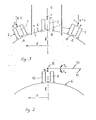
- a reel of paper standing on its edge is driven by a straight conveyor not shown in a forward movement according to arrow F.
- the marking head 2 is shown in three successive marking positions.
- Position A corresponds to the start of the marking.
- the marking head articulated around an axis 3 parallel to that of the coil, that is to say parallel to the plane of travel of the latter (the plane of travel passing through the axis of the coil), is oriented towards the center thereof, upstream, by a ball feeler 4 which follows the curvature of the coil, and which is integral with the head.
- the axis 3 is mounted at the end of a system with elastic travel and return 5 acting perpendicular to the axis of the conveyor. This system keeps the probe applied against the roll 6 of the coil and therefore the head close to the latter, thanks to the radial component R of the force which it exerts on the axis 3.
- the nozzles 7 by which the ink for printing is projected are arranged at a suitable and constant distance from the spool.
- the reel moves the probe and the marking head away from the axis of the conveyor and the system with elastic travel and return retracts perpendicularly according to the arrow F l .
- Position B generally corresponds to the middle position for marking. In this position, the head is located in the tilting plane b. The elastic system is retracted to the maximum.
- Position C corresponds to the end of the marking.
- the head is still oriented towards the center of the coil by the probe, but downstream this time.
- the elastic system is in its exit stroke along F z .
- FIG. 2 represents a variant implementation of the invention, but which applies the same principle of marking.
- the axis 8 around which the marking head 9 is articulated is mounted at the end of an oscillating arm 10, according to the arrows F 3 and F 4 around an axis 11 parallel to that of the coil.
- the oscillating arm 10 is disposed substantially along a parallel to the axis of the conveyor when the coil is arranged on the wafer.
- This variant uses the same means for orienting the head, that is to say a ball probe 2 kept applied against the roll of the reel.
- FIG. 3 shows in the marking position an embodiment of the device according to the invention for the implementation of marking on the run, the paper reel 1 being placed upright on the edge, on a rectilinear conveyor.
- the marking head 20 is mounted in a structure 21 carried by a stirrup 22 pivoting about a vertical axis 23 carried by a flange 24.
- the marking head is arranged in a plane perpendicular to the axis of the coil.
- the structure 21 comprises a metal plate 25 on which are fixed four rods 26 arranged around the marking head at its four corners. Each of these rods carries at its end a handling ball 27, the position of which is adjustable using a screw-nut system 28. The position of the balls is adjusted so that the contact of these balls with the roller 6 of the coil corresponds to a determined distance from the marking nozzles 29 with this roll.
- the flange 24 is mounted on a plate 30 carrying a second bracket 31 crossed by a horizontal axis 32 on which is articulated the rod 33 of an air spring 34 whose body is mounted in a hollow rod 35 and on an axis 36 crossing this rod.
- the connection of the rod 33 with the plate 30 can be done by a simple fastener.
- the rod 35 is adjustable according to the double arrow Y transversely relative to the displacement of the coil, by being slidably mounted in two horizontal bearings 37 carried by a plate 38 mounted at the end of another rod secured to a frame not shown.
- the sliding rod 35 carries at its end 40 two horizontal bearings 41 arranged transversely to the displacement of the coil, in which slide two guide rods 42 whose ends 43 are fixed on the plate 30.
- the advance of the guide rods is limited by two stops 44.
- the two guide rods 42 frame the rod 33 of the air spring 34. The length of these rods and the stroke of the air spring rod are easily determined according to the length desired for the marking and the diameter of the coils.
- the plate 30 also carries a cover 45 surrounding the body of an air spring 46 mounted on an axis 47 passing through said cover 45.
- the rod 48 of this spring is fixed to another axis 49 carried by a bearing 50, mounted on the part downstream of the plate 25 of the structure 21, so that the marking head is oriented towards the coil when it approaches it.
- a fifth adjustable rod 52 carries a handling ball 53 adjustable using a screw-nut system 54, this ball being applied to the roll of the coil by the action of the pneumatic spring 46.
- the four rods 26 and the rod 52, fitted with balls, constitute a sensor guide device which gives the correct orientation to the marking head at all times.
- the device works as follows:
- the position of the marking head relative to the conveyor and to the coils to be marked is determined by adjusting the rod 35 which is then locked, for example using screws.
- the marking head Under the action of the two pneumatic springs which are at the end of the stroke, the marking head is oriented according to a determined angle of attack for the rectilinear approach of the coil which is placed upright on the edge on the conveyor.
- the length of the rods 26 and 52 are also adjusted.
- the reel arriving at the marking station the ball 53 comes first into contact with the wheel 6, the marking head pivots around the axis 23 until the balls 27 come into contact with the wheel.
- the head is then correctly oriented, according to a radius of the coil.
- the actual marking operation begins.
- the ink jet marking is programmed in a known manner using a microprocessor.
- the different nozzles are supplied with ink, by supply pipes, not shown, in a sequenced manner.
- the marking is carried out on the roll of the reel during the parade, when the latter passes in front of the marking head which marries at all times the curvature of the reel thanks to the handling balls applied against the roll by the pneumatic springs.
- the marking head moves away more and more from the axis of the conveyor.
- the guide rods 42 slide inside the two bearings 41 and the rods of the two air springs retract.
- the marking head by changing the inclination, continues its course along the roll of the coil under the action of the pneumatic springs and the feeler.
- the spool escapes from the marking device and the head returns to its original inclination, that is to say an orientation upstream and it is then ready for the marking of the next spool .
Landscapes
- Engineering & Computer Science (AREA)
- Manufacturing & Machinery (AREA)
- Ink Jet (AREA)
- Particle Formation And Scattering Control In Inkjet Printers (AREA)
- Ink Jet Recording Methods And Recording Media Thereof (AREA)
- Surgical Instruments (AREA)
- Cereal-Derived Products (AREA)
Claims (11)
dadurch gekennzeichnet
daß die zu markierenden Produkte geradlinig vor mindestens einem Markierungskopf vorbeigeführt werden, wobei die zu markierende(n) Fläche(n) nicht parallel zur Bewegungsebene der Produkte ist, und daß die Fläche(n) beim Vorbeilauf markiert werden, in dem der oder die Markierungsköpfe elastisch in der Senkrechten zu der oder den zu markierenden Flächen auf einen konstanten Abstand hierzu gehalten werden.
dadurch gekennzeichnet,
daß die zu markierenden Produkte hochkantstehend auf ihrer Schnittfläche vorbeibewegt werden.
dadurch gekennzeichnet,
daß die Produkte auf zwei gegenüberliegenden Seiten markiert werden.
daß das Verfahren auf zylindrische Produkte, insbesondere zur Markierung von Papierrollen angewendet wird.
dadurch gekennzeichnet,
daß das zylindrische Produkt derart markiert wird, daß die Beschriftung sich beiderseits der axialen Kippebene erstreckt.
dadurch gekennzeichnet
daß die Vorrichtung einen Förderer zum geradlinigen Transport der zu markierenden Produkte aufweist, mindestens ein oberhalb des Förderers oder an dessen Seite angeordneten Markierungskopf umfaßt, welcher um eine zur Bewegungsebene der zu markierenden Produkte parallelen Achse (23) am Ende eines Federungssystems mit elastischer Rückstellung (34) verschwenkbar angeordnet ist, wobei das Federungssystem im wesentlichen senkrecht zur Achse des Förderers wirkt und den Kopf während des gesamten Markiervorganges in Markierstellung hält, und ferner ein Führungssystem (26, 27, 52, 53) aufweist, welches stets die richtige Ausrichtung des Markierungskopfes bestimmt.
dadurch gekennzeichnet,
daß das Federungssystem mit elastischer Rückstellung, welches insbesondere durch eine Luftfeder (34) gebildet ist, senkrecht zu der Achse des Förderers gerichtet ist.
dadurch gekennzeichnet,
daß das Führungssystem durch einen Taster gebildet ist.
dadurch gekennzeichnet,
daß der Taster Stangen (26, 52) aufweist, welche um den Markierungskopf (20) angeordnet sind und an ihren Enden Kugeln (27, 53) aufweisen.
dadurch gekennzeichnet,
daß die Vorrichtung ein System (46) aufweist, welches den Markierungskopf entsprechend eines bestimmten Arbeitswinkels bei der Annäherung des zu markierenden Produktes ausrichtet.
dadurch gekennzeichnet,
daß das Ausrichtsystem für den Markierungskopf bei Annäherung des Gegenstandes durch eine stromabwärts der Gelenkachse (23) einwirkende Luftfeder (46) gebildet ist.
Priority Applications (1)
| Application Number | Priority Date | Filing Date | Title |
|---|---|---|---|
| AT83402103T ATE25507T1 (de) | 1982-11-02 | 1983-10-27 | Bedrucken von gegenstaenden mittels tintenstrahl. |
Applications Claiming Priority (2)
| Application Number | Priority Date | Filing Date | Title |
|---|---|---|---|
| FR8218314 | 1982-11-02 | ||
| FR8218314A FR2535250B1 (fr) | 1982-11-02 | 1982-11-02 | Marquage de produits par jets d'encre |
Publications (2)
| Publication Number | Publication Date |
|---|---|
| EP0108683A1 EP0108683A1 (de) | 1984-05-16 |
| EP0108683B1 true EP0108683B1 (de) | 1987-02-25 |
Family
ID=9278814
Family Applications (1)
| Application Number | Title | Priority Date | Filing Date |
|---|---|---|---|
| EP83402103A Expired EP0108683B1 (de) | 1982-11-02 | 1983-10-27 | Bedrucken von Gegenständen mittels Tintenstrahl |
Country Status (4)
| Country | Link |
|---|---|
| EP (1) | EP0108683B1 (de) |
| AT (1) | ATE25507T1 (de) |
| DE (1) | DE3369838D1 (de) |
| FR (1) | FR2535250B1 (de) |
Cited By (1)
| Publication number | Priority date | Publication date | Assignee | Title |
|---|---|---|---|---|
| WO2014020600A1 (en) * | 2012-07-31 | 2014-02-06 | Hpt International Llc. | System for printing and stamping eggs on conveyor |
Families Citing this family (7)
| Publication number | Priority date | Publication date | Assignee | Title |
|---|---|---|---|---|
| US4901095A (en) * | 1988-11-10 | 1990-02-13 | Markem Corporation | Ink jet printing apparatus with adjustable print head |
| GB2230233A (en) * | 1989-03-02 | 1990-10-17 | Mb Group Plc | An apparatus for, and method of printing on an article having an endless surface |
| GB9018030D0 (en) * | 1990-08-16 | 1990-10-03 | Tropic Shipping Co Ltd | Sack printing mechanisms |
| DE102006001223A1 (de) | 2006-01-10 | 2007-07-12 | Khs Ag | Vorrichtung zum Bedrucken von Flaschen oder dergleichen Behälter |
| US7922272B2 (en) | 2008-04-11 | 2011-04-12 | The Boeing Company | Method for application and accurate positioning of graphics on a surface |
| DE102008034743A1 (de) * | 2008-07-24 | 2010-01-28 | Khs Ag | Vorrichtung zum Bedrucken von Behältern |
| CN106626804A (zh) * | 2016-11-28 | 2017-05-10 | 深圳市恒久瑞电子科技有限公司 | 一种3d曲面玻璃盖板喷墨打印系统及其喷墨加工方法 |
Family Cites Families (3)
| Publication number | Priority date | Publication date | Assignee | Title |
|---|---|---|---|---|
| US2963962A (en) * | 1959-12-24 | 1960-12-13 | Gottscho Inc Adolph | Marking apparatus |
| US4146900A (en) * | 1977-07-13 | 1979-03-27 | St. Regis Paper Company | Printing system |
| EP0036295A3 (de) * | 1980-03-14 | 1981-10-07 | Printos B.V. | Handdruckapparat |
-
1982
- 1982-11-02 FR FR8218314A patent/FR2535250B1/fr not_active Expired
-
1983
- 1983-10-27 AT AT83402103T patent/ATE25507T1/de not_active IP Right Cessation
- 1983-10-27 EP EP83402103A patent/EP0108683B1/de not_active Expired
- 1983-10-27 DE DE8383402103T patent/DE3369838D1/de not_active Expired
Cited By (1)
| Publication number | Priority date | Publication date | Assignee | Title |
|---|---|---|---|---|
| WO2014020600A1 (en) * | 2012-07-31 | 2014-02-06 | Hpt International Llc. | System for printing and stamping eggs on conveyor |
Also Published As
| Publication number | Publication date |
|---|---|
| FR2535250B1 (fr) | 1986-09-19 |
| EP0108683A1 (de) | 1984-05-16 |
| ATE25507T1 (de) | 1987-03-15 |
| DE3369838D1 (en) | 1987-04-02 |
| FR2535250A1 (fr) | 1984-05-04 |
Similar Documents
| Publication | Publication Date | Title |
|---|---|---|
| EP0108683B1 (de) | Bedrucken von Gegenständen mittels Tintenstrahl | |
| US4360356A (en) | Decurler apparatus | |
| JP2568206B2 (ja) | コップあるいは缶類への印刷装置 | |
| US5207153A (en) | Apparatus for applying printed matter to objects | |
| FR2565897A1 (fr) | Dispositif tendeur de nappe pour machine a fabriquer des sacs en matiere thermoplastique | |
| EP1079975B1 (de) | Vorrichtung zum drucken eines zeichens und damit versehene frankiermaschine | |
| FR2631892A1 (de) | ||
| AU2008229619B2 (en) | Cleaning apparatus | |
| EP0148074B1 (de) | Vorrichtung zum Wenden der Papierbahn für Schön- und Widerdruck | |
| FR2538361A1 (fr) | Bobinoir continu pour nappes larges | |
| CH657464A5 (fr) | Dispositif de traitement de titres cartonnes, notamment de titres de transport a piste magnetique. | |
| EP0531501B1 (de) | Entgratverfahren und - vorrichtung, insbesondere für ein in strängen geschnittenes stahlband | |
| EP3006218A1 (de) | Einheit aus mindestens einem umlaufenden objekt und einer tintenstrahldruckmaschine | |
| EP1336454B1 (de) | Verfahren und Vorrichtung zur Feinstbearbeitung der Lagerfläche eines Werkstücks, insbesondere für die Feinstbearbeitung der Nockenfläche einer Nockenwelle | |
| FR2537907A1 (fr) | Dispositif automatique pour traiter un produit | |
| FR2566705A1 (fr) | Dispositif d'impression a enclume cylindrique, notamment pour titres de transport | |
| EP0850722A1 (de) | Bandschleifmaschine für Innenflächen von Rotation symmetrischen Werkstücken | |
| EP0252844B1 (de) | Automatische Vorrichtung zum Bearbeiten, insbesondere zum Schneiden von Bändern | |
| EP0992434A1 (de) | Vorrichtung zum Anbringen von Etiketten an sich bewegenden Gegenständen | |
| FR2699857A1 (fr) | Procédé et dispositif pour réaliser une impression polychrome sur un objet plat rigide notamment sur une carte à mémoire. | |
| FR2870478A1 (fr) | Dispositif de marquage sur le talon d'un fromage | |
| FR2523813A1 (fr) | Appareil de marquage | |
| FR2640202A1 (fr) | Traceur de courbes a action progressive, a deplacement unidirectionnel du papier | |
| CH628856A5 (fr) | Dispositif d'emmagasinage de feuilles de papier dans un magasin. | |
| FR2940260A1 (fr) | Dispositif de traitement d'au moins une liasse d'articles souples dote d'au moins un deliasseur |
Legal Events
| Date | Code | Title | Description |
|---|---|---|---|
| PUAI | Public reference made under article 153(3) epc to a published international application that has entered the european phase |
Free format text: ORIGINAL CODE: 0009012 |
|
| AK | Designated contracting states |
Designated state(s): AT BE CH DE GB IT LI LU NL SE |
|
| 17P | Request for examination filed |
Effective date: 19841112 |
|
| GRAA | (expected) grant |
Free format text: ORIGINAL CODE: 0009210 |
|
| AK | Designated contracting states |
Kind code of ref document: B1 Designated state(s): AT BE CH DE GB IT LI LU NL SE |
|
| REF | Corresponds to: |
Ref document number: 25507 Country of ref document: AT Date of ref document: 19870315 Kind code of ref document: T |
|
| REF | Corresponds to: |
Ref document number: 3369838 Country of ref document: DE Date of ref document: 19870402 |
|
| ITF | It: translation for a ep patent filed | ||
| PG25 | Lapsed in a contracting state [announced via postgrant information from national office to epo] |
Ref country code: LU Free format text: LAPSE BECAUSE OF NON-PAYMENT OF DUE FEES Effective date: 19871031 |
|
| PLBE | No opposition filed within time limit |
Free format text: ORIGINAL CODE: 0009261 |
|
| STAA | Information on the status of an ep patent application or granted ep patent |
Free format text: STATUS: NO OPPOSITION FILED WITHIN TIME LIMIT |
|
| 26N | No opposition filed | ||
| PGFP | Annual fee paid to national office [announced via postgrant information from national office to epo] |
Ref country code: DE Payment date: 19891201 Year of fee payment: 7 |
|
| PGFP | Annual fee paid to national office [announced via postgrant information from national office to epo] |
Ref country code: GB Payment date: 19900907 Year of fee payment: 8 |
|
| PGFP | Annual fee paid to national office [announced via postgrant information from national office to epo] |
Ref country code: BE Payment date: 19900926 Year of fee payment: 8 |
|
| PGFP | Annual fee paid to national office [announced via postgrant information from national office to epo] |
Ref country code: LU Payment date: 19900928 Year of fee payment: 8 |
|
| PGFP | Annual fee paid to national office [announced via postgrant information from national office to epo] |
Ref country code: AT Payment date: 19901010 Year of fee payment: 8 |
|
| PGFP | Annual fee paid to national office [announced via postgrant information from national office to epo] |
Ref country code: SE Payment date: 19901016 Year of fee payment: 8 |
|
| PGFP | Annual fee paid to national office [announced via postgrant information from national office to epo] |
Ref country code: CH Payment date: 19901029 Year of fee payment: 8 |
|
| ITTA | It: last paid annual fee | ||
| PGFP | Annual fee paid to national office [announced via postgrant information from national office to epo] |
Ref country code: NL Payment date: 19901031 Year of fee payment: 8 |
|
| PG25 | Lapsed in a contracting state [announced via postgrant information from national office to epo] |
Ref country code: DE Effective date: 19910702 |
|
| PG25 | Lapsed in a contracting state [announced via postgrant information from national office to epo] |
Ref country code: GB Effective date: 19911027 Ref country code: AT Effective date: 19911027 |
|
| PG25 | Lapsed in a contracting state [announced via postgrant information from national office to epo] |
Ref country code: SE Effective date: 19911028 |
|
| PG25 | Lapsed in a contracting state [announced via postgrant information from national office to epo] |
Ref country code: LI Effective date: 19911031 Ref country code: CH Effective date: 19911031 Ref country code: BE Effective date: 19911031 |
|
| BERE | Be: lapsed |
Owner name: LA CELLULOSE DU PIN Effective date: 19911031 |
|
| PG25 | Lapsed in a contracting state [announced via postgrant information from national office to epo] |
Ref country code: NL Effective date: 19920501 |
|
| NLV4 | Nl: lapsed or anulled due to non-payment of the annual fee | ||
| GBPC | Gb: european patent ceased through non-payment of renewal fee | ||
| REG | Reference to a national code |
Ref country code: CH Ref legal event code: PL |
|
| EUG | Se: european patent has lapsed |
Ref document number: 83402103.2 Effective date: 19920510 |