EP0110488A1 - Elément de moteur - Google Patents
Elément de moteur Download PDFInfo
- Publication number
- EP0110488A1 EP0110488A1 EP83300053A EP83300053A EP0110488A1 EP 0110488 A1 EP0110488 A1 EP 0110488A1 EP 83300053 A EP83300053 A EP 83300053A EP 83300053 A EP83300053 A EP 83300053A EP 0110488 A1 EP0110488 A1 EP 0110488A1
- Authority
- EP
- European Patent Office
- Prior art keywords
- ceramic
- engine part
- ceramic member
- members
- engine
- Prior art date
- Legal status (The legal status is an assumption and is not a legal conclusion. Google has not performed a legal analysis and makes no representation as to the accuracy of the status listed.)
- Granted
Links
- 239000000919 ceramic Substances 0.000 claims abstract description 119
- MCMNRKCIXSYSNV-UHFFFAOYSA-N Zirconium dioxide Chemical compound O=[Zr]=O MCMNRKCIXSYSNV-UHFFFAOYSA-N 0.000 claims description 18
- 230000001050 lubricating effect Effects 0.000 claims description 14
- 230000008646 thermal stress Effects 0.000 description 12
- 229910001018 Cast iron Inorganic materials 0.000 description 10
- 238000009413 insulation Methods 0.000 description 9
- 238000012360 testing method Methods 0.000 description 9
- 239000000463 material Substances 0.000 description 8
- PXHVJJICTQNCMI-UHFFFAOYSA-N Nickel Chemical compound [Ni] PXHVJJICTQNCMI-UHFFFAOYSA-N 0.000 description 7
- 229910052751 metal Inorganic materials 0.000 description 6
- 239000002184 metal Substances 0.000 description 6
- 229910010293 ceramic material Inorganic materials 0.000 description 4
- 238000002844 melting Methods 0.000 description 4
- 230000008018 melting Effects 0.000 description 4
- 229910052582 BN Inorganic materials 0.000 description 3
- PZNSFCLAULLKQX-UHFFFAOYSA-N Boron nitride Chemical compound N#B PZNSFCLAULLKQX-UHFFFAOYSA-N 0.000 description 3
- 238000000576 coating method Methods 0.000 description 3
- 238000003754 machining Methods 0.000 description 3
- 239000007769 metal material Substances 0.000 description 3
- 229910052759 nickel Inorganic materials 0.000 description 3
- OKTJSMMVPCPJKN-UHFFFAOYSA-N Carbon Chemical compound [C] OKTJSMMVPCPJKN-UHFFFAOYSA-N 0.000 description 2
- 229910052581 Si3N4 Inorganic materials 0.000 description 2
- XAGFODPZIPBFFR-UHFFFAOYSA-N aluminium Chemical compound [Al] XAGFODPZIPBFFR-UHFFFAOYSA-N 0.000 description 2
- PNEYBMLMFCGWSK-UHFFFAOYSA-N aluminium oxide Inorganic materials [O-2].[O-2].[O-2].[Al+3].[Al+3] PNEYBMLMFCGWSK-UHFFFAOYSA-N 0.000 description 2
- 239000011651 chromium Substances 0.000 description 2
- 239000011248 coating agent Substances 0.000 description 2
- 239000002131 composite material Substances 0.000 description 2
- 239000000470 constituent Substances 0.000 description 2
- 239000010949 copper Substances 0.000 description 2
- 230000000694 effects Effects 0.000 description 2
- 150000002739 metals Chemical class 0.000 description 2
- 230000035939 shock Effects 0.000 description 2
- HBMJWWWQQXIZIP-UHFFFAOYSA-N silicon carbide Chemical compound [Si+]#[C-] HBMJWWWQQXIZIP-UHFFFAOYSA-N 0.000 description 2
- 229910010271 silicon carbide Inorganic materials 0.000 description 2
- HQVNEWCFYHHQES-UHFFFAOYSA-N silicon nitride Chemical compound N12[Si]34N5[Si]62N3[Si]51N64 HQVNEWCFYHHQES-UHFFFAOYSA-N 0.000 description 2
- 239000000454 talc Substances 0.000 description 2
- 229910052623 talc Inorganic materials 0.000 description 2
- VYZAMTAEIAYCRO-UHFFFAOYSA-N Chromium Chemical compound [Cr] VYZAMTAEIAYCRO-UHFFFAOYSA-N 0.000 description 1
- RYGMFSIKBFXOCR-UHFFFAOYSA-N Copper Chemical compound [Cu] RYGMFSIKBFXOCR-UHFFFAOYSA-N 0.000 description 1
- XEEYBQQBJWHFJM-UHFFFAOYSA-N Iron Chemical compound [Fe] XEEYBQQBJWHFJM-UHFFFAOYSA-N 0.000 description 1
- 229910045601 alloy Inorganic materials 0.000 description 1
- 239000000956 alloy Substances 0.000 description 1
- 239000004411 aluminium Substances 0.000 description 1
- 229910052782 aluminium Inorganic materials 0.000 description 1
- 238000005452 bending Methods 0.000 description 1
- 230000001680 brushing effect Effects 0.000 description 1
- 229910052799 carbon Inorganic materials 0.000 description 1
- 229910052804 chromium Inorganic materials 0.000 description 1
- 238000002485 combustion reaction Methods 0.000 description 1
- 238000010276 construction Methods 0.000 description 1
- 229910052802 copper Inorganic materials 0.000 description 1
- 239000010439 graphite Substances 0.000 description 1
- 229910002804 graphite Inorganic materials 0.000 description 1
- 239000011810 insulating material Substances 0.000 description 1
- 230000013011 mating Effects 0.000 description 1
- 238000013001 point bending Methods 0.000 description 1
- 238000012827 research and development Methods 0.000 description 1
- 238000007493 shaping process Methods 0.000 description 1
- -1 sialon Chemical compound 0.000 description 1
- 230000035882 stress Effects 0.000 description 1
- 238000012546 transfer Methods 0.000 description 1
Images
Classifications
-
- F—MECHANICAL ENGINEERING; LIGHTING; HEATING; WEAPONS; BLASTING
- F02—COMBUSTION ENGINES; HOT-GAS OR COMBUSTION-PRODUCT ENGINE PLANTS
- F02F—CYLINDERS, PISTONS OR CASINGS, FOR COMBUSTION ENGINES; ARRANGEMENTS OF SEALINGS IN COMBUSTION ENGINES
- F02F1/00—Cylinders; Cylinder heads
- F02F1/02—Cylinders; Cylinder heads having cooling means
- F02F1/10—Cylinders; Cylinder heads having cooling means for liquid cooling
-
- F—MECHANICAL ENGINEERING; LIGHTING; HEATING; WEAPONS; BLASTING
- F02—COMBUSTION ENGINES; HOT-GAS OR COMBUSTION-PRODUCT ENGINE PLANTS
- F02F—CYLINDERS, PISTONS OR CASINGS, FOR COMBUSTION ENGINES; ARRANGEMENTS OF SEALINGS IN COMBUSTION ENGINES
- F02F1/00—Cylinders; Cylinder heads
- F02F1/18—Other cylinders
-
- F—MECHANICAL ENGINEERING; LIGHTING; HEATING; WEAPONS; BLASTING
- F02—COMBUSTION ENGINES; HOT-GAS OR COMBUSTION-PRODUCT ENGINE PLANTS
- F02F—CYLINDERS, PISTONS OR CASINGS, FOR COMBUSTION ENGINES; ARRANGEMENTS OF SEALINGS IN COMBUSTION ENGINES
- F02F7/00—Casings, e.g. crankcases
- F02F7/0085—Materials for constructing engines or their parts
- F02F7/0087—Ceramic materials
-
- F—MECHANICAL ENGINEERING; LIGHTING; HEATING; WEAPONS; BLASTING
- F16—ENGINEERING ELEMENTS AND UNITS; GENERAL MEASURES FOR PRODUCING AND MAINTAINING EFFECTIVE FUNCTIONING OF MACHINES OR INSTALLATIONS; THERMAL INSULATION IN GENERAL
- F16J—PISTONS; CYLINDERS; SEALINGS
- F16J10/00—Engine or like cylinders; Features of hollow, e.g. cylindrical, bodies in general
- F16J10/02—Cylinders designed to receive moving pistons or plungers
- F16J10/04—Running faces; Liners
-
- F—MECHANICAL ENGINEERING; LIGHTING; HEATING; WEAPONS; BLASTING
- F05—INDEXING SCHEMES RELATING TO ENGINES OR PUMPS IN VARIOUS SUBCLASSES OF CLASSES F01-F04
- F05C—INDEXING SCHEME RELATING TO MATERIALS, MATERIAL PROPERTIES OR MATERIAL CHARACTERISTICS FOR MACHINES, ENGINES OR PUMPS OTHER THAN NON-POSITIVE-DISPLACEMENT MACHINES OR ENGINES
- F05C2203/00—Non-metallic inorganic materials
- F05C2203/08—Ceramics; Oxides
- F05C2203/0804—Non-oxide ceramics
- F05C2203/083—Nitrides
- F05C2203/0843—Nitrides of silicon
-
- F—MECHANICAL ENGINEERING; LIGHTING; HEATING; WEAPONS; BLASTING
- F05—INDEXING SCHEMES RELATING TO ENGINES OR PUMPS IN VARIOUS SUBCLASSES OF CLASSES F01-F04
- F05C—INDEXING SCHEME RELATING TO MATERIALS, MATERIAL PROPERTIES OR MATERIAL CHARACTERISTICS FOR MACHINES, ENGINES OR PUMPS OTHER THAN NON-POSITIVE-DISPLACEMENT MACHINES OR ENGINES
- F05C2203/00—Non-metallic inorganic materials
- F05C2203/08—Ceramics; Oxides
- F05C2203/0865—Oxide ceramics
- F05C2203/0882—Carbon, e.g. graphite
-
- F—MECHANICAL ENGINEERING; LIGHTING; HEATING; WEAPONS; BLASTING
- F05—INDEXING SCHEMES RELATING TO ENGINES OR PUMPS IN VARIOUS SUBCLASSES OF CLASSES F01-F04
- F05C—INDEXING SCHEME RELATING TO MATERIALS, MATERIAL PROPERTIES OR MATERIAL CHARACTERISTICS FOR MACHINES, ENGINES OR PUMPS OTHER THAN NON-POSITIVE-DISPLACEMENT MACHINES OR ENGINES
- F05C2203/00—Non-metallic inorganic materials
- F05C2203/08—Ceramics; Oxides
- F05C2203/0865—Oxide ceramics
- F05C2203/0895—Zirconium oxide
-
- Y—GENERAL TAGGING OF NEW TECHNOLOGICAL DEVELOPMENTS; GENERAL TAGGING OF CROSS-SECTIONAL TECHNOLOGIES SPANNING OVER SEVERAL SECTIONS OF THE IPC; TECHNICAL SUBJECTS COVERED BY FORMER USPC CROSS-REFERENCE ART COLLECTIONS [XRACs] AND DIGESTS
- Y10—TECHNICAL SUBJECTS COVERED BY FORMER USPC
- Y10T—TECHNICAL SUBJECTS COVERED BY FORMER US CLASSIFICATION
- Y10T428/00—Stock material or miscellaneous articles
- Y10T428/12—All metal or with adjacent metals
- Y10T428/12347—Plural layers discontinuously bonded [e.g., spot-weld, mechanical fastener, etc.]
-
- Y—GENERAL TAGGING OF NEW TECHNOLOGICAL DEVELOPMENTS; GENERAL TAGGING OF CROSS-SECTIONAL TECHNOLOGIES SPANNING OVER SEVERAL SECTIONS OF THE IPC; TECHNICAL SUBJECTS COVERED BY FORMER USPC CROSS-REFERENCE ART COLLECTIONS [XRACs] AND DIGESTS
- Y10—TECHNICAL SUBJECTS COVERED BY FORMER USPC
- Y10T—TECHNICAL SUBJECTS COVERED BY FORMER US CLASSIFICATION
- Y10T428/00—Stock material or miscellaneous articles
- Y10T428/23—Sheet including cover or casing
Definitions
- This invention relates to an engine part, and more particularly to a highly durable ceramic engine part with excellent heat insulation, heat resistance, and mechanical strength.
- the "engine part” here refers to a constituent member of an engine, such as a cylinder, a cylinder head, a piston, a precombustion chamber, a port liner, and the like.
- the thus proposed engine parts with insulating layers made of conventional ceramic material have a serious shortcoming in that the ceramic members of the engine parts are susceptible to breakage due to generation of a large thermal stress in low-temperature portion thereof in excess of the mechanical strength thereof, because a large temperature difference is generated between the hot portion of the ceramic member exposed to the combustion chamber and the outer low-temperature portion thereof, the large temperature difference being caused by the small heat transfer through the engine parts due to the high heat insulation of the ceramic member and the unitary structure of the heat insulating ceramic member itself.
- an object of the present invention is to obviate the above-mentioned shortcoming of the prior art by providing an improved engine part.
- Another object of the invention is to provide a highly durable engine part with excellent heat insulation, heat resistance, and mechanical strength.
- a preferred embodiment of the engine part of the invention comprises a plurality of ceramic members overlaid one on the other and including at least a first ceramic member with a front surface adapted to be exposed to hot gas and a second ceramic member arranged behind the first ceramic member, each of the first and second ceramic members having a mechanical strength of more than 20 kg/mm 2 .
- the inventors carried out a series of studies on the structure of heat-insulating layers made of ceramic members with an aim of reducing the thermal stress at low-temperature portions thereof so as to prevent the ceramic members from being broken by the thermal stress, and found out that if an overlaid structure or laminated structure is formed in composite ceramic members by using ceramics with a high mechanical strength in excess of a certain value, the thermal stress generated at the low-temperature portion of the ceramic members is lowered so as to greatly reduce the risk of breakage of the ceramic member thereby.
- the invention is based on such findings of the inventors.
- an outstanding feature of the present invention is in that a heat insulating ceramic layer of overlaid or laminated structure is formed by using a plurality of ceramic members with a specific mechanical strength, so that a highly durable engine with an excellent thermal shock resistance and a high heat insulation is provided by using such heat insulating ceramic layers.
- Examples of the engine parts according to the present invention are such cylinders, cylinder heads, pistons, precombustion chambers, port liners, and other parts which are exposed to generation and stream of hot gas in reciprocating piston engines, i.e., Diesel engines and spark ignition engines.
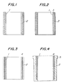
- 1 is a first ceramic member
- 2 is a second ceramic member
- 3 is a third ceramic member
- 4 is a lubricating layer
- 5 is a metallic member.
- Fig. 1 shows a schematic vertical sectional view of a cylinder of a reciprocating piston engine according to the invention.
- the wall of the cylinder is of a laminated structure having a first ceramic body 1 forming an inner layer with a front surface adapted to be in contact with hot gas and a second ceramic member 2 secured to rear or outer surface of the first ceramic member 1 and preferably made of the same material as that of the first ceramic member 1.
- the material of the first ceramic member 1 must have a mechanical strength of more than 20 kg/mm 2 , preferably more than 40 kg/mm 2 , more preferably more than 30 kg/mm 2 at 500°C, and examples of such material are zirconia, silicon nitride, sialon, silicon carbide, alumina, and the like.
- the laminated structure of Fig. 1 is formed most preferably by separately shaping and machining the first ceramic member 1 and the second ceramic member 2 so as to give them a thickness of more than 1 mm, preferably in a range of 2-10 mm, and then fitting the thus formed ceramic members one on the other.
- fitting here is to tightly combine two or more structural members into one body, and for instance, one member is fitted within and secured tightly to the other member by shrinkage fitting, pressure fitting or the like.
- the above-mentioned materials are preferable, because such ceramics as zirconia, silicon nitride, sialon, alumina, and the like have a small heat conductivity, more particularly less than one half of that of cast iron which is a typical metallic material of engine parts, so that such ceramic materials are twice suitable for the invention because the degree of heat insulation is inversely proportional to the heat conductivity.
- the above-referred ceramics have a melting point of above 1,900°C which represents a heat resistance of about twice as high as that of cast iron.
- silicon carbide is usable in the present invention because its melting point is as high as 2,700°C and it has a high mechanical strength at high temperatures.
- zirconia is the most preferable ceramics for the ceramic heat insulating layer in the engine part of the invention, because it has a very low heat conductivity of less than 0.01 cal/cm ⁇ sec ⁇ °C representing more than ten times of heat insulation compared to metallic materials, a melting point of 2,600°C representing excellent heat resistance, and a coefficient of thermal expansion of 10xlO- 6 / O C which is similar to that of cast iron so as to provide excellent mating with cast iron.
- Fig. 1 shows a cylinder made of only the first ceramic member 1 and the second ceramic member 2 combined in an overlaid or laminated way
- Fig. 2 uses a third ceramic member 3 which is disposed between the first ceramic member 1 with a front surface adapted to be in contact with hot gas and the second ceramic member 2 to be secured to the rear surface of the first ceramic member 1, so as to provide a more preferable structure capable of further reducing the thermal stress in the engine parts.
- the position of the third ceramic member 3 is not restricted to that between the first ceramic member 1 and the second ceramic member 2; namely, the third ceramic member 3 may be disposed on the opposite surface of the second ceramic member 2 to the first ceramic member 1.
- the third ceramic member 3 can be precoated on the inner surface of the metallic body as a ceramic lining layer thereon.
- more than three ceramic layers can be overlaid or laminated in the engine part according to the present invention.
- at least the first and second ceramic members 1 and 2 must have a mechanical strength of more than 20 kg/mm 2 , and the plurality of the ceramic members should preferably be made of the same material.
- a lubricating layer 4 can be inserted between the first ceramic member 1 adapted to be in contact with the inside hot gas and the second ceramic member 2 at the outer surface of the engine part, for the purpose of further reducing the thermal stress in the engine part.
- the lubricating member 4 can be made of a ceramics, a metal, or one or more of composite bodies of ceramics and metals.
- ceramics of the lubricating layer 4 ceramics with a high slidability such as boron nitride, talc, carbon, graphite, and the like are preferable, while preferable metal for the lubricating layer 4 is in the form of a plated layer or a vapour deposited layer of a metal with a high hardness such as nickel (Ni), chromium (Cr), or iron (Fe), a metal with a low melting point such as aluminium (A2) or copper (Cu), or an alloy thereof.
- Fig. 4 shows another preferred embodiment of the invention which has a metallic member 5 such as a metallic sleeve, and the overlaid or laminated ceramic members are fitted therein.
- a metallic member 5 such as a metallic sleeve
- the embodiment of Fig. 4 with a metallic sleeve or the like provides the engine part with a high mechanical strength.
- the engine part of the invention has an overlaid or laminated structure made of a plurality of ceramic members, so that the first ceramic member in contact with the high-temperature gas and the second ceramic member secured to the back surface thereof can slide relative to each other along the contact surface therebetween.
- the thermal stresses generated in the juxtaposed ceramic members do not affect each other, and the thermal stress caused in the low-temperature portion of the ceramic members can be suppressed, so as to improve the thermal shock resistance of the heat insulating ceramic members or layers and to prevent the ceramic members from being broken by the thermal stress.
- the adjacent ceramic members slide relative to each other with little friction and without restricted each other, and the lubricating layer inserted between the adjacent ceramic layers as shown in Figs. 3 and 4 is preferable because it enhances the sliding effects between the adjacent ceramic members.
- the lubricating layer 4 can be inserted between the metallic member 5 and the overlaid or laminated ceramic structure instead of the position of the embodiment of Fig. 4, and the same sliding effects are described above can be achieved with the thus inserted lubricating layer 4.
- the reason why the mechanical strength of the ceramic member is restricted to be more than 20 kg/mm 2 in the present invention is as follows; namely, if the mechanical strength is less than 20 kg/mm 2 , a large temperature difference cannot be achieved between a high-temperature portion and a low-temperature portion of the ceramic members without fracture of ceramic members by thermal stress even if the ceramic members are overlaid or laminated one on the other in the above-mentioned manner.
- the "mechanical strength” refers to the fracture stress when a four-point bending load is applied to a test piece of 3 mm thickness, 4 mm width, and 40 mm length with an external span of 30 mm and an internal span of 10 mm, as defined by the Japanese Industrial Standard JIS R1601 "Testing Method of Bending Strength of Fine Ceramics".
- First and second ceramic members were prepared by using ceramic materials with the mechanical strengths as shown in Table 1. After machining the thus prepared members, each of the second ceramic members was heated at 100°C for expansion, so as to fit the first ceramic member therein by shrinkage fitting. Whereby, samples No. 1 through No. 7 of the engine part of the invention were formed, which were cylinders with the overlaid or laminated structure. Some of the samples had lubricating layers inserted between the first ceramic member and the second ceramic member.
- the nickel lubricating layer In the case of the nickel lubricating layer, a nickel coating of 0.05 mm thickness was plated on the outer surface of the first ceramic member prior to the above-mentioned shrinkage fitting, while in the case of the talc or boron nitride lubricating layer, a 0.5 mm thick coating of the lubricating layer material was applied by brushing.
- the samples No. 1 through No. 5 were engine parts having cast iron sleeves with a wall thickness of 7 mm, and the two-ceramics-layer laminated structures were fitted in the cast iron sleeves by shrinkage fitting, while the samples No. 6 and No. 7 were engine parts made solely of the two-ceramics-layer structures.
- the engine parts thus prepared were assembled in Diesel engines, which were reciprocating piston engines, and the single-cylinder engine tests were carried out for 500 hours.
- sample No. 8 through No. 10 were prepared, which had a mechanical strength falling outside of the numerical limit of the present invention.
- Samples No. 11 and No. 12 having single-ceramic layer structures were also tested as examples of the prior art.
- Each of the samples No. 8 through No. 12 was an engine part having the ceramic members shrinkage fitted in a cast iron sleeve with a wall thickness of 7 mm. The result of the single-cylinder test is shown in Table 1.
- a zirconia plate with a mechanical strength of 60 kg/mm 2 was prepared as a first ceramic member to be in contact with hot gas, and the zirconia plate was machined into a disc with a diameter of 100 mm and a minimum thickness of 3 mm, which disc had a concave upper surface to be in contact with the hot gas and a flat lower surface not to be in contact with the hot gas.
- Second and third ceramic members were made from the same zirconia plate by machining it into discs having a diameter of 100 mm and a thickness of 2 mm with smooth upper and lower surfaces.
- the engine part of the present invention has an overlaid or laminated structure having a plurality of ceramic members with a high mechanical strength in excess of a specific value, e.g. 20 kg/mm 2 , and a first ceramic member to be in contact with hot gas and a low-temperature second ceramic member overlaid on the outer or back surface of the first ceramic member can slide relative to each other along the joint surface therebetween, whereby the thermal stress generated in the low-temperature second ceramic member can be reduced and the ceramics members are protected from breakage due to such thermal stress.
- a specific value e.g. 20 kg/mm 2
- the engine part of the invention greatly improves the thermal efficiency and effectively saves energy when they are used as cylinders, cylinder heads, pistons, precombustion chambers, port liners or the like in various reciprocating piston engines such as Diesel engines and spark ignition engines. Therefore, the engine part of the invention are very valuable from the standpoint of efficient use of energy.
Landscapes
- Engineering & Computer Science (AREA)
- General Engineering & Computer Science (AREA)
- Chemical & Material Sciences (AREA)
- Combustion & Propulsion (AREA)
- Mechanical Engineering (AREA)
- Ceramic Engineering (AREA)
- Cylinder Crankcases Of Internal Combustion Engines (AREA)
- Combustion Methods Of Internal-Combustion Engines (AREA)
- Pistons, Piston Rings, And Cylinders (AREA)
- Massaging Devices (AREA)
- Ceramic Products (AREA)
- Laminated Bodies (AREA)
- Valve Device For Special Equipments (AREA)
Priority Applications (1)
| Application Number | Priority Date | Filing Date | Title |
|---|---|---|---|
| AT83300053T ATE26742T1 (de) | 1982-10-25 | 1983-01-06 | Maschinenteil. |
Applications Claiming Priority (2)
| Application Number | Priority Date | Filing Date | Title |
|---|---|---|---|
| JP57186071A JPS5977062A (ja) | 1982-10-25 | 1982-10-25 | エンジン部品 |
| JP186071/82 | 1982-10-25 |
Publications (2)
| Publication Number | Publication Date |
|---|---|
| EP0110488A1 true EP0110488A1 (fr) | 1984-06-13 |
| EP0110488B1 EP0110488B1 (fr) | 1987-04-22 |
Family
ID=16181874
Family Applications (1)
| Application Number | Title | Priority Date | Filing Date |
|---|---|---|---|
| EP83300053A Expired EP0110488B1 (fr) | 1982-10-25 | 1983-01-06 | Elément de moteur |
Country Status (6)
| Country | Link |
|---|---|
| US (1) | US4600038A (fr) |
| EP (1) | EP0110488B1 (fr) |
| JP (1) | JPS5977062A (fr) |
| AT (1) | ATE26742T1 (fr) |
| CA (1) | CA1227387A (fr) |
| DE (1) | DE3371107D1 (fr) |
Cited By (2)
| Publication number | Priority date | Publication date | Assignee | Title |
|---|---|---|---|---|
| GB2204658A (en) * | 1987-05-16 | 1988-11-16 | Ae Plc | Cylinder liners |
| EP0426421A1 (fr) * | 1989-10-31 | 1991-05-08 | Inco Limited | Configuration d'un piston et cylindre à plusieurs métaux pour un moteur à combustion interne |
Families Citing this family (6)
| Publication number | Priority date | Publication date | Assignee | Title |
|---|---|---|---|---|
| JPH0536990Y2 (fr) * | 1987-02-23 | 1993-09-20 | ||
| US5284698A (en) * | 1991-09-18 | 1994-02-08 | Rockwell Int'l Corp. | Partially stabilized ZrO2 -based laminar ceramic composites |
| US6125891A (en) * | 1996-03-15 | 2000-10-03 | Silicon Carbide Products, Inc. | Refractory u-bends and methods of manufacture |
| DE102005013087B3 (de) * | 2005-03-18 | 2006-08-31 | Man B & W Diesel Ag | Kolben für eine Hubkolbenbrennkraftmaschine mit gehärteten Kolbenringnuten |
| JP2014095345A (ja) * | 2012-11-09 | 2014-05-22 | Isuzu Motors Ltd | 内燃機関 |
| GB2603961B (en) * | 2021-02-23 | 2023-05-03 | Aker Solutions As | Insulated fluid flow block |
Citations (3)
| Publication number | Priority date | Publication date | Assignee | Title |
|---|---|---|---|---|
| DE1955805A1 (de) * | 1969-11-06 | 1971-05-19 | Maschf Augsburg Nuernberg Ag | Zylinder mit trockener Zylinderlaufbuechse |
| EP0013599A1 (fr) * | 1979-01-04 | 1980-07-23 | Commonwealth Scientific And Industrial Research Organisation | Matériaux céramiques en zircone partiellement stabilisés; procédé pour leur fabrication, filières fabriquées à partir de ces matériaux, outils de coupe et poussoirs comportant un revêtement formé par ces matériaux |
| EP0036786A1 (fr) * | 1980-03-26 | 1981-09-30 | Ngk Insulators, Ltd. | Céramiques en zircone et procédé pour leur préparation |
Family Cites Families (15)
| Publication number | Priority date | Publication date | Assignee | Title |
|---|---|---|---|---|
| US1597249A (en) * | 1925-03-28 | 1926-08-24 | Orey L Riley | Cylinder liner |
| US1825678A (en) * | 1928-05-07 | 1931-10-06 | Thomas G Mcclatchey | Cylinder lining |
| US2198149A (en) * | 1937-08-03 | 1940-04-23 | Bangert Heinrich | Production of pipe conduits for chemical purposes |
| FR992440A (fr) * | 1948-08-16 | 1951-10-18 | Alliance Europ | Perfectionnements apportés aux moteurs à combustion interne |
| GB665330A (en) * | 1949-08-16 | 1952-01-23 | Alliance Europ | Improvements in or relating to the combustion chambers and pistons of internal combustion engines |
| US2745437A (en) * | 1951-09-12 | 1956-05-15 | Norton Co | Reinforced ceramic body of revolution |
| US3456690A (en) * | 1967-05-26 | 1969-07-22 | Vesuvius Crucible Co | Composite sleeve for ladle stopper rods |
| US3832273A (en) * | 1972-05-15 | 1974-08-27 | Carborundum Co | Composite refractory articles |
| JPS50131408U (fr) * | 1974-04-16 | 1975-10-29 | ||
| US4199010A (en) * | 1978-06-02 | 1980-04-22 | Foster Wheeler Energy Corporation | Ceramic lined conduit |
| JPS5635534U (fr) * | 1979-08-27 | 1981-04-06 | ||
| JPS6018621B2 (ja) * | 1981-05-21 | 1985-05-11 | 日本碍子株式会社 | エンジン部品 |
| JPS59101566A (ja) * | 1982-12-03 | 1984-06-12 | Ngk Insulators Ltd | エンジン部品 |
| JPS6018621A (ja) * | 1983-07-11 | 1985-01-30 | Ishikawajima Harima Heavy Ind Co Ltd | 撓み軸継手装置 |
| JPS621093A (ja) * | 1985-06-26 | 1987-01-07 | 沖電気工業株式会社 | 窓口取引装置 |
-
1982
- 1982-10-25 JP JP57186071A patent/JPS5977062A/ja active Granted
- 1982-12-27 US US06/452,969 patent/US4600038A/en not_active Expired - Lifetime
-
1983
- 1983-01-06 EP EP83300053A patent/EP0110488B1/fr not_active Expired
- 1983-01-06 DE DE8383300053T patent/DE3371107D1/de not_active Expired
- 1983-01-06 CA CA000419014A patent/CA1227387A/fr not_active Expired
- 1983-01-06 AT AT83300053T patent/ATE26742T1/de not_active IP Right Cessation
Patent Citations (3)
| Publication number | Priority date | Publication date | Assignee | Title |
|---|---|---|---|---|
| DE1955805A1 (de) * | 1969-11-06 | 1971-05-19 | Maschf Augsburg Nuernberg Ag | Zylinder mit trockener Zylinderlaufbuechse |
| EP0013599A1 (fr) * | 1979-01-04 | 1980-07-23 | Commonwealth Scientific And Industrial Research Organisation | Matériaux céramiques en zircone partiellement stabilisés; procédé pour leur fabrication, filières fabriquées à partir de ces matériaux, outils de coupe et poussoirs comportant un revêtement formé par ces matériaux |
| EP0036786A1 (fr) * | 1980-03-26 | 1981-09-30 | Ngk Insulators, Ltd. | Céramiques en zircone et procédé pour leur préparation |
Cited By (5)
| Publication number | Priority date | Publication date | Assignee | Title |
|---|---|---|---|---|
| GB2204658A (en) * | 1987-05-16 | 1988-11-16 | Ae Plc | Cylinder liners |
| EP0292040A3 (en) * | 1987-05-16 | 1989-09-20 | Ae Plc | Cylinder liners |
| US4921734A (en) * | 1987-05-16 | 1990-05-01 | Ae Plc | Cylinder liners |
| GB2204658B (en) * | 1987-05-16 | 1991-03-13 | Ae Plc | Cylinder liners |
| EP0426421A1 (fr) * | 1989-10-31 | 1991-05-08 | Inco Limited | Configuration d'un piston et cylindre à plusieurs métaux pour un moteur à combustion interne |
Also Published As
| Publication number | Publication date |
|---|---|
| JPS5977062A (ja) | 1984-05-02 |
| CA1227387A (fr) | 1987-09-29 |
| JPH0427379B2 (fr) | 1992-05-11 |
| EP0110488B1 (fr) | 1987-04-22 |
| ATE26742T1 (de) | 1987-05-15 |
| US4600038A (en) | 1986-07-15 |
| DE3371107D1 (en) | 1987-05-27 |
Similar Documents
| Publication | Publication Date | Title |
|---|---|---|
| US4242948A (en) | Insulated composite piston | |
| CA1202534A (fr) | Piece de moteur thermique | |
| EP0292040B1 (fr) | Chemise de cylindre | |
| EP0066022B1 (fr) | Eléments de moteur | |
| US4495684A (en) | Process of joining a ceramic insert which is adapted to be embedded in a light metal casting for use in internal combustion engines | |
| JPS5852451A (ja) | 耐熱・断熱性軽合金部材およびその製造方法 | |
| US4774926A (en) | Shielded insulation for combustion chamber | |
| US9447490B2 (en) | Piston ring | |
| US5660399A (en) | Piston rings particularly suited for use with ceramic matrix composite pistons and cylinders | |
| US5740788A (en) | Fiber reinforced ceramic matrix composite piston and cylinder/sleeve for an internal combustion engine | |
| EP0110488B1 (fr) | Elément de moteur | |
| EP0259023B1 (fr) | Sièges de soupape en céramique | |
| EP0155160A2 (fr) | Piston pour moteur à combustion interne et son procédé de fabrication | |
| EP0155159A2 (fr) | Piston pour moteur à combustion interne et son procédé de fabrication | |
| GB1577685A (en) | Insulated composite piston | |
| JPS5925058A (ja) | 内燃機関用シリンダ | |
| CA1272088A (fr) | Culasse en matiere ceramique pour moteur a combustion interne | |
| CA1078274A (fr) | Piston composite calorifuge | |
| EP0167528B1 (fr) | Culasse en ceramique pour moteur a combustion interne | |
| JPS60240855A (ja) | エンジン用断熱ピストン | |
| EP0468722A1 (fr) | Insert en céramique et métal | |
| JPS642778B2 (fr) | ||
| JPH1121679A (ja) | セラミックス断熱部材で被覆した機械構造部品 | |
| Matsuoka et al. | Development of ceramic pre–combustion chamber | |
| JPS63255552A (ja) | 断熱ピストンの構造 |
Legal Events
| Date | Code | Title | Description |
|---|---|---|---|
| PUAI | Public reference made under article 153(3) epc to a published international application that has entered the european phase |
Free format text: ORIGINAL CODE: 0009012 |
|
| 17P | Request for examination filed |
Effective date: 19830714 |
|
| AK | Designated contracting states |
Designated state(s): AT CH DE FR GB IT LI NL SE |
|
| GRAA | (expected) grant |
Free format text: ORIGINAL CODE: 0009210 |
|
| AK | Designated contracting states |
Kind code of ref document: B1 Designated state(s): AT CH DE FR GB IT LI NL SE |
|
| REF | Corresponds to: |
Ref document number: 26742 Country of ref document: AT Date of ref document: 19870515 Kind code of ref document: T |
|
| REF | Corresponds to: |
Ref document number: 3371107 Country of ref document: DE Date of ref document: 19870527 |
|
| ET | Fr: translation filed | ||
| ITF | It: translation for a ep patent filed | ||
| PLBI | Opposition filed |
Free format text: ORIGINAL CODE: 0009260 |
|
| 26 | Opposition filed |
Opponent name: MAN TECHNOLOGIE GMBH Effective date: 19880119 |
|
| NLR1 | Nl: opposition has been filed with the epo |
Opponent name: MAN TECHNOLOGIE GMBH |
|
| PLBN | Opposition rejected |
Free format text: ORIGINAL CODE: 0009273 |
|
| STAA | Information on the status of an ep patent application or granted ep patent |
Free format text: STATUS: OPPOSITION REJECTED |
|
| 27O | Opposition rejected |
Effective date: 19881229 |
|
| NLR2 | Nl: decision of opposition | ||
| ITTA | It: last paid annual fee | ||
| PGFP | Annual fee paid to national office [announced via postgrant information from national office to epo] |
Ref country code: GB Payment date: 19921224 Year of fee payment: 11 |
|
| PGFP | Annual fee paid to national office [announced via postgrant information from national office to epo] |
Ref country code: CH Payment date: 19930118 Year of fee payment: 11 |
|
| PGFP | Annual fee paid to national office [announced via postgrant information from national office to epo] |
Ref country code: FR Payment date: 19930119 Year of fee payment: 11 |
|
| PGFP | Annual fee paid to national office [announced via postgrant information from national office to epo] |
Ref country code: AT Payment date: 19930127 Year of fee payment: 11 |
|
| PGFP | Annual fee paid to national office [announced via postgrant information from national office to epo] |
Ref country code: NL Payment date: 19930131 Year of fee payment: 11 |
|
| PG25 | Lapsed in a contracting state [announced via postgrant information from national office to epo] |
Ref country code: GB Effective date: 19940106 Ref country code: AT Effective date: 19940106 |
|
| PGFP | Annual fee paid to national office [announced via postgrant information from national office to epo] |
Ref country code: SE Payment date: 19940119 Year of fee payment: 12 |
|
| PGFP | Annual fee paid to national office [announced via postgrant information from national office to epo] |
Ref country code: DE Payment date: 19940120 Year of fee payment: 12 |
|
| PG25 | Lapsed in a contracting state [announced via postgrant information from national office to epo] |
Ref country code: LI Effective date: 19940131 Ref country code: CH Effective date: 19940131 |
|
| PG25 | Lapsed in a contracting state [announced via postgrant information from national office to epo] |
Ref country code: NL Effective date: 19940801 |
|
| GBPC | Gb: european patent ceased through non-payment of renewal fee |
Effective date: 19940106 |
|
| NLV4 | Nl: lapsed or anulled due to non-payment of the annual fee | ||
| PG25 | Lapsed in a contracting state [announced via postgrant information from national office to epo] |
Ref country code: FR Effective date: 19940930 |
|
| REG | Reference to a national code |
Ref country code: CH Ref legal event code: PL |
|
| REG | Reference to a national code |
Ref country code: FR Ref legal event code: ST |
|
| PG25 | Lapsed in a contracting state [announced via postgrant information from national office to epo] |
Ref country code: SE Effective date: 19950107 |
|
| EAL | Se: european patent in force in sweden |
Ref document number: 83300053.2 |
|
| PG25 | Lapsed in a contracting state [announced via postgrant information from national office to epo] |
Ref country code: DE Effective date: 19951003 |
|
| EUG | Se: european patent has lapsed |
Ref document number: 83300053.2 |