EP0118806A1 - Bohrwerkzeug mit auswechselbarem Schneideinsatz - Google Patents
Bohrwerkzeug mit auswechselbarem Schneideinsatz Download PDFInfo
- Publication number
- EP0118806A1 EP0118806A1 EP84101764A EP84101764A EP0118806A1 EP 0118806 A1 EP0118806 A1 EP 0118806A1 EP 84101764 A EP84101764 A EP 84101764A EP 84101764 A EP84101764 A EP 84101764A EP 0118806 A1 EP0118806 A1 EP 0118806A1
- Authority
- EP
- European Patent Office
- Prior art keywords
- cutting
- cutting insert
- pin
- contact surfaces
- drilling tool
- Prior art date
- Legal status (The legal status is an assumption and is not a legal conclusion. Google has not performed a legal analysis and makes no representation as to the accuracy of the status listed.)
- Granted
Links
Images




Classifications
-
- B—PERFORMING OPERATIONS; TRANSPORTING
- B23—MACHINE TOOLS; METAL-WORKING NOT OTHERWISE PROVIDED FOR
- B23B—TURNING; BORING
- B23B51/00—Tools for drilling machines
- B23B51/04—Drills for trepanning
-
- B—PERFORMING OPERATIONS; TRANSPORTING
- B23—MACHINE TOOLS; METAL-WORKING NOT OTHERWISE PROVIDED FOR
- B23B—TURNING; BORING
- B23B51/00—Tools for drilling machines
-
- B—PERFORMING OPERATIONS; TRANSPORTING
- B23—MACHINE TOOLS; METAL-WORKING NOT OTHERWISE PROVIDED FOR
- B23B—TURNING; BORING
- B23B2251/00—Details of tools for drilling machines
- B23B2251/02—Connections between shanks and removable cutting heads
-
- B—PERFORMING OPERATIONS; TRANSPORTING
- B23—MACHINE TOOLS; METAL-WORKING NOT OTHERWISE PROVIDED FOR
- B23B—TURNING; BORING
- B23B2251/00—Details of tools for drilling machines
- B23B2251/14—Configuration of the cutting part, i.e. the main cutting edges
-
- B—PERFORMING OPERATIONS; TRANSPORTING
- B23—MACHINE TOOLS; METAL-WORKING NOT OTHERWISE PROVIDED FOR
- B23B—TURNING; BORING
- B23B2251/00—Details of tools for drilling machines
- B23B2251/20—Number of cutting edges
- B23B2251/201—Single cutting edge
-
- B—PERFORMING OPERATIONS; TRANSPORTING
- B23—MACHINE TOOLS; METAL-WORKING NOT OTHERWISE PROVIDED FOR
- B23B—TURNING; BORING
- B23B2251/00—Details of tools for drilling machines
- B23B2251/50—Drilling tools comprising cutting inserts
Definitions
- the invention relates to a drilling tool, which is composed of a tool shank with at least one flute and exchangeable cutting inserts.
- Known drilling tools of this type have a flat recess on the shaft tip in the wall of the flute for receiving the cutting insert, which is delimited by an edge on the shaft side.
- perforated inserts are inserted into the recess so that they rest with their shank-side narrow side on the shank-side edge of the recess and screwed tight with the aid of a screw which is passed through the hole in the insert (DE-OS 25 55 979).
- the object of the invention is to provide a drilling tool with an exchangeable cutting insert which is also suitable for small drilling cross sections and in which the cutting insert can be inserted and exchanged easily and quickly in the tool shank without additional fastening elements.
- the cutting insert on its shaft-side narrow side has a fastening pin concentric with the drill axis with lateral contact surfaces and can be inserted into the recess by a rotational movement against the direction of drilling and in that a receptacle concentric with the drill axis is provided in the shaft tip for the fastening pin is located with contact surfaces corresponding to the contact surfaces of the fastening pin.
- This cutting insert is inserted approximately from the center of the angle of the flute with the fastening pin into the pin receptacle and then rotated counter to the drilling direction until the cutting plates are inserted into the recesses in the wall of the flute.
- the contact surfaces of the fastening pin lie against the contact surfaces of the pin holder.
- the mounting pin can be tapered, cylindrical or dovetail-shaped.
- the pin holder of the tool shank has corresponding contact surfaces for each pin shape.
- the fastening pin is undercut in the pin circumference so that it can be inserted laterally into the pin receptacle from the flute; this undercut is not absolutely necessary for the conical fastening pin.
- the conical tapered mounting pin is self-locking in the pin holder with a suitable cone angle. This ensures that the cutting insert is secured in its seat so that it cannot fall out or be pulled out when the drill is withdrawn from the borehole.
- the conically tapered and the cylindrical fastening pin can also be widened at the end of the pin behind the contact surfaces.
- the pin receptacle for these mounting pins has a corresponding undercut on the inside behind the contact surfaces, in which the widening engages. This also secures the cutting insert against falling out or pulling out.
- the widening can be of any design. It can also serve to clamp the cutting insert with its shaft-side narrow side against the shaft-side edge of the recess. For this it is advantageous if the narrow side of the cutting insert and the edge of the recess only touch on the circumference of the drill and are spaced apart from one another towards the inside of the drill.
- the narrow side of the plate on the shaft side is likewise clamped against the edge of the recess on the shaft side, thereby securing the cutting insert in its seat.
- the narrow side of the plate and the edge of the recess only touch on the circumference of the drill and are spaced apart from one another in the inside of the drill.
- the shaft-side edge of the recess can rise slightly in the direction of insertion. This improves the tensioning of the cutting insert when screwing it into the insert seat.
- the same result can be achieved with the contact surfaces of the fastening pin and the pin receptacle rising slightly spirally in the direction of drilling and rotation.
- the drilling tool of this invention can have one or two major cutting edges.
- the double-edged drilling tool has two flutes, in the wall of which the two flat recesses for receiving the cutting inserts of the cutting insert are machined in a rotationally symmetrical manner.
- the receptacle for the fastening pin is located between the flutes.
- the uniform cutting insert has a two-leaf design and has two lateral, rotationally symmetrical cutting inserts, each starting from the drill axis, with one main cutting edge and the associated secondary cutting edges.
- the two cutting plates can be offset from one another by an angled center piece.
- the single-edged drilling tool has only one flute.
- the recess intended to receive the cutting insert merges towards the center of the drill into a cut hole which is concentric with the drill axis and whose wall can serve as a lateral contact surface for the cutting insert.
- the cutting insert has only one side cutting plate, starting from the drill axis, with a main cutting edge and the associated secondary cutting edges.
- the cutting insert can have a lateral contact surface on the opposite side of the drill axis.
- the side cutting plate can be angled against the center piece concentric with the drill axis.
- FIGS. 1 to 14 show different embodiments of the invention for double-edged drill tools.
- the basic shape of the cutting inserts for this drilling tool can be seen from FIGS. 1 and 2.
- the cutting insert (1) has two lateral cutting plates (3), each with a main cutting edge (4) and the associated secondary cutting edges. These inserts are arranged rotationally symmetrical to the drill axis (2).
- the fastening pin (5) is also located on the narrow side of the cutting insert opposite the drill tip, rotationally symmetrically to the drill axis (2).
- the arrow A indicates the direction of drilling. In Figure 1 you can see the cutting insert from the broad side. On the left panel, you can see the rake face (6), into which chip breakers can be molded as required.
- the fastening pin (5) has two lateral contact surfaces (11) that taper conically towards the pin end.
- Figure 3 shows the tool shank for this cutting insert.
- a flute 13
- the first flute in the left wall of the flute there is a recess for the left insert of the cutting insert with the rear wall (14) and the edge (15) on the shaft at the tip of the shaft.
- the second flute On the back of the tool shank is the second flute, in the wall of which the rotationally symmetrical opposite recess for the right cutting plate of the cutting insert is incorporated; this recess is shown in dashed lines.
- the receptacle (16) for the fastening pin (5) is located concentrically to the drill axis.
- the receptacle has the two lateral conical contact surfaces (17) which correspond in shape and size to the lateral contact surfaces (11) of the fastening pin.
- the cutting insert (1) is turned from above by an angle of approx. 45 ° against the rear wall of the recess - pushed into the pin receptacle with the fastening pin. Then it is rotated against the direction of rotation - in the direction of arrow B - until the rear sides (7) of the cutting plates lie against the rear walls (14) of the recesses (FIGS. 4 to 6). At the same time, the fastening pin is screwed into the pin receptacle in such a way that the conical contact surfaces (11) of the fastening pin lie against the conical contact surfaces (17) of the pin receptacle.
- the fastening pin is held in the pin receptacle in a self-locking manner. As a result, it cannot fall out or be pulled out when the drill is withdrawn from the borehole.
- the cone angle is drawn exaggerated in Figures 1 and 3 for reasons of illustration.
- the desired self-locking is obtained at cone angles between 2 ° and 22 °, preferably between 3 ° and 10 °.
- the fastening pin (5) is undercut in the pin circumference so that it can be better inserted into the pin receptacle and so that it does not hinder the chip drain.
- the undercut of the pin circumference is not absolutely necessary.
- Figures 7 and 8 show a drilling tool with another fastening pin (18).
- the conical widening (20) is located at the end of the spigot following the conically tapering contact surfaces (19).
- the pin receptacle (21) of the tool shank is tapered after the contact surfaces (22) at (23) in order to be able to accommodate the widening (20) at the end of the pin.
- the conical widening (20) secures the cutting insert against falling out or pulling out.
- the cutting insert has a fastening pin (24) with cylindrical contact surfaces (25) undercut in the pin circumference. Then there is a bead-shaped widening (26) at the end of the pin.
- the pin receptacle (27) has cylindrical contact surfaces (28) and then an undercut (29).
- the bead-shaped widening can lie snugly against the undercut and brace the shaft-side narrow side (30) of the cutting inserts against the shaft-side edge (31) of the recess. This ensures that the cutting insert is held securely in the tool shank and secured against falling out or being pulled out. This tensioning and securing of the cutting insert is improved if the narrow side (30) and the edge (31) only touch on the circumference of the drill and run at a distance from one another towards the inside of the drill (FIG. 11).
- FIGS. 15 to 20 show an embodiment for a single-edged drilling tool according to this invention.
- the cutting insert (38) has only one cutting plate (39) with a main cutting edge (41) which extends laterally from the drill axis (40).
- the cutting insert has a lateral contact surface (45) on the other side of the drill axis (40).
- the "middle piece” (46) can be angled against the cutting plate (39), so that the cutting insert is better supported in its seat.
- the fastening pin (47) is dovetail-shaped with lateral contact surfaces (48). Likewise, all other fastening pins and associated pin receptacles, which were described in this application for the double-edged drilling tool, can also be used for the cutting insert of the single-edged drilling tool.
- the tool shank (49) has only a single flute (50), in the wall of which the recess for the cutting plate (39) of the cutting insert is located at the shank tip, with a rear wall (51) and the shank-side edge (52).
- the recess goes towards the center of the drill into the central bore (53), the wall of which acts as a lateral support surface for the lateral contact surface (45).
- the cutting insert can serve.
- the concentric pin receptacle (54) is located inside the bore.
- their lateral contact surfaces (55) are also conical, corresponding to the contact surfaces (48) of the fastening pin.
- the cutting insert of the single-edged drilling tool is inserted into the tool shaft from the center of the flute (50) in the same way as the cutting insert of the double-edged drilling tool and is fixed by turning against the direction of rotation (in the direction of arrow B).
Landscapes
- Engineering & Computer Science (AREA)
- Mechanical Engineering (AREA)
- Drilling Tools (AREA)
- Earth Drilling (AREA)
- Drilling And Exploitation, And Mining Machines And Methods (AREA)
Abstract
Description
- Die Erfindung bezieht sich auf ein Bohrwerkzeug, welches aus einem Werkzeugschaft mit mindestens einer Spannut und auswechselbaren Schneideinsätzen zusammengesetzt ist.
- Bekannte Bohrwerkzeuge dieser Art haben an der Schaftspitze in der Wand der Spannut eine flache Ausnehmung zur Aufnahme des Schneideinsatzes, die zur Schaftseite hin durch einen Rand begrenzt ist. Als auswechselbare Schneideinsätze werden gelochte Wendeschneidplatten in die Ausnehmung so eingesetzt, daß sie mit ihrer schaftseitigen Schmalseite am schaftseitigen Rand der Ausnehmung anliegen und mit Hilfe einer Schraube festgeschraubt, die durch das Loch der Wendeschneidplatte hindurchgeführt wird (DE-OS 25 55 979).
- Bei diesen Bohrwerkzeugen kann ein gewisser Mindest-Bohrquerschnitt nicht unterschritten werden, weil gelochte Wendeschneidplatten und andere Hartmetall-Lochplatten nicht unter einer gewissen Größe gefertigt werden können und weil außerdem die Befestigungsschrauben wegen der Beanspruchungen beim Bohren eine gewisse Mindeststärke haben müssen und schließlich das stützende Material des Bohrerschaftes hinter der Wendeschneidplatte eine gewisse Stärke besitzen muß, damit die Befestigungsschraube und auch die Schneidplatte noch genügend Halt finden. Nachteilig ist ferner, daß zur Befestigung der Wendeschneidplatte eine Befestigungsschraube als zusätzliches Befestigungselement verwendet wird. Das Auswechseln der Schneideinsätze ist dadurch umständlich und zeitraubend.
- Die Erfindung hat die Aufgabe, ein Bohrwerkzeug mit auswechselbarem Schneideinsatz zur Verfügung zu stellen,welches auch für kleine Bohrquerschnitte geeignet ist und bei welchem der Schneideinsatz ohne zusätzliche Befestigungselemente einfach und schnell in den Werkzkeugschaft eingesetzt und ausgewechselt werden kann.
- Diese Aufgabe wird dadurch gelöst, daß der Schneideinsatz an seiner schaftseitigen Schmalseite einen zur Bohrerachse konzentrischen Befestigungszapfen mit seitlichen Anlageflächen besitzt und durch eine Drehbewegung gegen den Bohr-Drehsinn in die Ausnehmung einsetzbar ist und daß sich in der Schaftspitze eine zur Bohrerachse konzentrische Aufnahme für den Befestigungszapfen befindet mit Anlageflächen entsprechend zu den Anlageflächen des Befestigungszapfens.
- Dieser Schneideinsatz wird etwa von der Winkelmitte der Spannut her mit dem Befestigungszapfen in die Zapfenaufnahme eingesetzt und dann gegen den Bohr-Drehsinn verdreht, bis die Schneidplatten in die Ausnehmungen in der Wand der Spannut eingefügt sind. Dabei legen sich Anlageflächen des Befestigungszapfens an die Anlageflächen der Zapfenaufnahme an. Beim Bohren wird der Schneideinsatz durch den Befestigungszapfen konzentrisch gehalten. Gegen die Schnittkräfte wird er durch die Hinterwand und den schaftseitigen Rand der Ausnehmung abgestützt. Die Schnittkräfte drücken dabei den Schneideinsatz in seinen Sitz hinein, so daß er gegen alle Beanspruchungen der Bohrarbeit auch ohne zusätzliche Befestigungsmittel absolut fest und sicher sitzt.
- Der Befestigungszapfen kann konisch verjüngt, zylindrisch oder schwalbenschwanzförmig ausgebildet sein. Die Zapfenaufnahme des Werkzeugschaftes hat für jede Zapfenform entsprechende Anlageflächen. Der Befestigungszapfen ist im Zapfenumfang hinterschnitten, damit er von der Spannut her seitlich in die Zapfenaufnahme eingesetzt werden kann; bei dem konischen Befestigungszapfen ist diese Hinterschneidung nicht unbedingt erforderlich.
- Der konich verjüngte Befestigungszapfen setzt sich bei geeignetem Konuswinkel selbsthemmend in der Zapfenaufnahme fest. Dadurch wird der Schneideinsatz in seinem Sitz gesichert, daß er nicht herausfallen oder herausgezogen werden kann, wenn der Bohrer aus dem Bohrloch zurückgezogen wird.
- Der konisch verjüngte und der zylindrische Befestigungszapfen können ferner am Zapfenende hinter den Anlageflächen verbreitert sein. Die Zapfenaufnahme für diese Befestigungszapfen hat im Inneren hinter den Anlageflächen eine entsprechende Hinterschneidung, in welche die Verbreiterung eingreift. Das sichert den Schneideinsatz ebenfalls gegen ein Herausfallen oder Herausziehen. Die Verbreiterung kann beliebig ausgebildet sein. Sie kann auch dazu dienen, den Schneideinsatz mit seiner schaftseitigen Schmalseite gegen den schaftseitigen Rand der Ausnehmung zu verspannen. Dafür ist es vorteilhaft, wenn sich die Schmalseite des Schneideinsatzes und der Rand der Ausnehmung nur am Bohrerumfang berühren und zum Bohrerinnern hin im Abstand voneinander verlaufen.
- Bei einem Schneideinsatz mit schwalbenschwanzförmigem Befestigungszapfen wird die schaftseitige Plattenschmalseite ebenfalls gegen den schaftseitigen Rand der Ausnehmung verspannt und dadurch der Schneideinsatz in seinem Sitz gesichert. Auch hier ist es zweckmäßig, wenn sich die Plattenschmalseite und der Rand der Ausnehmunghur am Bohrerumfang berühren und im Bohrerinnern im Abstand voneinander verlaufen. Ferner kann der schaftseitige Rand der Ausnehmung in Eindrehrichtung leicht ansteigen. Damit wird die Verspannung des Schneideinsatzes beim Eindrehen in den Plattensitz verbessert. Dasselbe Ergebnis erzielt man mit leicht spiralig im Bohr-Drehsinn ansteigenden Anlageflächen des Befestigungszapfens und der Zapfenaufnahme.
- Das Bohrwerkzeug dieser Erfindung kann eine oder zwei Hauptschneiden haben.
- Das zweischneidige Bohrwerkzeug hat zwei Spannuten, in deren Wand an der Schaftspitze die beiden flachen'Ausnehmungen für die Aufnahme der Schneidplatten des Schneideinsatzes rotationssymmetrisch eingearbeitet sind. Zwischen den Spannuten befindet sich die Aufnahme für den Befestigungszapfen. Der einheitliche Schneideinsatz ist zweiflü_glig ausgebildet und hat zwei seitliche, von der Bohrerachse ausgehende rotationssymmetrische Schneidplatten mit je einer Hauptschneide und den zugehörigen Nebenschneiden. Die beiden Schneidplatten können durch ein abgewinkeltes Mittelstück gegeneinander versetzt sein.
- Das einschneidige Bohrwerkzeug hat nur eine Spannut. Die zur Aufnahme des Schneideinsatzes bestimmte Ausnehmung geht zur Bohrermitte hin in eine zur Bohrerachse konzentrische, angeschnittene Bohrung über, deren Wand als seitliche Anlagefläche für den Schneideinsatz dienen kann. Der Schneideinsatz hat nur eine seitliche, von der Bohrerachse ausgehende Schneidplatte mit einer Hauptschneide und den zugehörigen Nebenschneiden. Auf der gegenüberliegenden Seite der Bohrerachse kann der Schneideinsatz eine seitliche Anlagefläche haben. Die seitliche Schneidplatte kann gegen das zur Bohrerachse konzentrische Mittelstück abgewinkelt sein.
-
- Figur 1 zeigt einen Schneideinsatz für ein zweischneidiges Bohrwerkzeug mit konisch verjüngtem Befestigungszapfen.
- Figur 2 zeigt den Schneideinsatz nach Figur 1 von oben.
- Figur 3 zeigt die Schaftspitze für den Schneideinsatz nach Figur 1.
- Figur 4 zeigt in Draufsicht, wie der Schneideinsatz aus Figur 1 in die Schaftspitze aus Figur 3 eingesetzt wird.
- Figur 5 zeigt die Schaftspitze mit eingesetztem Schneideinsatz von oben.
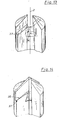
- Figur 6 zeigt die Schaftspitze mit eingesetztem Schneideinsatz in perspektivischer Darstellung.
- Figur 7 zeigt einen Schneideinsatz mit konisch verjüngendem Befestigungszpafen, bei welchem sich das Zapfenende im Anschluß an die Anlageflächen konisch verbreitert.
- Figur 8 zeigt die Schaftspitze für den Befestigungszapfen nach Figur 7.
- Figur 9 zeigt einen Schneideinsatz mit zylindrischen Anlageflächen und daran anschließend einer wulstförmigen Verbreiterung.
- Figur 10 zeigt die Schaftspitze für den Schneideinsatz nach Figur 9.
- Figur 11 zeigt die Schaftspitze nach Figur 10 mit eingesetztem Schneideinsatz.
- Figur 12 zeigt einen Schneideinsatz mit schwalbenschwanzförmigem Befestigungszapfen.
- Figur 13 zeigt die Schaftspitze für den Schneideinsatz nach Figur 12.
- Figur 14 zeigt die Schaftspitze nach Figur 13 mit eingesetztem Schneideinsatz.
- Figur 15 zeigt einen Schneideinsatz für ein einschneidiges Bohrwerkzeug.
- Figur 16 zeigt den Schneideinsatz nach Figur 15 von oben.
- Figur 17 zeigt die Schaftspitez für den Schneideinsatz nach Figur 15.
- Figur 18 zeigt in Draufsicht, wie der Schneideinsatz nach Figur 15 in die Schaftspitze nach Figur 17 eingesetzt wird.
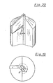
- Figur 19 zeigt die Schaftspitze nach Figur 17 mit eingesetztem Schneideinsatz von oben.
- Figur 20 zeigt die Schaftspitze nach Figur 17 mit eingesetztem Schneideinsatz in perspektivischer Darstellung.
- In Figuren 1 bis 14 sind verschiedene Ausführungsormen der Erfindung für zweischneidige Bohrerwerkzeuge dargestellt. Die Grundform der Schneideinsätze für dieses Bohrwerkzeug ist aus Figuren 1 und 2 erkennbar. Der Schneideinsatz (1) hat zwei seitliche Schneidplatten (3) mit je einer Hauptschneide (4) und den zugehörigen Nebenschneiden. Diese Schneidplatten sind zur Bohrerachse (2) rotationssymmetrisch angeordnet. An der Schmalseite des Schneideinsatzes gegenüber der Bohrerspitze befindet sich ebenfalls rotationssymeetrisch zur Bohrerachse (2) der Befestigungszapfen (5). Der Pfeil A gibt den Bohr-Drehsinn an. In Figur 1 sieht man den Schneideinsatz von der Breitseite. Bei der linken Platte blickt man auf die Spanfläche (6), in die nach Bedarf Spanleitstufen eingeformt werden können. Bei der rechten Platte blickt man auf die Rückseite (17), welche im eingesetzten Zustand gegen die Hinterwand (14) der Ausnehmung in der Wand der Spannut anliegt,Außerdem erkennt man bei der rechten Platte die Freifläche (9) der Hauptschneide und die Freifläche (10) der Nebenschneide. Die beiden Schneidplatten sind durch ein abgewinkeltes Mittelstück gegeneinander versetzt, dessen Außenfläche (8) den Übergang von der Spanfläche der linken Platte zur Rückseite der rechten Platte bildet. Der Befestigungszapfen (5) hat bei dieser Ausführungsform zwei konisch zum Zapfenende hin verjüngende seitliche Anlageflächen (11).
- Figur 3 zeigt den Werkzeugschaft für diesen Schneideinsatz. Man blickt in eine Spannut (13). In der linken Wand der Spannut befindet sich an der Schaftspitze die Ausnehmung für die linke Schneidplatte des Schneideinsatzes mit der Hinterwand (14) und dem schaftseitigen Rand (15). Auf der Rückseite des Werkzeugschaftes befindet sich die zweite Spannut, in deren Wand die rotationssymmetrisch gegenüberliegende Ausnehmung für die rechte Schneidplatte des Schneideinsatzes eingearbeitet ist; diese Ausnehmung ist gestrichelt gezeichnet. Zwischen den Spannuten und den Ausnehmungen befindet sich konzentrisch zur Bohrerachse die Aufnahme (16) für den Befestigungszapfen (5). Die Aufnahme hat die beiden seitlichen konischen Anlageflächen (17), die nach Form und Größe den seitlichen Anlageflächen (11) des Befestigungszapfens entsprechen.
- Zum Einsetzen wird der Schneideinsatz (1) von oben-um einen Win - kel von ca. 45° gegen die Rückwand der Ausnehmung verdreht - mit dem Befestigungszapfen in die Zapfenaufnahme hineingeschoben. Anschließend wird er gegen den Bohr-Drehsinn - in Richtung des Pfeiles B - verdreht, bis die Rückseiten (7) der Schneidplatten an die Hinterwände (14) der Ausnehmungen anliegen (Figuren 4 bis 6). Dabei wird gleichzeitig der Befestigungszapfen so in die Zapfenaufnahme hineingedreht, daß die konischen Anlageflächen (11) des Befestigungszapfens gegen die konischen Anlageflächen (17) der Zapfenaufnahme anliegen. Aufgrund der Keilwirkung und der Reibungskräfte zwichen diesen kOnSchen Anlageflächen wird der Befestigungszapfen selbsthemmend in der Zapfenaufnahme festgehalten. Dadurch kann er weder herausfallen noch herausgezogen werden, wenn der Bohrer aus dem Bohrloch zurückgezogen wird. Der Konuswinkel ist in den Figuren 1 und 3 aus Gründen der Darstellung übertrieben groß gezeichnet. Beispielsweise für einen Werkzeugschaft aus Stahl und Schneideinsätze aus Hartmetall erhält man die gewünschte Selbsthemmung bei Konuswinkeln zwischen 2° und 22°, vorzugsweise zwischen 3° und 10°.
- Der Befestigungszapfen (5) ist im Zapfenumfang hinterschnitten, damit er besser in die Zapfenaufnahme eingeschoben werden kann und damit er den Spanabfluß nicht behindert. Bei dem konisch verjüngten Befestigungszapfen dieser Ausführungsform ist die Hinterschneidung des Zapfenumfangs nicht unbedingt notwendig.
- Figuren 7 und 8 zeigen ein Bohrwerkzeug mit einem anderen Befestigungszapfen (18). Am Zapfenende befindet sich im Anschluß an die konisch sich verjüngenden Anlageflächen (19) die konische Verbreiterung (20). Die Zapfenaufnahme (21) des Werkzeugschaftes ist im Anschluß an die Anlageflächen (22) bei (23) konisch hin- terschnitten, um die Verbreiterung (20) am Zapfenende aufnehmen zu können. Die konische Verbreiterung (20) sichert den Schneideinsatz gegen ein Herausfallen oder Herausziehen.
- Bei der Ausführungsform nach Figuren 9 bis 11 hat der Schneideinsatz einen Befestigungszapfen (24) mit zylindrischen, im Zapfenumfang hinterschnittenen Anlageflächen (25). Daran anschließend befindet sich am Zapfenende eine wulstförmige Verbreiterung (26). Die Zapfenaufnahme (27) hat zylindrische Anlageflächen (28) und daran anschließend eine Hinterschneidung (29). Die wulstförmige Verbreiterung kann satt an der Hinterschneidung anliegen und die schaftseitige Schmalseite (30) der Schneidplatten gegen den schaftseitigen Rand (31) der Ausnehmung verspannen. Dadurch wird der Schneideinsatz im Werkzeugschaft absolut sicher festgesetzt und gegen ein Herausfallen bzw. Herausziehen gesichert. Diese Verspannung und Sicherung des Schneideinsatzes wird verbessert, wenn sich die Schmalseite (30) und der Rand (31) nur am Bohrerumfang berühren und zum Bohrerinnern hin im Abstand voneinander verlaufen (Figur 11).
- In der Ausführungsform nach Figuren 12 bis 14 ist der Befestiguhgszapfen (32) schwalbenschwanzförmig ausgebildet mit konsch°n, im Zapfenumfang hinterschnittenen Anlageflächen (33).Die Zapfenaufnahme (34) hat entsprechende konische Anlageflächen (35). Der eingesetzte Befestigungszapfen verspannt die schaftseitige Schmalseite (36) der Schneidplatten gegen den schaftseitigen Rand (37) der Ausnehmung im Werkzeugschaft und sichert so den Halt des Schneideinsatzes. Auch hier wird der Halt verbessert, wenn sich die Schmalseite (36) und der Rand (37) nur am Bohrerumfang berühren und zum Bohrerinnern hin im Abstand voneinander verlaufen. Ferner kann der schaftseitige Rand der Ausnehmung in Eindrehrichtung leicht ansteigen. Damit wird die Verspannung des Schneideinsatzes beim Eindrehen in den Plattensitz verstärkt. Dasselbe Ergebnis erzielt man, wenn die Anlageflächen (33) des Befestigungszapfens und (35) der Zapfenaufnahme in angenäherter Konusform so ausgebildet werden, daß sie leicht spiralig im Bohr-Drehsinn ansteigen.
- Figuren 15 bis 20 zeigen ein Ausführungsbeispiel für ein einschneidiges Bohrwerkzeug nach dieser Erfindung. Der Schneideinsatz (38) hat nur eine Schneidplatte (39) mit einer Hauptschneide (41), die seitlich von der Bohrerachse (40) ausgeht.
- In Figur 15 blickt man auf die Rückseite (42) der Schneidplatte (39) und erkennt außerdem die Freifläche (43) der Hauptschneide und.der Freifläche (44) der Nebenschneide. Gegenüber der Schneidplatte hat der Schneideinsatz auf der anderen Seite der Bohrerachse (40) eine seitliche Anlagefläche (45). Dabei kann das "Mittelstück" (46) gegen die Schneidplatte (39) abgewinkelt sein,,damit der Schneideinsatz in seinem Sitz besser abgestützt wird. Bei der abgebildeten Ausführungsform ist der Befestigungszapfen (47) schwalbenschwanzförmig mit seitlichen Anlageflächen (48). Ebenso können für den Schneideinsatz des einschneidigen Bohrwerkzeuges auch alle anderen Befestigungszapfen und zugehörigen Zapfenaufnahmen verwendet werden, die in dieser Anmeldung für das zweischneidige Bohrwerkzeug beschrieben wurden.
- Der Werkzeugschaft (49) hat nur eine einzige Spannut (50), in deren Wand an der Schaftspitze sich die Ausnehmung für die Schneidplatte (39) des Schneideinsatzes befindet mit einer Rückwand (51) und dem schaftseitigen Rand (52). Die Ausnehmung geht zur Bohrermitte hin in die zentrale Bohrung (53) über, deren Wand als seitliche Stützfläche für die seitliche Anlagefläche (45) des Schneideinsatzes dienen kann. Im Inneren der Bohrung befindet sich die konzentrische Zapfenaufnahme (54). Ihre seitlichen Anlageflächen (55) sind bei diesem Ausführungsbeispiel entsprechend den Anlageflächen (48) des Befestigungszapfens ebenfalls konisch ausgebildet. Der Schneideinsatz des einschneidigen Bohrwerkzeuges wird in der gleichen Weise wie der Schneideinsatz des zweischneidigen Bohrwerkzeuges von der Mitte der Spannut (50) her in den Werkzeugschaft eingesetzt und durch eine Drehung gegen den Bohr-Drehsinn (in Richtung des Pfeiles B) festgesetzt.
Claims (24)
dadurch gekennzeichnet, daß
Priority Applications (1)
| Application Number | Priority Date | Filing Date | Title |
|---|---|---|---|
| AT84101764T ATE31041T1 (de) | 1983-02-23 | 1984-02-21 | Bohrwerkzeug mit auswechselbarem schneideinsatz. |
Applications Claiming Priority (2)
| Application Number | Priority Date | Filing Date | Title |
|---|---|---|---|
| DE3306209 | 1983-02-23 | ||
| DE3306209A DE3306209C2 (de) | 1983-02-23 | 1983-02-23 | Bohrwerkzeug mit auswechselbarem Schneideinsatz |
Publications (2)
| Publication Number | Publication Date |
|---|---|
| EP0118806A1 true EP0118806A1 (de) | 1984-09-19 |
| EP0118806B1 EP0118806B1 (de) | 1987-11-25 |
Family
ID=6191567
Family Applications (1)
| Application Number | Title | Priority Date | Filing Date |
|---|---|---|---|
| EP84101764A Expired EP0118806B1 (de) | 1983-02-23 | 1984-02-21 | Bohrwerkzeug mit auswechselbarem Schneideinsatz |
Country Status (4)
| Country | Link |
|---|---|
| EP (1) | EP0118806B1 (de) |
| AT (1) | ATE31041T1 (de) |
| DE (2) | DE3306209C2 (de) |
| WO (1) | WO1984003241A1 (de) |
Cited By (35)
| Publication number | Priority date | Publication date | Assignee | Title |
|---|---|---|---|---|
| EP0441302A3 (en) * | 1990-02-05 | 1992-01-15 | Sumitomo Electric Industries, Ltd. | Throw-away tipped drill |
| EP0443517A3 (en) * | 1990-02-20 | 1992-02-12 | Sumitomo Electric Industries, Ltd. | Throw-away tipped drill |
| US5228812A (en) * | 1989-12-25 | 1993-07-20 | Sumitomo Electric Industries, Ltd. | Throw-away tipped drill |
| US5338135A (en) * | 1991-04-11 | 1994-08-16 | Sumitomo Electric Industries, Ltd. | Drill and lock screw employed for fastening the same |
| WO1995005262A1 (en) * | 1993-08-19 | 1995-02-23 | Jones Drilling Services Limited | Drill bit |
| US5697738A (en) * | 1994-12-30 | 1997-12-16 | Black & Decker, Inc. | Spade-type boring bit having chamfered corner portions |
| US5842267A (en) * | 1994-12-30 | 1998-12-01 | Black & Decker, Inc. | Method and apparatus for forming parts of a predetermined shape from a continuous stock material |
| RU2136451C1 (ru) * | 1994-10-07 | 1999-09-10 | Кеннаметал Хертель АГ Веркцойге + Хартштоффе | Сверло с режущей пластиной |
| US5957631A (en) * | 1997-05-29 | 1999-09-28 | Iscar Ltd. | Cutting tool assembly and a replaceable cutting head for use therein |
| US5971673A (en) * | 1996-09-13 | 1999-10-26 | Seco Tools Ab | Two-piece rotary metal-cutting tool and method for interconnecting the pieces |
| DE19834635A1 (de) * | 1998-07-31 | 2000-02-10 | Guehring Ohg | Bohrwerkzeug mit einem gegen Lösen gesicherten, austauschbaren Schneideinsatz |
| WO2000009282A1 (en) * | 1998-08-13 | 2000-02-24 | Iscar Ltd. | Cutting head and tool holder coupling |
| US6109841A (en) * | 1995-11-07 | 2000-08-29 | Johne & Co., Prazisionswerkzeuge GmbH | Drilling tool with replaceable bit |
| WO2002002263A1 (en) * | 2000-07-06 | 2002-01-10 | Sandvik Ab | Rotatable tool having a replaceable tip at the chip removing free end of the tool |
| US6481938B2 (en) * | 2000-03-17 | 2002-11-19 | Sandvik Ab | Drilling tool including a shank and a cutting body detachably secured thereto |
| US6485235B1 (en) | 2001-05-08 | 2002-11-26 | Allied Machine & Engineering Corp. | Cutting tool assembly with replaceable cutting head |
| WO2003070408A1 (de) * | 2002-02-21 | 2003-08-28 | Kennametal Inc. | Rundlaufschneidwerkzeug mit auswechselbarem schneideinsatz |
| WO2003025486A3 (en) * | 2001-09-14 | 2003-10-16 | Jakobus Lewis | Furnace taphole drill |
| US7070367B2 (en) | 1999-08-03 | 2006-07-04 | Kennametal Inc. | Twist drill for drilling having a replaceable drill tip, and a replaceable drill tip for use in a twist drill |
| US7309196B2 (en) | 2004-10-05 | 2007-12-18 | Kennametal Inc. | Modular drill |
| CN101927372A (zh) * | 2009-06-23 | 2010-12-29 | 山特维克知识产权股份有限公司 | 松顶部式钻削刀具 |
| WO2011055372A3 (en) * | 2009-11-09 | 2011-09-15 | No Screw Ltd. | Cutting tool, cutting tool holder, and a cutting insert therefor |
| GB2480022A (en) * | 2006-03-02 | 2011-11-02 | Milwaukee Electric Tool Corp | Cutting tool comprising removable blade with first and second cutting edges |
| GB2483008A (en) * | 2006-03-02 | 2012-02-22 | Milwaukee Electric Tool Corp | Removable cutting blade comprising locking surface between first and second cutting edges |
| US9162295B2 (en) | 2010-03-26 | 2015-10-20 | Sandvik Intellectual Property Ab | Rotatable tool for chip removing machining as well as a loose top and a basic body therefor |
| EP2111319B1 (de) | 2007-02-12 | 2016-06-15 | Iscar Ltd. | Werkzeug mit lösbar befestigtem selbstklemmschneidkopf |
| EP2276598A4 (de) * | 2008-04-14 | 2017-05-10 | Seco Tools AB | Werkzeug, werkzeugkörper und schneidekopf |
| EP3427877A1 (de) * | 2017-07-10 | 2019-01-16 | Sandvik Intellectual Property AB | Rotierender schneideinsatz und werkzeug mit deklinierten axialabstützungsflächen |
| US10532412B2 (en) | 2016-09-23 | 2020-01-14 | Milwaukee Electric Tool Corporation | Hole saw arbor assembly |
| US10618119B2 (en) | 2006-03-02 | 2020-04-14 | Milwaukee Electric Tool Corporation | Cutting tool |
| US10730119B2 (en) | 2017-01-06 | 2020-08-04 | Milwaukee Electric Tool Corporation | Hole saw |
| US20220118530A1 (en) * | 2018-02-02 | 2022-04-21 | J.H. Fletcher & Co. | Quick-release coupling for drilling and related methods |
| USD965653S1 (en) | 2017-08-15 | 2022-10-04 | Milwaukee Electric Tool Corporation | Hole saw |
| US11911830B2 (en) | 2019-06-13 | 2024-02-27 | Kennametal India Ltd. | Indexable drilling inserts |
| US12472566B2 (en) | 2021-08-17 | 2025-11-18 | Kennametal India Ltd. | Indexable drill assembly with coolant system |
Families Citing this family (33)
| Publication number | Priority date | Publication date | Assignee | Title |
|---|---|---|---|---|
| DE3610016A1 (de) * | 1986-03-25 | 1987-10-01 | Guenther Dr Hartner | Stufenbohrer |
| SE461024B (sv) * | 1988-06-23 | 1989-12-18 | Sandvik Ab | Borr |
| SE467727B (sv) * | 1991-01-28 | 1992-09-07 | Sandvik Ab | Borr med minst tvaa skaer, samt med symmetrisk borrspets och olika laanga skaereggar |
| DE4239257C2 (de) * | 1992-11-21 | 1998-02-26 | Mapal Fab Praezision | Spitzbohrwerkzeug |
| DE4239311C2 (de) * | 1992-11-23 | 1996-04-18 | Guehring Joerg Dr | Bohrer, insbesondere Spitzbohrwerkzeug mit austauschbarem Schneideinsatz |
| USD372485S (en) | 1994-12-30 | 1996-08-06 | Black & Decker, Inc. | Spade-type boring bit |
| US6290439B1 (en) | 1994-12-30 | 2001-09-18 | Black & Decker, Inc. | Method and apparatus for forming parts from a continuous stock material and associated forge |
| USD376809S (en) | 1995-11-07 | 1996-12-24 | Black & Decker Inc. | Spade-type boring bit |
| USD394663S (en) | 1996-03-25 | 1998-05-26 | Black & Decker Inc. | Spade-type boring bit having chamfered corner portions |
| DE10042990A1 (de) * | 2000-09-01 | 2002-03-28 | Kennametal Inc | Rundlauf-Schneidwerkzeug, z. B. Bohrer |
| JP2002096211A (ja) * | 2000-09-14 | 2002-04-02 | Sumitomo Electric Ind Ltd | スローアウェイ式ドリル |
| IL181296A0 (en) * | 2007-02-12 | 2007-07-04 | Iscar Ltd | Tool with releasably mounted self-clamping cutting head |
| FR2916150B1 (fr) * | 2007-05-16 | 2009-07-31 | Safety Production Soc Par Acti | Porte-outil et plaquette de coupe a nez de centrage |
| DE102007050471A1 (de) | 2007-10-23 | 2009-04-30 | MAPAL Fabrik für Präzisionswerkzeuge Dr. Kress KG | Werkzeug zur spanenden Bearbeitung von Werkstücken |
| FR2943565B1 (fr) * | 2009-03-27 | 2012-12-28 | Diager | Plaquette de coupe pour outil rotatif de percage |
| US9010464B2 (en) * | 2011-05-04 | 2015-04-21 | Dover BMCS Acquistion Corporation | Drill bits and drilling apparatuses including the same |
| DE102011051374B4 (de) | 2011-06-27 | 2021-08-26 | Gühring KG | Wechselplatten-Bohrwerkzeug |
| CN205218137U (zh) | 2013-02-01 | 2016-05-11 | 米沃奇电动工具公司 | 具有可替换钻头的螺旋钻头 |
| FR3003782B1 (fr) * | 2013-03-28 | 2015-07-10 | Sarl Fac | Systeme de fixation d'un outil de coupe plat sur un porte-outil |
| DE102013205889B3 (de) | 2013-04-03 | 2014-05-28 | Kennametal Inc. | Kupplungsteil, insbesondere Schneidkopf für ein Rotationswerkzeug sowie ein derartiges Rotationswerkzeug |
| DE102013220884B4 (de) | 2013-10-15 | 2022-02-17 | Kennametal Inc. | Modulares Trägerwerkzeug sowie Werkzeugkopf |
| DE102014206796B4 (de) | 2014-04-08 | 2020-10-15 | Kennametal Inc. | Rotationswerkzeug, insbesondere Bohrer sowie Schneidkopf für ein solches Rotationswerkzeug |
| DE102015211744B4 (de) | 2015-06-24 | 2023-07-20 | Kennametal Inc. | Rotationswerkzeug, insbesondere Bohrer, und Schneidkopf für ein solches Rotationswerkzeug |
| US10071430B2 (en) | 2015-10-07 | 2018-09-11 | Kennametal Inc. | Cutting head, rotary tool and support for the rotary tool and for the accommodation of the cutting head |
| USD798921S1 (en) | 2015-10-07 | 2017-10-03 | Kennametal Inc. | Cutting head for modular drill |
| US9937567B2 (en) | 2015-10-07 | 2018-04-10 | Kennametal Inc. | Modular drill |
| USD798922S1 (en) | 2015-10-07 | 2017-10-03 | Kennametal Inc. | Cutting head for rotary drill |
| DE102017205166B4 (de) | 2017-03-27 | 2021-12-09 | Kennametal Inc. | Modulares Rotationswerkzeug und modulares Werkzeugsystem |
| DE102017107249A1 (de) * | 2017-04-04 | 2018-10-04 | Botek Präzisionsbohrtechnik Gmbh | Bohrwerkzeug mit Wechselschneidplatte |
| EP3427876B1 (de) * | 2017-07-10 | 2022-06-22 | Sandvik Intellectual Property AB | Rotierender schneideinsatz und werkzeug mit axialem verriegelungselement |
| DE102017212054B4 (de) | 2017-07-13 | 2019-02-21 | Kennametal Inc. | Verfahren zur Herstellung eines Schneidkopfes sowie Schneidkopf |
| US10799958B2 (en) | 2017-08-21 | 2020-10-13 | Kennametal Inc. | Modular rotary cutting tool |
| DE102018001056A1 (de) | 2018-02-07 | 2019-08-08 | Institut für innovative Technologien, Technologietransfer, Ausbildung und berufsbegleitende Weiterbildung (ITW) e. V. | Einlippenbohrer mit Wechselkopf für das Tiefbohren |
Citations (6)
| Publication number | Priority date | Publication date | Assignee | Title |
|---|---|---|---|---|
| GB191517961A (en) * | 1915-01-23 | Lorraine Anciens Ets Dietrich | Improvements in Drills. | |
| GB550306A (en) * | 1942-01-19 | 1943-01-01 | Herbert Ltd A | Improvements relating to drills and to cutters therefor |
| US3102442A (en) * | 1961-12-11 | 1963-09-03 | Douglas E Black | An acorn-shaped cutter bit |
| US4160616A (en) * | 1977-10-03 | 1979-07-10 | Winblad Michael E | Drill containing minimum cutting material |
| EP0008972A1 (de) * | 1978-08-25 | 1980-03-19 | A.R.A.F. Société dite: | Schneideeinsatz für Präzisionsbearbeitung |
| GB2083767A (en) * | 1980-08-29 | 1982-03-31 | Hosoi Toshiaki | Fluted drill |
Family Cites Families (3)
| Publication number | Priority date | Publication date | Assignee | Title |
|---|---|---|---|---|
| DE367010C (de) * | 1923-01-15 | Georg Samuel Dipl Ing | Spiralbohrer mit schwalbenschwanzfoermig eingesetztem Kopf aus Schnellstahl | |
| DE718489C (de) * | 1938-12-16 | 1942-03-13 | Fritz Werner Ag | Verfahren zur Herstellung des Kopfes (Loeffels) fuer Tieflochbohrer mit Hartmetallbestueckung |
| DE2555979C2 (de) * | 1975-12-12 | 1984-06-28 | Montanwerke Walter GmbH, 7400 Tübingen | Bohrwerkzeug für metallische Werkstoffe und dergl. |
-
1983
- 1983-02-23 DE DE3306209A patent/DE3306209C2/de not_active Expired
-
1984
- 1984-02-21 DE DE8484101764T patent/DE3467727D1/de not_active Expired
- 1984-02-21 WO PCT/EP1984/000043 patent/WO1984003241A1/de not_active Ceased
- 1984-02-21 EP EP84101764A patent/EP0118806B1/de not_active Expired
- 1984-02-21 AT AT84101764T patent/ATE31041T1/de not_active IP Right Cessation
Patent Citations (6)
| Publication number | Priority date | Publication date | Assignee | Title |
|---|---|---|---|---|
| GB191517961A (en) * | 1915-01-23 | Lorraine Anciens Ets Dietrich | Improvements in Drills. | |
| GB550306A (en) * | 1942-01-19 | 1943-01-01 | Herbert Ltd A | Improvements relating to drills and to cutters therefor |
| US3102442A (en) * | 1961-12-11 | 1963-09-03 | Douglas E Black | An acorn-shaped cutter bit |
| US4160616A (en) * | 1977-10-03 | 1979-07-10 | Winblad Michael E | Drill containing minimum cutting material |
| EP0008972A1 (de) * | 1978-08-25 | 1980-03-19 | A.R.A.F. Société dite: | Schneideeinsatz für Präzisionsbearbeitung |
| GB2083767A (en) * | 1980-08-29 | 1982-03-31 | Hosoi Toshiaki | Fluted drill |
Cited By (73)
| Publication number | Priority date | Publication date | Assignee | Title |
|---|---|---|---|---|
| US5228812A (en) * | 1989-12-25 | 1993-07-20 | Sumitomo Electric Industries, Ltd. | Throw-away tipped drill |
| US5154549A (en) * | 1990-02-05 | 1992-10-13 | Sumitomo Electric Industries, Ltd. | Throw-away tipped drill bit |
| EP0441302A3 (en) * | 1990-02-05 | 1992-01-15 | Sumitomo Electric Industries, Ltd. | Throw-away tipped drill |
| EP0443517A3 (en) * | 1990-02-20 | 1992-02-12 | Sumitomo Electric Industries, Ltd. | Throw-away tipped drill |
| US5154550A (en) * | 1990-02-20 | 1992-10-13 | Sumitomo Electric Industries, Ltd. | Throw-away tipped drill bit |
| US5338135A (en) * | 1991-04-11 | 1994-08-16 | Sumitomo Electric Industries, Ltd. | Drill and lock screw employed for fastening the same |
| WO1995005262A1 (en) * | 1993-08-19 | 1995-02-23 | Jones Drilling Services Limited | Drill bit |
| RU2136451C1 (ru) * | 1994-10-07 | 1999-09-10 | Кеннаметал Хертель АГ Веркцойге + Хартштоффе | Сверло с режущей пластиной |
| US5700113A (en) * | 1994-12-30 | 1997-12-23 | Black & Decker Inc. | Spade-type boring bit and an associated method and apparatus for forming metallic parts |
| US5842267A (en) * | 1994-12-30 | 1998-12-01 | Black & Decker, Inc. | Method and apparatus for forming parts of a predetermined shape from a continuous stock material |
| US5697738A (en) * | 1994-12-30 | 1997-12-16 | Black & Decker, Inc. | Spade-type boring bit having chamfered corner portions |
| US6109841A (en) * | 1995-11-07 | 2000-08-29 | Johne & Co., Prazisionswerkzeuge GmbH | Drilling tool with replaceable bit |
| US5971673A (en) * | 1996-09-13 | 1999-10-26 | Seco Tools Ab | Two-piece rotary metal-cutting tool and method for interconnecting the pieces |
| US5988953A (en) * | 1996-09-13 | 1999-11-23 | Seco Tools Ab | Two-piece rotary metal-cutting tool and method for interconnecting the pieces |
| USRE40297E1 (en) | 1996-09-13 | 2008-05-06 | Seco Tools Ab | Two-piece rotary metal-cutting tool and method for interconnecting the pieces |
| EP0984841B2 (de) † | 1997-05-29 | 2009-06-24 | Iscar Ltd. | Eine schneidwerkzeuganordnung und ein austauschbarer schneidkopf dafür |
| US5957631A (en) * | 1997-05-29 | 1999-09-28 | Iscar Ltd. | Cutting tool assembly and a replaceable cutting head for use therein |
| RU2215620C2 (ru) * | 1997-05-29 | 2003-11-10 | Искар Лтд. | Сборный режущий инструмент и режущая головка для него |
| US6059492A (en) * | 1997-05-29 | 2000-05-09 | Iscar, Ltd. | Cutting tool assembly and replaceable cutting head for use therein |
| DE19834635A1 (de) * | 1998-07-31 | 2000-02-10 | Guehring Ohg | Bohrwerkzeug mit einem gegen Lösen gesicherten, austauschbaren Schneideinsatz |
| DE19834635C2 (de) * | 1998-07-31 | 2001-07-26 | Guehring Joerg | Bohrwerkzeug mit einem gegen Lösen gesicherten, austauschbaren Schneideinsatz |
| US6514019B1 (en) | 1998-07-31 | 2003-02-04 | Dr. Joerg Guehring | Boring tool comprising a replaceable cutting insert which is secured against detaching |
| US6276879B1 (en) | 1998-08-13 | 2001-08-21 | Iscar Ltd. | Cutting head for mounting on a tool holder in a self-clamping manner |
| AU746527B2 (en) * | 1998-08-13 | 2002-05-02 | Iscar Ltd. | Cutting head and tool holder coupling |
| CN1096908C (zh) * | 1998-08-13 | 2002-12-25 | 伊斯卡有限公司 | 刀盘和刀柄连接器 |
| WO2000009282A1 (en) * | 1998-08-13 | 2000-02-24 | Iscar Ltd. | Cutting head and tool holder coupling |
| RU2232667C2 (ru) * | 1998-08-13 | 2004-07-20 | Искар Лтд. | Соединение режущей головки и хвостовика инструмента |
| US7070367B2 (en) | 1999-08-03 | 2006-07-04 | Kennametal Inc. | Twist drill for drilling having a replaceable drill tip, and a replaceable drill tip for use in a twist drill |
| US6481938B2 (en) * | 2000-03-17 | 2002-11-19 | Sandvik Ab | Drilling tool including a shank and a cutting body detachably secured thereto |
| KR100846438B1 (ko) | 2000-07-06 | 2008-07-16 | 산드빅 인터렉츄얼 프로퍼티 에이비 | 툴의 칩제거를 위한 자유끝단부에 교체가능 팁을 구비한회전식 툴 |
| US6530728B2 (en) | 2000-07-06 | 2003-03-11 | Sandvik Ab | Rotatable tool having a replaceable tip at the chip removing free end of the tool |
| WO2002002263A1 (en) * | 2000-07-06 | 2002-01-10 | Sandvik Ab | Rotatable tool having a replaceable tip at the chip removing free end of the tool |
| US6485235B1 (en) | 2001-05-08 | 2002-11-26 | Allied Machine & Engineering Corp. | Cutting tool assembly with replaceable cutting head |
| WO2003025486A3 (en) * | 2001-09-14 | 2003-10-16 | Jakobus Lewis | Furnace taphole drill |
| US8366358B2 (en) | 2002-02-21 | 2013-02-05 | Kennametal Inc. | Rotary cutting tool, such as a drill, comprising an exchangeable cutting insert, and an exchangeable cutting insert |
| WO2003070408A1 (de) * | 2002-02-21 | 2003-08-28 | Kennametal Inc. | Rundlaufschneidwerkzeug mit auswechselbarem schneideinsatz |
| US7360974B2 (en) | 2002-02-21 | 2008-04-22 | Kennametal Inc. | Rotary cutting tool, such as a drill, comprising an exchangeable cutting insert, and an exchangeable cutting insert |
| US7832967B2 (en) | 2002-02-21 | 2010-11-16 | Kennametal Inc. | Rotary cutting tool, such as a drill, comprising an exchangeable cutting insert, and an exchangeable cutting insert |
| US8807888B2 (en) | 2002-02-21 | 2014-08-19 | Kennametal Inc. | Rotary cutting tool, such as a drill, comprising an exchangeable cutting insert, and an exchangeable cutting insert |
| US7309196B2 (en) | 2004-10-05 | 2007-12-18 | Kennametal Inc. | Modular drill |
| USRE44915E1 (en) | 2004-10-05 | 2014-05-27 | Kennametal Inc. | Modular drill |
| GB2480022B (en) * | 2006-03-02 | 2012-04-18 | Milwaukee Electric Tool Corp | Cutting tool with removable blade including first and second cutting edges |
| US10618119B2 (en) | 2006-03-02 | 2020-04-14 | Milwaukee Electric Tool Corporation | Cutting tool |
| GB2483008B (en) * | 2006-03-02 | 2012-04-25 | Milwaukee Electric Tool Corp | Blade for a cutting tool |
| GB2483008A (en) * | 2006-03-02 | 2012-02-22 | Milwaukee Electric Tool Corp | Removable cutting blade comprising locking surface between first and second cutting edges |
| GB2480022A (en) * | 2006-03-02 | 2011-11-02 | Milwaukee Electric Tool Corp | Cutting tool comprising removable blade with first and second cutting edges |
| EP2111319B1 (de) | 2007-02-12 | 2016-06-15 | Iscar Ltd. | Werkzeug mit lösbar befestigtem selbstklemmschneidkopf |
| EP2111319B2 (de) † | 2007-02-12 | 2022-09-28 | Iscar Ltd. | Werkzeug mit lösbar befestigtem selbstklemmschneidkopf |
| EP2276598A4 (de) * | 2008-04-14 | 2017-05-10 | Seco Tools AB | Werkzeug, werkzeugkörper und schneidekopf |
| US8784018B2 (en) | 2009-06-23 | 2014-07-22 | Sandvik Intellectual Property Ab | Drilling tool of the loose top type |
| CN101927372B (zh) * | 2009-06-23 | 2015-01-28 | 山特维克知识产权股份有限公司 | 松顶部式钻削刀具 |
| CN101927372A (zh) * | 2009-06-23 | 2010-12-29 | 山特维克知识产权股份有限公司 | 松顶部式钻削刀具 |
| WO2011055372A3 (en) * | 2009-11-09 | 2011-09-15 | No Screw Ltd. | Cutting tool, cutting tool holder, and a cutting insert therefor |
| US9156095B2 (en) | 2009-11-09 | 2015-10-13 | No Screw Ltd. | Cutting tool, cutting tool holder, and a cutting insert therefor |
| US9162295B2 (en) | 2010-03-26 | 2015-10-20 | Sandvik Intellectual Property Ab | Rotatable tool for chip removing machining as well as a loose top and a basic body therefor |
| US11154940B2 (en) | 2016-09-23 | 2021-10-26 | Milwaukee Electric Tool Corporation | Hole saw arbor assembly |
| US12447538B2 (en) | 2016-09-23 | 2025-10-21 | Milwaukee Electric Tool Corporation | Hole saw arbor assembly |
| US10532412B2 (en) | 2016-09-23 | 2020-01-14 | Milwaukee Electric Tool Corporation | Hole saw arbor assembly |
| US12233467B2 (en) | 2017-01-06 | 2025-02-25 | Milwaukee Electric Tool Corporation | Hole saw |
| US10730119B2 (en) | 2017-01-06 | 2020-08-04 | Milwaukee Electric Tool Corporation | Hole saw |
| US12403537B2 (en) | 2017-01-06 | 2025-09-02 | Milwaukee Electric Tool Corporation | Hole saw |
| US11559840B2 (en) | 2017-01-06 | 2023-01-24 | Milwaukee Electric Tool Corporation | Hole saw |
| US12403538B2 (en) | 2017-01-06 | 2025-09-02 | Milwaukee Electric Tool Corporation | Hole saw |
| WO2019011732A1 (en) * | 2017-07-10 | 2019-01-17 | Sandvik Intellectual Property Ab | ROTARY CUT INSERT AND TOOL HAVING INCLINED AXIAL SUPPORT SURFACES |
| CN110799296A (zh) * | 2017-07-10 | 2020-02-14 | 山特维克知识产权股份有限公司 | 具有下倾的轴向支撑表面的旋转切削刀片和刀具 |
| EP3427877A1 (de) * | 2017-07-10 | 2019-01-16 | Sandvik Intellectual Property AB | Rotierender schneideinsatz und werkzeug mit deklinierten axialabstützungsflächen |
| US11826836B2 (en) | 2017-07-10 | 2023-11-28 | Sandvik Intellectual Property Ab | Rotary cutting insert and tool having declined axial support surfaces |
| USD965653S1 (en) | 2017-08-15 | 2022-10-04 | Milwaukee Electric Tool Corporation | Hole saw |
| USD973733S1 (en) | 2017-08-15 | 2022-12-27 | Milwaukee Electric Tool Corporation | Hole saw |
| US12240047B2 (en) * | 2018-02-02 | 2025-03-04 | J.H. Fletcher & Co. | Quick-release coupling for drilling and related methods |
| US20220118530A1 (en) * | 2018-02-02 | 2022-04-21 | J.H. Fletcher & Co. | Quick-release coupling for drilling and related methods |
| US11911830B2 (en) | 2019-06-13 | 2024-02-27 | Kennametal India Ltd. | Indexable drilling inserts |
| US12472566B2 (en) | 2021-08-17 | 2025-11-18 | Kennametal India Ltd. | Indexable drill assembly with coolant system |
Also Published As
| Publication number | Publication date |
|---|---|
| DE3467727D1 (en) | 1988-01-07 |
| DE3306209A1 (de) | 1984-08-23 |
| ATE31041T1 (de) | 1987-12-15 |
| EP0118806B1 (de) | 1987-11-25 |
| WO1984003241A1 (fr) | 1984-08-30 |
| DE3306209C2 (de) | 1985-02-28 |
Similar Documents
| Publication | Publication Date | Title |
|---|---|---|
| EP0118806B1 (de) | Bohrwerkzeug mit auswechselbarem Schneideinsatz | |
| DE60132455T2 (de) | Drehendes werkzeug mit einem ersetzbaren schneideinsatz an einem ende | |
| EP0784524B1 (de) | Bohrer mit einem bohrspitzenteil | |
| EP0674560B1 (de) | Bohrer mit austauschbarem schneideinsatz | |
| AT396762B (de) | Innendrehmeissel | |
| DE69604568T2 (de) | Spannvorichtung für schneideinsätze | |
| EP3131719B1 (de) | Werkzeugkopf und verfahren zum einsetzen und spannen einer schneidplatte, sowie schneidplatte | |
| CH678834A5 (de) | ||
| CH648226A5 (de) | In einem halter eines maschinenwerkzeuges, insbesondere drehwerkzeuges, einsetzbarer schneidplattentraeger. | |
| EP0381924B1 (de) | Reibahle | |
| EP0612575A1 (de) | Bohrwerkzeug | |
| EP3223983B1 (de) | Werkzeug für die zerspanende bearbeitung | |
| EP3741483A1 (de) | Wendeschneidplatte, schneidplattenhalter und schneidvorrichtung | |
| DE60007751T2 (de) | Schneidwerkzeuganordnung | |
| CH653582A5 (en) | Device for adjusting a carbide blade for a machine reamer | |
| DE2112092A1 (de) | Werkzeughalter | |
| EP0033086B1 (de) | Bohrwerkzeug mit einem Wendebohrmesser | |
| EP0109528A1 (de) | Selbstschneidender Gewindeeinsatz | |
| DE3742740C1 (de) | Feinbohrwerkzeug | |
| DE102009044995B4 (de) | Schneideinsatzträger, Schneideinsatzund drehangetriebenes Schneidwerkzeug | |
| DE2436501C3 (de) | Bohrstange | |
| DE7811518U1 (de) | Schaftfraeser mit auswechselbaren schneideinsaetzen | |
| EP3941671A1 (de) | Mehrfach verwendbare führungsplatte und bohrwerkzeug mit auswechselbarer führungsplatte | |
| DE202015103583U1 (de) | Werkzeughalter zur lösbaren Befestigung wenigstens eines Schneideinsatzes | |
| DE3211460A1 (de) | Zerspanungswerkzeug |
Legal Events
| Date | Code | Title | Description |
|---|---|---|---|
| PUAI | Public reference made under article 153(3) epc to a published international application that has entered the european phase |
Free format text: ORIGINAL CODE: 0009012 |
|
| AK | Designated contracting states |
Designated state(s): AT CH DE FR GB IT LI |
|
| 17P | Request for examination filed |
Effective date: 19850207 |
|
| 17Q | First examination report despatched |
Effective date: 19860327 |
|
| RAP1 | Party data changed (applicant data changed or rights of an application transferred) |
Owner name: FAUSTKA, HELMUT |
|
| RIN1 | Information on inventor provided before grant (corrected) |
Inventor name: FAUSTKA, HELMUT |
|
| GRAA | (expected) grant |
Free format text: ORIGINAL CODE: 0009210 |
|
| AK | Designated contracting states |
Kind code of ref document: B1 Designated state(s): AT CH DE FR GB IT LI |
|
| REF | Corresponds to: |
Ref document number: 31041 Country of ref document: AT Date of ref document: 19871215 Kind code of ref document: T |
|
| REF | Corresponds to: |
Ref document number: 3467727 Country of ref document: DE Date of ref document: 19880107 |
|
| ITF | It: translation for a ep patent filed | ||
| GBT | Gb: translation of ep patent filed (gb section 77(6)(a)/1977) | ||
| ET | Fr: translation filed | ||
| PLBE | No opposition filed within time limit |
Free format text: ORIGINAL CODE: 0009261 |
|
| STAA | Information on the status of an ep patent application or granted ep patent |
Free format text: STATUS: NO OPPOSITION FILED WITHIN TIME LIMIT |
|
| 26N | No opposition filed | ||
| ITTA | It: last paid annual fee | ||
| REG | Reference to a national code |
Ref country code: CH Ref legal event code: PUE Owner name: HELMUT FAUSTKA TRANSFER- ISCAR LTD. |
|
| REG | Reference to a national code |
Ref country code: GB Ref legal event code: 732E |
|
| REG | Reference to a national code |
Ref country code: FR Ref legal event code: TP |
|
| PGFP | Annual fee paid to national office [announced via postgrant information from national office to epo] |
Ref country code: GB Payment date: 20000114 Year of fee payment: 17 |
|
| PGFP | Annual fee paid to national office [announced via postgrant information from national office to epo] |
Ref country code: CH Payment date: 20000117 Year of fee payment: 17 |
|
| PGFP | Annual fee paid to national office [announced via postgrant information from national office to epo] |
Ref country code: DE Payment date: 20000122 Year of fee payment: 17 |
|
| PGFP | Annual fee paid to national office [announced via postgrant information from national office to epo] |
Ref country code: FR Payment date: 20000124 Year of fee payment: 17 |
|
| PGFP | Annual fee paid to national office [announced via postgrant information from national office to epo] |
Ref country code: AT Payment date: 20000125 Year of fee payment: 17 |
|
| PG25 | Lapsed in a contracting state [announced via postgrant information from national office to epo] |
Ref country code: GB Free format text: LAPSE BECAUSE OF NON-PAYMENT OF DUE FEES Effective date: 20010221 Ref country code: AT Free format text: LAPSE BECAUSE OF NON-PAYMENT OF DUE FEES Effective date: 20010221 |
|
| PG25 | Lapsed in a contracting state [announced via postgrant information from national office to epo] |
Ref country code: LI Free format text: LAPSE BECAUSE OF NON-PAYMENT OF DUE FEES Effective date: 20010228 Ref country code: CH Free format text: LAPSE BECAUSE OF NON-PAYMENT OF DUE FEES Effective date: 20010228 |
|
| REG | Reference to a national code |
Ref country code: CH Ref legal event code: PL |
|
| GBPC | Gb: european patent ceased through non-payment of renewal fee |
Effective date: 20010221 |
|
| PG25 | Lapsed in a contracting state [announced via postgrant information from national office to epo] |
Ref country code: FR Free format text: LAPSE BECAUSE OF NON-PAYMENT OF DUE FEES Effective date: 20011031 |
|
| REG | Reference to a national code |
Ref country code: FR Ref legal event code: ST |
|
| PG25 | Lapsed in a contracting state [announced via postgrant information from national office to epo] |
Ref country code: DE Free format text: LAPSE BECAUSE OF NON-PAYMENT OF DUE FEES Effective date: 20011201 |