EP0123330A2 - Schaltungsanordnung zur Zählung und Verteilung von Gebührenimpulsen eines gemeinsam benutzten Fernsprechanschlusses - Google Patents
Schaltungsanordnung zur Zählung und Verteilung von Gebührenimpulsen eines gemeinsam benutzten Fernsprechanschlusses Download PDFInfo
- Publication number
- EP0123330A2 EP0123330A2 EP84200345A EP84200345A EP0123330A2 EP 0123330 A2 EP0123330 A2 EP 0123330A2 EP 84200345 A EP84200345 A EP 84200345A EP 84200345 A EP84200345 A EP 84200345A EP 0123330 A2 EP0123330 A2 EP 0123330A2
- Authority
- EP
- European Patent Office
- Prior art keywords
- output
- microcomputer
- input
- whose
- unit
- Prior art date
- Legal status (The legal status is an assumption and is not a legal conclusion. Google has not performed a legal analysis and makes no representation as to the accuracy of the status listed.)
- Withdrawn
Links
- 230000015654 memory Effects 0.000 claims abstract description 35
- 230000002401 inhibitory effect Effects 0.000 claims abstract description 21
- 230000004913 activation Effects 0.000 claims description 19
- 230000004044 response Effects 0.000 claims description 15
- 230000010355 oscillation Effects 0.000 claims description 11
- 239000008186 active pharmaceutical agent Substances 0.000 claims description 7
- 241001508691 Martes zibellina Species 0.000 claims description 4
- 238000004804 winding Methods 0.000 claims description 4
- 239000003990 capacitor Substances 0.000 claims description 2
- 238000012806 monitoring device Methods 0.000 claims 1
- 238000001994 activation Methods 0.000 description 15
- 238000012545 processing Methods 0.000 description 6
- 238000009434 installation Methods 0.000 description 5
- 230000006870 function Effects 0.000 description 4
- 230000007717 exclusion Effects 0.000 description 3
- 238000000034 method Methods 0.000 description 3
- 238000012544 monitoring process Methods 0.000 description 3
- 238000012360 testing method Methods 0.000 description 3
- 238000010521 absorption reaction Methods 0.000 description 2
- 230000000694 effects Effects 0.000 description 2
- 238000003780 insertion Methods 0.000 description 2
- 230000037431 insertion Effects 0.000 description 2
- 238000009877 rendering Methods 0.000 description 2
- 241000189662 Calla Species 0.000 description 1
- 230000003213 activating effect Effects 0.000 description 1
- 238000010586 diagram Methods 0.000 description 1
- 238000005265 energy consumption Methods 0.000 description 1
- 239000000284 extract Substances 0.000 description 1
- 238000000605 extraction Methods 0.000 description 1
- 238000001914 filtration Methods 0.000 description 1
Images


Classifications
-
- H—ELECTRICITY
- H04—ELECTRIC COMMUNICATION TECHNIQUE
- H04M—TELEPHONIC COMMUNICATION
- H04M1/00—Substation equipment, e.g. for use by subscribers
- H04M1/66—Substation equipment, e.g. for use by subscribers with means for preventing unauthorised or fraudulent calling
- H04M1/667—Preventing unauthorised calls from a telephone set
- H04M1/67—Preventing unauthorised calls from a telephone set by electronic means
- H04M1/673—Preventing unauthorised calls from a telephone set by electronic means the user being required to key in a code
-
- H—ELECTRICITY
- H04—ELECTRIC COMMUNICATION TECHNIQUE
- H04M—TELEPHONIC COMMUNICATION
- H04M15/00—Arrangements for metering, time-control or time indication ; Metering, charging or billing arrangements for voice wireline or wireless communications, e.g. VoIP
- H04M15/34—Charging, billing or metering arrangements for private branch exchanges
Definitions
- the present invention relates to a circuital arrangement designed to be associated with a subscriber's telephone line, adapted to receive the taxation impulses generated by the switching exchange and also to divide such impulses over a plurality of memory units, each associated with a respective user.
- the technical problem of the present invention is therefore that of dividing the charges relating to a predetermined telephone line among the users of the terminal connected to the line itsell.
- the now displayed problem is usually solved by way of devices for recording telephone traffic that are associated with a multiline telephone set in order to divide, among the sets provided in the installation, the charges of the installation itself.
- Such recording devices generally provide the presence of elements detecting the data relative to a telephone connection (e.g. calling number and called number, etc.) which is associated with a printing-machine. This renders available a list showing the aforesaid data with the indication of charges.
- a telephone connection e.g. calling number and called number, etc.
- the devices in question present a high cost, above all for the presence of said printing machine, so that they may be only utilized in multiline telephone installations of certain dimensions.
- the total amount of charges to be debited to each user must be necessarily obtained by performing further processing operations.
- Purpose of the present invention is that to solve the said technical problem by way of particularly simple and economical circuital arrangements in order to allow the charge division even in single telephone installations.
- Another purpose is that to allow the charge division so that the total amount to be debited to each user may be obtained without performing any processing operation.
- the procedure of division according to the present invention provides the allotment to each user of the terminal (e.g. consisting of a telephone set) of a respective identification code number.
- the telephone set may be used to perform a call only when the user dials his own identification code number.
- I he circuital arrangement is in fact equipped with means that, at the beginning of the dialling operations, determine the insertion, in parallel with the telephone set, of an inhibiting electric branch designed to prevent the exchange from detecting the digits dialled by the subscriber.
- Such digits are however detected by the circuital arrangement which compares them with the code numbers stored therein. If the comparison has positive result the inhibiting electric branch is excluded in order to allow the switchmg exchange to detect the number of the dialled suscriber and to establish the relative connection. lf the switching exchange, after the requested connection, generates taxation impulses, these are extracted from the line, counted and the result of the counting is transferred into a first memory area associated with the identification code number that has been previously dialled; such a first memory therefore stores the number of impulses summed during a single connection.
- the total amount of impulses for any subscriber results to be stored in a second memory area whose contents is updated after that the switching exchange has completed the taxation of a call originated by the subscriber in question.
- the contents of the second memory area of each user may be monitored over a display thus rendering possible the division of the charges with no need of processing operations, according to the stated - purpose.
- CT indicates a switching telephone exchange which is connected to a subscriber's telephone set, e.g. consisting of a telephone set TL, via a line i whose wires have been labeled a, b.
- the circuital arrangement according to the invention performs the counting and division of taxation impulses and has been labeled CRT. It may be obviously connected to a telephone line which receives taxation impulses from the switching exchange CI. These impulses are in fact generated by unit CT by sending over the line oscillation trains whose frequency F1 is usually equal to 12KHz.
- the telephone lines equipped with taxation impulse senders result to be connected to receivers of such impulses which are tuned in this frequency F1.
- a parallel resonant circuit which consists of inductance L and capacitance CI and is adapted to prevent the taxation impulses from reaching unit IL; there is also provided a bandpass filter PBI adjusted on frequency FI of passive type for consumption reasons, which has been provided by way of a ZOBEL semicelL
- this semicell provides the presence of an inductance L2 and of a capacity C2, as well as of an inductance L3 which is connected in parallel with a capacity C3.
- inductance L3 has been provided by way of a transformer winding L3' and L3".
- Unit CRT results therefore to be coupled with the said semicell and connected to wires a, b of the line via a bridge of diodes as shown in figure 2.
- the bridge of diodes has been labeled PD and is designed to keep unchanged the polarities present on the output wires even though the polarities applied to wires a, b are reversed in exchange CT.
- the outputs of unit PD are connected in parallel with an inhibiting circuit CI which is adapted to render available a signal S whose level indicates the condition of the telephone line (line closed or open).
- Unit C1 further comprises an inhibiting electric branch whose activation, in presence of an opening of the telephone line, determines the shitting of a current of a predetermined entity in parallel with the telephone set TL; this current provides however a bit lower value than that of the current which usually flows on the telephone line in response to an engagement operation.
- unit C1 On picking up the microtelephone, unit C1 detects the engagement of the telephone line and activates signal S which is applied to the input of a logic unit UL; in response to this event, this unit activates one of its outputs R thus enabling the said inhibiting electric branch present in unit Cl to be active.
- the activation of the said branch is detected when the subscriber, performing a selection operation, determines the first opening of the telephone line.
- the inhibiting electric branch is disactivated by logic unit UL when the subscriber disengages the telephone line.
- the owner of the telephone set may authorize a predetermined number of subscribers to use the set by giving a respective identification code number to every one of them.
- each of these authorized people dials the respective identification code number which is detected by the logic unit UL on the ground of the test of the said signal S. Should the code number be corresponding to one of the allowed code numbers, unit UL energizes an output R which determines the exclusion of the said inhibiting electrci branch and from now on the exchange is enabled to detect the digits dialled by the subscriber and to establish the required connection.
- unit CT If the connection in question involves the emission of taxation impulses by unit CT, these are applied to the input of a circuit RI adapted to identify the taxation impulses and to be connected to the output of the banpass filter PGI.
- unit CT When unit CT generates a taxation impulse a series of activations of output I of circuit Ri is detected and this series is processed by logic unit UL; if this latter, on the ground of the result of said processing, displays the presence of a taxation impulse, it stores it into a memory area associated with the identification code number which has been previously dialled. Since unit UL comprises a number of memory areas not smaller than the number of subscribers, it results that the charge division may be performed by reading the contents of such memory areas.
- Unit UL is in fact associated with a display DS adapted to allow the performance of the aforesaid reading operations. 1 he units specified above receive the supply voltage VDD from a supply unit UA which is connected to the telephone line and in some phases results controlled by the logic unit UL via output B, as described in the following description of figure 4.
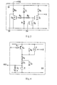
- FIG. 3 shows an embodiment of the inhibiting circuit Cl of figure 2 which is synthetically described, being already detailed with other embodiments in the Italian patent application No. 20173 A/83 in the name of the same Applicant.
- Unit CI comprises a threshold circuit consisting of a Zener diode ZI and of a resistance KI which is connected to a first and a second transistor Ql and Q2 via resistances R2 and R3.
- Transistor Q1 presents the gate electrode connected to the drain electrode of a further transistor Q3 which receives the said signal R over the gate electrode and further provides the drain electrode connected to a resistance R5.
- Transisiors Ql and Q3 form the said inhibiting electric branch whose activation occurs when transistor Q3 is cut off and when the output of the threshold circuit (anode of Z1) is active.
- Transistor Q2 provides the drain electrode connected to said supply voltage VDD via a resistance R4 and is conductive when the output of the threshold circuit (line open) is active, whereas it is cut off when the threshold circuit is deenergized (line closed).
- Signal S is extracted over the drain electrode of unit Q2 and provides therefore a level depending on the line condition.
- Figure 4 shows an embodiment of the supply unit UA of Figure 2 which is also described synthetically, being it better detailed in the aforesaid patent application.
- Unit UA mainly consists of a capacitor C which is located, via a diode DI and a resistance R6, by the telephone line via a resistance R8.
- unit C may be also loaded via a transistor Q4 whose base is connected to a resistance R7 and whose collector is connected to a resistance R6.
- Voltage VDD is available at the edges of unit C and is reduced by a Zener diode Z4 and possibly integrated by a cell P in series with a diode D2.
- a current generator G is activated by the same logic unit (output B), the said generator causing the extraction from the telephone line of an additional energy.
- Figure 5 illustrates in detail the unit adapted to identify the taxation impulses RI which results connected to the output of the bandpass filter via a resistance R9 and comprises a transistor Q5.
- a diode D3 is connected between the base of transistor Q5 and the other end of the output of the filter and is designed to render symetrical the charge seen from the filter.
- this latter sees the junction of Q5, while in the negative half-period it sees the junction of such diode D3.
- the collector of unit Q) results instead to be connected to said voltage VDD via a resistance R10.
- transistor Q5 When the output of the tilter provides an oscillation train of frequency F1, transistor Q5 becomes conductive in coincidence with the positive half-period of each oscillation.
- Unit Q5 renders therefore available a rectangular wave amplified signal of frequency Fl.
- Unit Q5 therefore represents an amplifier which requires energy from unit UA only in the instants when (in presence of signal Fl) becomes conductive and consequently its energy absorption is null in absence of taxation impulses.
- This rectangular wave signal is applied to the input of a frequency divider DV1 whose output renders available the said signal I which is designed to be tested by the logic unit UL which also generates signal rl for its resetting.
- Unit DV is designed to render available a signal of such a frequency as to be tested by a logic unit and is also arranged to provide a filtering element against disturbances possibly present at the edges of the resonant circuit.
- Figure 6 illustrates a preferred embodiment of logic unit UL which mainly consists of a unit uC of the low consumption type.
- unit UL is supplied with energy extracted from the telephone line, it is absolutely important minimizing the quantity of extracted energy in order not to increase relevantly the voltage fall occuring on the telephone line.
- unit uC provides an input H that on reception of a predetermined logic level sets unit uC into the low consumption condition. It is particularly possible setting unit uC in a condition in which the main functions result "frozen", thus obtaining a consumption of negligible extent.
- the logic unit according to the invention is so structured as to keep steadily unit uC in the low consumption condition as well as to determine the getting out of this condition only for a short time interval in response to a variation of input signals.
- Signal S is in fact applied to the input of unit uC via an impulse shaper F1 and via an exclusive logic sum EO; the output of this latter is connected to a further logic sum circuit OR.
- Unit EO allows to operate according to the aforesaid formality, since the second input receives a respective output of unit uC.
- unit uC In response to a level variation of signal S the activation of said signal H is detected and consequently unit uC gets out of the low consumption condition and performs the operations provided by the operative program. Alter having carried out these operations, unit uC changes the level of the signal present at the second input of unit EO returning into the low consumption condition until the next variation of signal S.
- unit OR receives the output 1 of said frequency divider DV1, a signal applicable through the activation of a pushbutton T1, as well as an output V of unit uC whose meaning will be specified later on.
- Unit uC is further connected to a random access memory of the nonvolatile type MM as well as a control circuit DD of display DS; such units receive from unit uC both data D and addresses A, as well as a selection control cs of the unit which data are destined to and possibly a writing control w.
- Unit uC is further associated with a keyboard TS and a further switch T2 which may be activated by a key.
- the random access memory MM are subdivided into a number of areas not smaller than the number K of the users of the telephone set.
- the memory of unit uC comprises K memory areas designed to receive the identification code numbers of the K subscribers and at least an area of work destined to sum the taxation impulses received during a telephone conversation.
- memory MM comprises K memory areas, each of them being designed to receive the number of impulses for a respective user and also comprises a further memory area adapted to receive the total number of impulses pertaining to the telephone line in question.
- the key is designed to be utilized by the owner of the terminal via the allotment to each memory area of a respective identification code number.
- This operation is actuated by way of pushbutton Tl in order to determine the getting out of ⁇ C from the low consumption condition and by activating switch T2 by way of this key in order to enabie ⁇ C to perform an operation of "code number allotment".
- the owner dials then the number of the memory area (e.g. area 7) and the code number (e.g. 7701) given to said area.
- the inhibiting circuit CI activates the said signal S and the engagement is detected by unit ⁇ C. This latter energizes its own output R and consequently when the subscriber starts a selection operation, there is detected the insertion of the said inhibiting electric branch comprised in unit Cl.
- unit ⁇ C causes the exclusion of the inhibiting branch, this exclusion being in any case controlled by unit ⁇ C when, on the ground of the test of signal S, detects an opening of long duration of the telephone line and consequently detects the end of the engagement.
- the comparison with positive result supplies unit ⁇ C with the indication of the subscriber who has performed the engagement and consequently this unit is adapted to send taxation impulses into the memory area (area 7) associated with that code number.
- unit CT generates taxation impulses, these are detected via the said circuit Kl by unit ⁇ C which stores them in the said area of work of its own internal memory.
- unit ⁇ C provides for summing the number of impulses stored in the area of work of its internal memory to the contents of area 7 of unit MM and to the contents of the area of the total number.
- the user dials then the indicative 7 of his memory area via keyboard IS and the contents of this area is monitored on display DS, via the said unit DD, for a time interval equal to the energization of output V of ⁇ C; thus, a reduction of energy consumption is detected.
- a possible reset of the memory areas of unit MM may be controlled by the owner , e.g. through a procedure such as: activation of pushbutton TI, activation of key T2 and activation of one or more keys of unit TS.
- unit ⁇ C may be connected to a number of mechanical counters (not shown) in the same number as that of the aforesaid memory areas. Alter detecting the code number of the subscriber who has engaged the telephone line unit ⁇ C sends the taxation impulses concerning the connection in progress towards the counter associated with the detected code number.
- each counter steadily supplies the information of the number of impulses pertaining to the relative user.
- Figure 7 shows a second embodiment of the logic unit UL (labeled UL1) adapted to cooperate with a further logic unit UL2 associated with the telephone set TL (see figure 8) in order to telecontrol the reading operations of the contents of memory MM from the telephone set itself.
- unit UL 1 comprises a microcomputer ⁇ C1 which is associated with said memory MM as well as with a frequency divider DV1 and with the said impulse shaper Fl, via units EO and OR 1.
- Keyboard TS, display DS, switches T1 and 12 are instead associated with a microcomputer ⁇ C provided in unit UL2.
- Unit ⁇ C2 may be formed by the same microcomputer provided for istance in keyboard telephone sets, so as unit TS may consist of the keyboard of the telephone set suitably enlarged.
- the exchange of information between units ⁇ C1 and ⁇ C2 is performed via a respective transceiving equipment connected to the telephone line.
- the transceiver associated with unit uCl comprises an oscillator OSI that, in response to the activation of an output of the microcomputer, generates an oscillation train of frequency F2 of a value for istance equal to 36KHz.
- unit OSI results to be connected (via a resistance R12) with an edge of a banpass filter PB2 provided by way of a ZOBEL cell, whose inductance is formed by the winding of a transformer.
- the same edge of unit PB2 results to be connected (via a resistance R13) on the ground of a transistor Q6 whose collector is connected to a supply source VDD (via a resistance R14).
- a diode D4 having the same function as diode D3 is connected between the base and the emitter of Q6.
- the collector of unit Q6 is connected to a frequency divider DV2, having the same function as the said unit DVI which results connected to the input of the same logic sum unit OR and reset by signal r2.
- the other edge of unit PB2 results connected to the telephone line.
- the transceiving equipment associated with unit ⁇ C2 comprises units corresponding to those specified now.
- a bandpass filter PB3 providing an edge connected between the hook MS of the microtelephone and circuits AT of the telephone set TL, while it provides the other edge connected to the output of an oscillator OSZ (via a resistance K15) as well as to the base of a transistor Q7 (via a resistance R16) whose collector is connected to a supply source VDD2 (via a resistance R17); a diode D5 having the same functions as the said diode D3 is connected between the base and the emitter of Q7.
- the collector of Q7 is further connected to a frequency divider DV3, whose output is applied to the input of unit ⁇ C2 via a logic sum unit OR2 whose output is connected to the said input H of microcomputer ⁇ C2.
- the exchange of information, between unit ⁇ C2 and unit ⁇ C1 occurs according to formalities comparable with a binary configuration, since a fixed number of oscillation groups of frequency F2 (e.g. 8 groups) is everytime transmitted, where each group presents a long or short duration with relation to the logic level (one or zero) of the binary information to be transmitted.
- a fixed number of oscillation groups of frequency F2 e.g. 8 groups
- the binary configuration (e.g. of 8 bits) may be transmitted through the emission of a predetermined number of duration modulated oscillation groups.
- the user wishes to monitor the contents of a generical memory area, he operates pushbutton T1 (see figure 8) as well as the key of unit TS corresponding to such an area.
- Unit ⁇ C2 detects such events and codes them according to the aforesaid formalities, thus determining the emission by OS2 of a predetermined number of oscillation groups modulated as stated above. Such groups are detected by unit ⁇ C1 via unit PB3, the telephone line and units PB2, Q6 and DV2.
- Unit ⁇ C1 detects the duration of the single oscillation groups and rebuilds the binary configuration indicating the control generated by ⁇ C2 following to the operation performed by the user.
- unit ⁇ C1 Upon interpretation of the request, unit ⁇ C1 extracts from the respective area of unit MM a binary configuration indicating the number of taxation impulses totalized therein and transfers such a configuration into unit ⁇ C2 translating it as stated above into a plurality of activations of unit OS1.
- the oscillation groups generated by OSI are applied to ⁇ C2 via units PB2, telephone line, PB3, Q7 and DV3.
- Unit ⁇ C2 therefore determines the monitoring of the information received on display DS via the relative control circuit DD.
Landscapes
- Engineering & Computer Science (AREA)
- Computer Security & Cryptography (AREA)
- Signal Processing (AREA)
- Computer Networks & Wireless Communication (AREA)
- Meter Arrangements (AREA)
- Telephone Function (AREA)
Applications Claiming Priority (2)
| Application Number | Priority Date | Filing Date | Title |
|---|---|---|---|
| IT8320174A IT1212715B (it) | 1983-03-21 | 1983-03-21 | Disposizione circuitale per il conteggio e la ripartizione degli impulsi di tassazione che competono ad una generica linea telefonica. |
| IT2017483 | 1983-03-21 |
Publications (2)
| Publication Number | Publication Date |
|---|---|
| EP0123330A2 true EP0123330A2 (de) | 1984-10-31 |
| EP0123330A3 EP0123330A3 (de) | 1986-02-05 |
Family
ID=11164416
Family Applications (1)
| Application Number | Title | Priority Date | Filing Date |
|---|---|---|---|
| EP84200345A Withdrawn EP0123330A3 (de) | 1983-03-21 | 1984-03-12 | Schaltungsanordnung zur Zählung und Verteilung von Gebührenimpulsen eines gemeinsam benutzten Fernsprechanschlusses |
Country Status (4)
| Country | Link |
|---|---|
| EP (1) | EP0123330A3 (de) |
| DE (1) | DE123330T1 (de) |
| ES (1) | ES530737A0 (de) |
| IT (1) | IT1212715B (de) |
Cited By (2)
| Publication number | Priority date | Publication date | Assignee | Title |
|---|---|---|---|---|
| AT397447B (de) * | 1986-11-06 | 1994-04-25 | Schrack Elektronik Ag | Digitale nebenstellenanlage mit fernsprechgebührenübertragung |
| CN1064802C (zh) * | 1994-05-18 | 2001-04-18 | 西门子公司 | 限制计费脉冲电平的电路装置 |
-
1983
- 1983-03-21 IT IT8320174A patent/IT1212715B/it active
-
1984
- 1984-03-12 EP EP84200345A patent/EP0123330A3/de not_active Withdrawn
- 1984-03-12 DE DE198484200345T patent/DE123330T1/de active Pending
- 1984-03-16 ES ES530737A patent/ES530737A0/es active Granted
Non-Patent Citations (2)
| Title |
|---|
| INSTITUTE OF ELECTRICAL AND ELECTRONICS ENGINEERS. INTERNATIONAL CONFERENCE ON COMMUNICATIONS, Boulder, Colorado, 9th-11th June 1969, Edited by R.K.Saleman, pages 43-9 - 43-14, New York, US; J.S.SOMERVILLE: "A new central office facility for extension number billing of PBX originated toll calls" * |
| TELEFON REPORT SIEMENS, vol. 13, no. 2, 1977, pages 61-64, M}nchen, DE; H.H]TTL: "Geb}hren-Processor 1001 - Geb}hrenerfassung in Fernsprech-Nebenstellenanlagen" * |
Cited By (2)
| Publication number | Priority date | Publication date | Assignee | Title |
|---|---|---|---|---|
| AT397447B (de) * | 1986-11-06 | 1994-04-25 | Schrack Elektronik Ag | Digitale nebenstellenanlage mit fernsprechgebührenübertragung |
| CN1064802C (zh) * | 1994-05-18 | 2001-04-18 | 西门子公司 | 限制计费脉冲电平的电路装置 |
Also Published As
| Publication number | Publication date |
|---|---|
| IT8320174A0 (it) | 1983-03-21 |
| ES8502828A1 (es) | 1985-02-01 |
| DE123330T1 (de) | 1985-03-07 |
| EP0123330A3 (de) | 1986-02-05 |
| ES530737A0 (es) | 1985-02-01 |
| IT1212715B (it) | 1989-11-30 |
Similar Documents
| Publication | Publication Date | Title |
|---|---|---|
| CA1297565C (en) | Call screening in a public telephone station | |
| US4126762A (en) | Method and system for accumulating data over nondedicated telephone lines | |
| US4006316A (en) | Code-controlled detection and function actuating system | |
| US4099033A (en) | Telephone security device | |
| US4675899A (en) | Frequency ring director | |
| US4866762A (en) | Apparatus for restricting telephone calls | |
| KR840003172A (ko) | 코드레스 텔레폰을 위한 전화 보안 시스템 | |
| US4425480A (en) | Telephone station apparatus with selective restricting of local calls | |
| US4358640A (en) | Telephone security device | |
| US4683583A (en) | Method and apparatus for controlling telephone line access | |
| US4782516A (en) | Fraud prevention in a public telephone station | |
| US2281508A (en) | Telephone system | |
| US3757055A (en) | Electronic toll restrictor | |
| US2892037A (en) | Electrical information system | |
| US2694801A (en) | Pulse counting and registration system | |
| US4161721A (en) | Alarm device having code verification system | |
| EP0123330A2 (de) | Schaltungsanordnung zur Zählung und Verteilung von Gebührenimpulsen eines gemeinsam benutzten Fernsprechanschlusses | |
| US3996425A (en) | Call denial circuit | |
| EP0126496A2 (de) | Sperrvorrichtung für Fernsprechteilnehmeranschluss | |
| US4085293A (en) | Traffic usage recorder | |
| US3749847A (en) | Device for blocking toll calls from subscriber telephones | |
| US4000380A (en) | Toll restrictor for touch type digit selector | |
| US3798381A (en) | Inhibiting trunk calls from private branch exchanges | |
| US3804984A (en) | Emergency circuitry for coin telephone | |
| US3702902A (en) | Telephone dialing equipment |
Legal Events
| Date | Code | Title | Description |
|---|---|---|---|
| PUAI | Public reference made under article 153(3) epc to a published international application that has entered the european phase |
Free format text: ORIGINAL CODE: 0009012 |
|
| AK | Designated contracting states |
Designated state(s): AT BE CH DE FR GB LI LU NL SE |
|
| TCAT | At: translation of patent claims filed | ||
| EL | Fr: translation of claims filed | ||
| TCNL | Nl: translation of patent claims filed | ||
| DET | De: translation of patent claims | ||
| REG | Reference to a national code |
Ref country code: DE Ref legal event code: 8580 Free format text: ES ERFOLGT EIN NEUDRUCK MIT DEN RICHTIGEN PATENTANSPRUECHEN. |
|
| PUAL | Search report despatched |
Free format text: ORIGINAL CODE: 0009013 |
|
| AK | Designated contracting states |
Designated state(s): AT BE CH DE FR GB LI LU NL SE |
|
| STAA | Information on the status of an ep patent application or granted ep patent |
Free format text: STATUS: THE APPLICATION IS DEEMED TO BE WITHDRAWN |
|
| 18D | Application deemed to be withdrawn |
Effective date: 19861001 |
|
| RIN1 | Information on inventor provided before grant (corrected) |
Inventor name: BESI, MARIO Inventor name: PANFILI, GABRIELE |