EP0123600A1 - Rohrverbindung mit einer Ringverankerung an einem Ende - Google Patents
Rohrverbindung mit einer Ringverankerung an einem Ende Download PDFInfo
- Publication number
- EP0123600A1 EP0123600A1 EP84400702A EP84400702A EP0123600A1 EP 0123600 A1 EP0123600 A1 EP 0123600A1 EP 84400702 A EP84400702 A EP 84400702A EP 84400702 A EP84400702 A EP 84400702A EP 0123600 A1 EP0123600 A1 EP 0123600A1
- Authority
- EP
- European Patent Office
- Prior art keywords
- ring
- tube
- groove
- mandrel
- deformation
- Prior art date
- Legal status (The legal status is an assumption and is not a legal conclusion. Google has not performed a legal analysis and makes no representation as to the accuracy of the status listed.)
- Granted
Links
- 238000000034 method Methods 0.000 claims abstract description 16
- 238000003825 pressing Methods 0.000 claims abstract description 3
- 238000004873 anchoring Methods 0.000 claims description 11
- 238000002788 crimping Methods 0.000 claims description 5
- 238000007789 sealing Methods 0.000 claims description 2
- 230000003313 weakening effect Effects 0.000 description 2
- 235000008612 Gnetum gnemon Nutrition 0.000 description 1
- 240000000018 Gnetum gnemon Species 0.000 description 1
- 230000006835 compression Effects 0.000 description 1
- 238000007906 compression Methods 0.000 description 1
- 230000007423 decrease Effects 0.000 description 1
- 230000000694 effects Effects 0.000 description 1
- 239000000446 fuel Substances 0.000 description 1
- 239000000463 material Substances 0.000 description 1
- 230000002787 reinforcement Effects 0.000 description 1
- 238000000926 separation method Methods 0.000 description 1
- 239000007787 solid Substances 0.000 description 1
Images


Classifications
-
- F—MECHANICAL ENGINEERING; LIGHTING; HEATING; WEAPONS; BLASTING
- F16—ENGINEERING ELEMENTS AND UNITS; GENERAL MEASURES FOR PRODUCING AND MAINTAINING EFFECTIVE FUNCTIONING OF MACHINES OR INSTALLATIONS; THERMAL INSULATION IN GENERAL
- F16L—PIPES; JOINTS OR FITTINGS FOR PIPES; SUPPORTS FOR PIPES, CABLES OR PROTECTIVE TUBING; MEANS FOR THERMAL INSULATION IN GENERAL
- F16L13/00—Non-disconnectable pipe joints, e.g. soldered, adhesive, or caulked joints
- F16L13/14—Non-disconnectable pipe joints, e.g. soldered, adhesive, or caulked joints made by plastically deforming the material of the pipe, e.g. by flanging, rolling
- F16L13/141—Non-disconnectable pipe joints, e.g. soldered, adhesive, or caulked joints made by plastically deforming the material of the pipe, e.g. by flanging, rolling by crimping or rolling from the outside
-
- B—PERFORMING OPERATIONS; TRANSPORTING
- B21—MECHANICAL METAL-WORKING WITHOUT ESSENTIALLY REMOVING MATERIAL; PUNCHING METAL
- B21D—WORKING OR PROCESSING OF SHEET METAL OR METAL TUBES, RODS OR PROFILES WITHOUT ESSENTIALLY REMOVING MATERIAL; PUNCHING METAL
- B21D39/00—Application of procedures in order to connect objects or parts, e.g. coating with sheet metal otherwise than by plating; Tube expanders
- B21D39/04—Application of procedures in order to connect objects or parts, e.g. coating with sheet metal otherwise than by plating; Tube expanders of tubes with tubes; of tubes with rods
-
- F—MECHANICAL ENGINEERING; LIGHTING; HEATING; WEAPONS; BLASTING
- F16—ENGINEERING ELEMENTS AND UNITS; GENERAL MEASURES FOR PRODUCING AND MAINTAINING EFFECTIVE FUNCTIONING OF MACHINES OR INSTALLATIONS; THERMAL INSULATION IN GENERAL
- F16L—PIPES; JOINTS OR FITTINGS FOR PIPES; SUPPORTS FOR PIPES, CABLES OR PROTECTIVE TUBING; MEANS FOR THERMAL INSULATION IN GENERAL
- F16L13/00—Non-disconnectable pipe joints, e.g. soldered, adhesive, or caulked joints
- F16L13/14—Non-disconnectable pipe joints, e.g. soldered, adhesive, or caulked joints made by plastically deforming the material of the pipe, e.g. by flanging, rolling
- F16L13/147—Non-disconnectable pipe joints, e.g. soldered, adhesive, or caulked joints made by plastically deforming the material of the pipe, e.g. by flanging, rolling by radially expanding the inner part
-
- F—MECHANICAL ENGINEERING; LIGHTING; HEATING; WEAPONS; BLASTING
- F16—ENGINEERING ELEMENTS AND UNITS; GENERAL MEASURES FOR PRODUCING AND MAINTAINING EFFECTIVE FUNCTIONING OF MACHINES OR INSTALLATIONS; THERMAL INSULATION IN GENERAL
- F16L—PIPES; JOINTS OR FITTINGS FOR PIPES; SUPPORTS FOR PIPES, CABLES OR PROTECTIVE TUBING; MEANS FOR THERMAL INSULATION IN GENERAL
- F16L19/00—Joints in which sealing surfaces are pressed together by means of a member, e.g. a swivel nut, screwed on, or into, one of the joint parts
- F16L19/02—Pipe ends provided with collars or flanges, integral with the pipe or not, pressed together by a screwed member
- F16L19/025—Pipe ends provided with collars or flanges, integral with the pipe or not, pressed together by a screwed member the pipe ends having integral collars or flanges
- F16L19/028—Pipe ends provided with collars or flanges, integral with the pipe or not, pressed together by a screwed member the pipe ends having integral collars or flanges the collars or flanges being obtained by deformation of the pipe wall
-
- Y—GENERAL TAGGING OF NEW TECHNOLOGICAL DEVELOPMENTS; GENERAL TAGGING OF CROSS-SECTIONAL TECHNOLOGIES SPANNING OVER SEVERAL SECTIONS OF THE IPC; TECHNICAL SUBJECTS COVERED BY FORMER USPC CROSS-REFERENCE ART COLLECTIONS [XRACs] AND DIGESTS
- Y10—TECHNICAL SUBJECTS COVERED BY FORMER USPC
- Y10T—TECHNICAL SUBJECTS COVERED BY FORMER US CLASSIFICATION
- Y10T29/00—Metal working
- Y10T29/49—Method of mechanical manufacture
- Y10T29/49826—Assembling or joining
- Y10T29/49908—Joining by deforming
- Y10T29/49915—Overedge assembling of seated part
- Y10T29/4992—Overedge assembling of seated part by flaring inserted cup or tube end
-
- Y—GENERAL TAGGING OF NEW TECHNOLOGICAL DEVELOPMENTS; GENERAL TAGGING OF CROSS-SECTIONAL TECHNOLOGIES SPANNING OVER SEVERAL SECTIONS OF THE IPC; TECHNICAL SUBJECTS COVERED BY FORMER USPC CROSS-REFERENCE ART COLLECTIONS [XRACs] AND DIGESTS
- Y10—TECHNICAL SUBJECTS COVERED BY FORMER USPC
- Y10T—TECHNICAL SUBJECTS COVERED BY FORMER US CLASSIFICATION
- Y10T29/00—Metal working
- Y10T29/49—Method of mechanical manufacture
- Y10T29/49826—Assembling or joining
- Y10T29/49908—Joining by deforming
- Y10T29/49938—Radially expanding part in cavity, aperture, or hollow body
- Y10T29/4994—Radially expanding internal tube
-
- Y—GENERAL TAGGING OF NEW TECHNOLOGICAL DEVELOPMENTS; GENERAL TAGGING OF CROSS-SECTIONAL TECHNOLOGIES SPANNING OVER SEVERAL SECTIONS OF THE IPC; TECHNICAL SUBJECTS COVERED BY FORMER USPC CROSS-REFERENCE ART COLLECTIONS [XRACs] AND DIGESTS
- Y10—TECHNICAL SUBJECTS COVERED BY FORMER USPC
- Y10T—TECHNICAL SUBJECTS COVERED BY FORMER US CLASSIFICATION
- Y10T29/00—Metal working
- Y10T29/53—Means to assemble or disassemble
- Y10T29/5367—Coupling to conduit
Definitions
- the invention relates to tube connections. It relates in particular to the connections of small diameter and / or thin-walled tubes, such as those used for the distribution of fuel in aircraft or automobile engines.
- an axially compressible mandrel is introduced into the tube, then using a suitable system, its circumference is extended at the level of the grooves of the ring, and the wall of the tube is thus radially stamped. direction of the bottom of the said gorges. Then after having carried out this deformation of the tube from the inside, the compression force is eliminated and the mandrel is removed.
- the tube remains anchored in its ring, and can then be connected in the usual way using a connector body and a nut screwing onto it.
- the most frequently used rings are relatively long and, to ensure sufficient anchoring, comprise two successive grooves defining a separation rib and an end rib.
- the deformation of the tube being limited, the presence in the ring of several ribs is necessary to ensure proper attachment.
- the compressible mandrel is fragile and ruptures in the case of a small diameter of the tube, and the process becomes more and more difficult to apply as the thickness of the wall of the tube decreases.
- the tube is stretched radially and longitudinally, and therefore the thickness of its wall slightly reduced, which is noticeable in a tube with very wall slim.
- the presence of ribs causes bends in the tube with the beginning of the weakening line, which are aggravated when the ring is clamped in the fitting body and the tightening nut.
- the traditional external thickness of a ring corresponds to, element with the most central groove, and a thin zone corresponds to the end groove, and this zone is fragile.
- an anchoring method of the type consisting in deforming a tube inside an inner grooved ring, characterized in that the deformation of the tube is obtained by pressing on the end section of its wall, a solid rigid mandrel with smooth wall being temporarily placed inside the tube (and preventing any deformation inwards), the pressure exerted longitudinally at the end of said tube causing the deformation by discharge of the wall of this tube at the level of the groove of the ring in such a way that it ensures an inseparable fixing between the ring and the tube.
- the tube (possibly with its ring) is held externally by one or more sleeves and / or shells, and internally by the mandrel of appropriate diameter, so that the only area d expansion is determined by the groove of the ring.
- the introduction of the mandrel into the tube and the pressure on the end section of this tube are carried out simultaneously at the end of the stroke of the mandrel.
- the mandrel has a suitable shoulder for abutting, then exerting pressure on the end section of the tube.
- the tube slightly protrudes from the ring and the mandrel has two successive shoulders, so that when it is introduced into the tube, the first shoulder causes the tube to flare and the second exerts pressure on the end section of this same tube.
- two mandrels are used successively.
- the first mandrel has a single shoulder which is applied to the end section of the tube and is used only to exert the pressure necessary for deformation at the level of the groove or grooves of the ring. During this operation, the part of the tube projecting beyond the ring is held in place by an appropriate sleeve.
- a second mandrel comprising a single shoulder and a wider part is introduced into the tube to flare the part protruding from the ring and to apply the deformation formed on the nose of said ring.
- the invention relates not only to the method, but also to the connection device.
- the ring used has a cylindrical conduit without rib or other internal roughness, but with a wide groove located at an external allowance, preferably provided substantially in the middle.
- the ring has, inside the first groove, a second groove.
- This second groove has a smaller width, but a diameter greater than the first groove.
- This second groove can be provided anywhere in the bottom of the first groove, for example, either along an edge of the first groove, or in the center of this first groove in such a way that a circular area of the said first groove remains on either side of the second groove, thus determining the anchoring and sealing shoulders required.
- the wall of the tube in a ring with a groove, has two circular attachment zones corresponding to the two shoulders determined by the groove inside the ring.
- the wall of the tube in the case of crimping in a concentric grooved gauge, has three or four circular attachment zones corresponding to the two, or three shoulders determined by the two circular grooves inside the ring (depending on whether the second groove is located at one end or not of the first groove).
- the flared part of the tube exceeds the ring and the deformation zone (connecting the flared portion to the non-flared portion) is in the pliquée on the nose of the said ring, which constitutes a further shoulder, and thus a circular area additional attachment.
- the mandrel and the sleeves are removed and the tube crimped in its ring can then be connected using a connector body and the nut screwing on him.
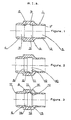
- Fig. 1 shows in section a ring 1 having externally a tube 2 with a mouth 2 ', in the center a reinforcement 3 and, at the other end, a tube 4 without internal mouth, but with an external slope (preferably a spherical sector) .
- the ring 1 comprises a duct 5, a groove 6 and a duct 7.
- the ducts 5 and 7 are of the same diameter and with a smooth wall.
- the groove 6 is of a substantially larger diameter with a smooth cylindrical wall.
- the groove 6 has shoulders 8 and 9 in opposite directions.
- Fig. 2 represents a ring identical to FIG. 1 but with a second groove 10, concentric with the first 6, and comprising a shoulder 11 (in the same direction as the shoulder 8) and a shoulder 12 replacing the shoulder 9 and more pronounced.
- Fig. 3 represents a ring identical to FIG. 1, but with a groove 13 concentric with the groove 6, at its center, so as to determine areas 14 and 15 as well as shoulders 11 and 16.
- this ring has the shoulders 8 and 11 in one direction, and 16 and 12 in the other direction.
- it is necessary to add the nose 17 of the ring which also plays the role of shoulder when the tube is flared.
- the crimping process is illustrated in Figs. 4 to 9.
- the ring 1 is threaded on the tube 18 so that it exceeds it.
- a sleeve 19 is applied to the tube to hold it in place, and possibly shells 30 can be provided to support the ring 1.
- the sleeves and shells prevent deformations of the tube in undesired places.
- the mandrel 20 is full and consists of three cylindrical parts of increasing diameters 21, 23, 25 determining between them shoulders 22 and 24. When the mandrel 20 is introduced inside the tube 18, the part 21 s' normally pushes down to the shoulder 22 slightly inclined so that the part 23 in turn penetrates inside the tube 18 flaring it at 26 until its periphery 27 abuts against the shoulder 24.
- the shoulder 24 exerts a very high pressure on the end section 27 of the tube 18, the wall of which is pushed back inside the ring 1.
- the tube 18 which is blocked in the sleeve 19 tends to deform only at the level of the ring 1 and enters its grooves 6 and 13.
- the wall 18 is supported on the various internal shoulders.
- the material, of which the tube is made up is packed and the wall tends to thicken instead of thinning as in the expansion, and also to harden, giving the end of the tube thus treated a higher robustness.
- the deformation 26 of the flared part of the tube 18 is applied to the nose 17 of the ring 1. After removal of the mandrel 20, the tube 18 remains crimped in the ring and has five anchoring points in relation to the shoulders 8 , 11, 16, 12 17. Finally the sleeve 19 is also removed.
- the tube 18 provided with its ring 1 is placed in the connector body 28 on which the nut 29 is screwed.
- the flared part of the tube 18 then protrudes from the ring 1 by a distance such that its end part comes into contact with the connection cone 28 so as to produce a direct mechanical connection between the tube 18 and the connection body 28, and possibly an additional seal.
- the present invention also applies to other tubes.
- the mandrels can be designed for tubes having any cross-section.
Landscapes
- Engineering & Computer Science (AREA)
- General Engineering & Computer Science (AREA)
- Mechanical Engineering (AREA)
- Mutual Connection Of Rods And Tubes (AREA)
- Joints With Pressure Members (AREA)
- Lining Or Joining Of Plastics Or The Like (AREA)
- Non-Disconnectible Joints And Screw-Threaded Joints (AREA)
- Forging (AREA)
Applications Claiming Priority (2)
| Application Number | Priority Date | Filing Date | Title |
|---|---|---|---|
| FR8305872 | 1983-04-11 | ||
| FR8305872A FR2543857B1 (fr) | 1983-04-11 | 1983-04-11 | Raccordement de tube comportant l'ancrage d'une bague sur son extremite |
Publications (2)
| Publication Number | Publication Date |
|---|---|
| EP0123600A1 true EP0123600A1 (de) | 1984-10-31 |
| EP0123600B1 EP0123600B1 (de) | 1988-06-22 |
Family
ID=9287708
Family Applications (1)
| Application Number | Title | Priority Date | Filing Date |
|---|---|---|---|
| EP84400702A Expired EP0123600B1 (de) | 1983-04-11 | 1984-04-10 | Rohrverbindung mit einer Ringverankerung an einem Ende |
Country Status (13)
| Country | Link |
|---|---|
| US (2) | US4688318A (de) |
| EP (1) | EP0123600B1 (de) |
| JP (1) | JPS59205094A (de) |
| AU (2) | AU2663484A (de) |
| BR (1) | BR8401669A (de) |
| DE (1) | DE3472225D1 (de) |
| EG (1) | EG16430A (de) |
| ES (1) | ES8505561A1 (de) |
| FR (1) | FR2543857B1 (de) |
| IL (1) | IL71489A0 (de) |
| IN (1) | IN160638B (de) |
| RO (1) | RO92497B (de) |
| YU (1) | YU65584A (de) |
Families Citing this family (20)
| Publication number | Priority date | Publication date | Assignee | Title |
|---|---|---|---|---|
| US4844517A (en) * | 1987-06-02 | 1989-07-04 | Sierracin Corporation | Tube coupling |
| US4835536A (en) * | 1987-12-21 | 1989-05-30 | Honeywell Inc. | Weather radar with turbulence detection |
| FR2642500B1 (fr) * | 1989-01-30 | 1991-04-19 | Parker Hannifin Rak Sa | Procede de realisation d'un raccord etanche pour tube rigide et raccord en resultant |
| US5058936A (en) * | 1989-02-23 | 1991-10-22 | Raychem Corporation | Method of forming a mechanical |
| DE4002494A1 (de) * | 1990-01-29 | 1991-08-08 | Airbus Gmbh | Rohrverschraubung |
| US5447391A (en) * | 1993-09-30 | 1995-09-05 | Shell Oil Company | Offshore platform structure and system |
| US5445476A (en) * | 1993-09-30 | 1995-08-29 | Shell Oil Company | Reusable offshore platform jacket |
| US5593250A (en) * | 1994-12-23 | 1997-01-14 | Shell Offshore Inc. | Hyjack platform with buoyant rig supplemental support |
| US5741089A (en) * | 1994-12-23 | 1998-04-21 | Shell Offshore Inc. | Method for enhanced redeployability of hyjack platforms |
| US5551801A (en) * | 1994-12-23 | 1996-09-03 | Shell Offshore Inc. | Hyjack platform with compensated dynamic response |
| US5607194A (en) * | 1995-04-20 | 1997-03-04 | Universal Enterprises, Inc. | Member and tube assembly |
| US6517126B1 (en) * | 2000-09-22 | 2003-02-11 | General Electric Company | Internal swage fitting |
| JP4992098B2 (ja) * | 2007-06-05 | 2012-08-08 | 株式会社水研 | ノンボルト継手構造およびノンボルト継手構造を形成する方法 |
| GB2462814B (en) * | 2008-08-19 | 2010-10-06 | Rolls Royce Plc | Method of manufacturing thin wall isogrid casings |
| EP2184525B1 (de) * | 2008-11-06 | 2011-10-19 | Eifeler Maschinenbau GmbH | Rohrverbindung mit einem Rohr und Verfahren zur Herstellung eines Verbindungsabschnitts einer Rohrverbindung |
| US9772056B2 (en) | 2009-03-05 | 2017-09-26 | Gates Corporation | Tube connector |
| US9091376B2 (en) * | 2010-12-30 | 2015-07-28 | Eaton Corporation | Method of forming an internal tube beadlock |
| US9982813B2 (en) * | 2015-03-27 | 2018-05-29 | Designed Metal Connections, Inc. | Swage fitting |
| CN112935817B (zh) * | 2021-03-12 | 2022-11-15 | 四川明日宇航工业有限责任公司 | 一种航空环形件加工方法 |
| DE102022121718A1 (de) * | 2022-08-26 | 2024-02-29 | Johannes Schäfer vorm. Stettiner Schraubenwerke GmbH & Co. KG | Verbindung eines rohrförmigen Bauteils mit einem Anschlussteil |
Citations (10)
| Publication number | Priority date | Publication date | Assignee | Title |
|---|---|---|---|---|
| DE192072C (de) * | ||||
| FR1536521A (fr) * | 1900-01-01 | Genevac Ltd | élément de raccord | |
| DE540825C (de) * | 1929-05-09 | 1932-01-07 | Ver Stahlwerke Akt Ges | Verfahren zur Ausbildung des Muffenendes bzw. des Spitzendes von zur Herstellung vonSicherheitsschweissmuffenverbindungen dienenden Rohren |
| FR1064906A (fr) * | 1952-10-22 | 1954-05-19 | British Oxygen Co Ltd | Joint de tubes métalliques dans une pièce métallique |
| US2857666A (en) * | 1950-12-11 | 1958-10-28 | Walter O Beyer | Making coupling assemblies |
| US3467414A (en) * | 1966-09-30 | 1969-09-16 | Ronald T Downing | Tube joint having buckled locking means |
| US3730567A (en) * | 1970-07-08 | 1973-05-01 | Axial Corp | Coupling sleeve |
| FR2171718A5 (de) * | 1972-02-02 | 1973-09-21 | Btr Industries Ltd | |
| US4130932A (en) * | 1975-11-11 | 1978-12-26 | Arkla Industries, Inc. | Method of joining a tube to a plate |
| GB2024973A (en) * | 1978-06-19 | 1980-01-16 | Ridenour Ralph | Tube Fitting Assembly With Deformable Seal |
Family Cites Families (17)
| Publication number | Priority date | Publication date | Assignee | Title |
|---|---|---|---|---|
| US2477676A (en) * | 1949-08-02 | Tubnable coupling member | ||
| US2685461A (en) * | 1949-09-22 | 1954-08-03 | Mueller Co | Pipe coupling |
| DE1022061B (de) * | 1955-03-19 | 1958-01-02 | Ver Kesselwerke Ag | Verbindung zwischen einem austenitischen und einem ferritischen Rohr |
| US3188733A (en) * | 1961-07-28 | 1965-06-15 | Mcdowell Mfg Co | Torque joint |
| FR81781E (fr) * | 1962-06-14 | 1963-11-08 | Commissariat Energie Atomique | Procédé et appareil de fixation étanche d'un tube sur un fourreau ou analogue |
| BE683803A (de) * | 1966-07-07 | 1966-12-16 | ||
| US3484123A (en) * | 1968-04-18 | 1969-12-16 | Boeing Co | Reuseable flareless tube coupling |
| US3711132A (en) * | 1970-06-17 | 1973-01-16 | Resistoflex Corp | Metal tube end fitting |
| US3778090A (en) * | 1972-05-18 | 1973-12-11 | Gen Motors Corp | Beaded tube with o-ring seal connection |
| SE7505866L (sv) * | 1974-06-06 | 1975-12-08 | Boeing Co | Kopplingshylsa |
| GB1472458A (en) * | 1974-06-21 | 1977-05-04 | Shell Int Research | Apparatus and a method for treating a surface in particular for spraying an insulating foam on a wall |
| US3967840A (en) * | 1975-03-13 | 1976-07-06 | Caterpillar Tractor Co. | Joint and process for forming same |
| US4043160A (en) * | 1975-12-18 | 1977-08-23 | The Boeing Company | Internal tooling for swaging apparatus |
| FR2412778A1 (fr) * | 1977-12-20 | 1979-07-20 | Eljika | Dispositif de jonction et de raccordement de tuyaux flexibles et procede de montage d'un tel dispositif |
| JPS5545979U (de) * | 1978-09-22 | 1980-03-26 | ||
| FR2437560A1 (fr) * | 1978-09-26 | 1980-04-25 | Legris France Sa | Perfectionnement aux raccords pour tuyauteries notamment pour tuyauteries de fluides a haute pression |
| FR2488354A1 (fr) * | 1980-08-06 | 1982-02-12 | Nadella | Dispositif de transmission comportant un joint de cardan ou autre organe d'accouplement |
-
1983
- 1983-04-11 FR FR8305872A patent/FR2543857B1/fr not_active Expired
-
1984
- 1984-04-06 US US06/597,255 patent/US4688318A/en not_active Expired - Fee Related
- 1984-04-08 EG EG229/84A patent/EG16430A/xx active
- 1984-04-09 RO RO114210A patent/RO92497B/ro unknown
- 1984-04-09 AU AU26634/84A patent/AU2663484A/en not_active Abandoned
- 1984-04-10 EP EP84400702A patent/EP0123600B1/de not_active Expired
- 1984-04-10 IL IL71489A patent/IL71489A0/xx unknown
- 1984-04-10 DE DE8484400702T patent/DE3472225D1/de not_active Expired
- 1984-04-10 BR BR8401669A patent/BR8401669A/pt unknown
- 1984-04-10 YU YU00655/84A patent/YU65584A/xx unknown
- 1984-04-11 JP JP59072589A patent/JPS59205094A/ja active Pending
- 1984-04-11 ES ES531535A patent/ES8505561A1/es not_active Expired
- 1984-04-17 IN IN269/MAS/84A patent/IN160638B/en unknown
-
1987
- 1987-01-15 US US07/006,306 patent/US4805945A/en not_active Expired - Fee Related
-
1988
- 1988-01-06 AU AU10098/88A patent/AU1009888A/en not_active Abandoned
Patent Citations (10)
| Publication number | Priority date | Publication date | Assignee | Title |
|---|---|---|---|---|
| DE192072C (de) * | ||||
| FR1536521A (fr) * | 1900-01-01 | Genevac Ltd | élément de raccord | |
| DE540825C (de) * | 1929-05-09 | 1932-01-07 | Ver Stahlwerke Akt Ges | Verfahren zur Ausbildung des Muffenendes bzw. des Spitzendes von zur Herstellung vonSicherheitsschweissmuffenverbindungen dienenden Rohren |
| US2857666A (en) * | 1950-12-11 | 1958-10-28 | Walter O Beyer | Making coupling assemblies |
| FR1064906A (fr) * | 1952-10-22 | 1954-05-19 | British Oxygen Co Ltd | Joint de tubes métalliques dans une pièce métallique |
| US3467414A (en) * | 1966-09-30 | 1969-09-16 | Ronald T Downing | Tube joint having buckled locking means |
| US3730567A (en) * | 1970-07-08 | 1973-05-01 | Axial Corp | Coupling sleeve |
| FR2171718A5 (de) * | 1972-02-02 | 1973-09-21 | Btr Industries Ltd | |
| US4130932A (en) * | 1975-11-11 | 1978-12-26 | Arkla Industries, Inc. | Method of joining a tube to a plate |
| GB2024973A (en) * | 1978-06-19 | 1980-01-16 | Ridenour Ralph | Tube Fitting Assembly With Deformable Seal |
Also Published As
| Publication number | Publication date |
|---|---|
| IN160638B (de) | 1987-07-25 |
| AU1009888A (en) | 1988-04-21 |
| YU65584A (en) | 1989-02-28 |
| DE3472225D1 (en) | 1988-07-28 |
| BR8401669A (pt) | 1984-11-20 |
| EP0123600B1 (de) | 1988-06-22 |
| US4688318A (en) | 1987-08-25 |
| EG16430A (en) | 1987-04-30 |
| FR2543857A1 (fr) | 1984-10-12 |
| US4805945A (en) | 1989-02-21 |
| IL71489A0 (en) | 1984-07-31 |
| ES531535A0 (es) | 1985-06-01 |
| ES8505561A1 (es) | 1985-06-01 |
| RO92497B (ro) | 1988-07-01 |
| RO92497A (ro) | 1988-06-30 |
| FR2543857B1 (fr) | 1986-05-09 |
| JPS59205094A (ja) | 1984-11-20 |
| AU2663484A (en) | 1984-10-18 |
Similar Documents
| Publication | Publication Date | Title |
|---|---|---|
| EP0123600A1 (de) | Rohrverbindung mit einer Ringverankerung an einem Ende | |
| EP1144900B1 (de) | Vorrichtung zum schnellverbinden eines rohres an einem starren element | |
| FR2705432A1 (fr) | Système de liaison par douilles coulissantes, pour tubes cylindriques en matière plastique. | |
| EP0151889A1 (de) | Rohrverbindung und Verfahren zum Zusammenbau | |
| FR2847646A1 (fr) | Raccord de tuyau | |
| FR2818338A1 (fr) | Soufflet d'etancheite, joint de transmission d'un tel soufflet et procede de fixation d'un tel soufflet | |
| EP1319147B1 (de) | Anschlussverbindung zwischen einem rohrförmigen element und einem rohr | |
| FR2583928A1 (fr) | Dispositif pour la connexion tenant la pression du conducteur exterieur d'un cable coaxial | |
| FR2740531A1 (fr) | Perfectionnement a un dispositif de liaison d'un tube a un embout | |
| FR2789610A1 (fr) | Procede de fabrication d'une rampe commune | |
| WO2016001550A1 (fr) | Connecteur fluidique avec collier a sertir pré-positionne | |
| FR2726208A1 (fr) | Procede de retreint | |
| EP1807648B1 (de) | Segmentierter klemmring und entsprechende anordnung und befestigungsverfahren | |
| EP1958715B1 (de) | Verfahren zum Zusammenbau von mindestens zwei Elementen mit Hilfe eines Blindniets | |
| CA2048207C (fr) | Collerette rapportee pour joint entre elements de tuyauterie, et ensemble pour tuyauterie comportant une telle collerette | |
| FR2772875A1 (fr) | Dispositif de raccordement d'un tuyau souple a une paroi, en particulier d'un echangeur de chaleur de vehicule automobile | |
| FR2694348A1 (fr) | Dispositif de serrage radial d'un tuyau et embout de raccordement comprenant ce dispositif. | |
| FR2594205A1 (fr) | Raccord terminal de tuyau souple | |
| FR2642802A1 (fr) | Ecrou a montage en aveugle et par sertissage sur une paroi quelconque | |
| EP1133654B1 (de) | Verbindungsvorrichtung einer metallischen rohrleitung | |
| FR2767181A1 (fr) | Dispositif de raccordement rapide d'un tube a un element rigide | |
| EP0864798B2 (de) | Verfahren zum Verbinden eines Schlauches mit einem Rohr, Kupplung und Befestigungsring zum Durchführen dieses Verfahrens | |
| FR2574136A1 (fr) | Dispositif de fixation aveugle | |
| FR2873184A1 (fr) | Raccord a bague a double sertissage | |
| FR2844026A1 (fr) | Raccord etanche et demontable pour tuyau souple, par exemple pour gaz et son procede d'assemblage |
Legal Events
| Date | Code | Title | Description |
|---|---|---|---|
| PUAI | Public reference made under article 153(3) epc to a published international application that has entered the european phase |
Free format text: ORIGINAL CODE: 0009012 |
|
| AK | Designated contracting states |
Designated state(s): AT BE CH DE FR GB IT LI LU NL SE |
|
| RBV | Designated contracting states (corrected) |
Designated state(s): BE DE GB IT LU NL SE |
|
| 17P | Request for examination filed |
Effective date: 19850620 |
|
| 17Q | First examination report despatched |
Effective date: 19860604 |
|
| GRAA | (expected) grant |
Free format text: ORIGINAL CODE: 0009210 |
|
| AK | Designated contracting states |
Kind code of ref document: B1 Designated state(s): BE DE GB IT LU NL SE |
|
| REF | Corresponds to: |
Ref document number: 3472225 Country of ref document: DE Date of ref document: 19880728 |
|
| ITF | It: translation for a ep patent filed | ||
| GBT | Gb: translation of ep patent filed (gb section 77(6)(a)/1977) | ||
| BECA | Be: change of holder's address |
Free format text: 880622 *ERMETO-HYDEXCO:22 BOULEVARD DE L'INDUSTRIE, F-41000 BLOIS |
|
| BECH | Be: change of holder |
Free format text: 880622 *ERMETO-HYDEXCO:22 BOULEVARD DE L'INDUSTRIE, F-41000 BLOIS |
|
| REG | Reference to a national code |
Ref country code: GB Ref legal event code: 732 |
|
| PG25 | Lapsed in a contracting state [announced via postgrant information from national office to epo] |
Ref country code: GB Effective date: 19890410 |
|
| PG25 | Lapsed in a contracting state [announced via postgrant information from national office to epo] |
Ref country code: SE Effective date: 19890411 |
|
| PLBE | No opposition filed within time limit |
Free format text: ORIGINAL CODE: 0009261 |
|
| STAA | Information on the status of an ep patent application or granted ep patent |
Free format text: STATUS: NO OPPOSITION FILED WITHIN TIME LIMIT |
|
| PG25 | Lapsed in a contracting state [announced via postgrant information from national office to epo] |
Ref country code: LU Free format text: LAPSE BECAUSE OF NON-PAYMENT OF DUE FEES Effective date: 19890430 Ref country code: BE Effective date: 19890430 |
|
| 26N | No opposition filed | ||
| PGFP | Annual fee paid to national office [announced via postgrant information from national office to epo] |
Ref country code: DE Payment date: 19890609 Year of fee payment: 6 |
|
| NLS | Nl: assignments of ep-patents |
Owner name: FIRMA ERMETO TE BLOIS, FRANKRIJK. |
|
| NLT1 | Nl: modifications of names registered in virtue of documents presented to the patent office pursuant to art. 16 a, paragraph 1 |
Owner name: ERMETO-HYDEXCO TE BLOIS, FRANKRIJK. |
|
| BERE | Be: lapsed |
Owner name: ERMETO-HYDEXCO Effective date: 19890430 |
|
| PG25 | Lapsed in a contracting state [announced via postgrant information from national office to epo] |
Ref country code: NL Effective date: 19891101 |
|
| GBPC | Gb: european patent ceased through non-payment of renewal fee | ||
| NLV4 | Nl: lapsed or anulled due to non-payment of the annual fee | ||
| PG25 | Lapsed in a contracting state [announced via postgrant information from national office to epo] |
Ref country code: DE Effective date: 19910101 |
|
| EUG | Se: european patent has lapsed |
Ref document number: 84400702.1 Effective date: 19900412 |