EP0124666A1 - Système à commande fluidique comportant un venturi variable - Google Patents
Système à commande fluidique comportant un venturi variable Download PDFInfo
- Publication number
- EP0124666A1 EP0124666A1 EP83302569A EP83302569A EP0124666A1 EP 0124666 A1 EP0124666 A1 EP 0124666A1 EP 83302569 A EP83302569 A EP 83302569A EP 83302569 A EP83302569 A EP 83302569A EP 0124666 A1 EP0124666 A1 EP 0124666A1
- Authority
- EP
- European Patent Office
- Prior art keywords
- venturi
- fuel
- spool
- casing
- spring
- Prior art date
- Legal status (The legal status is an assumption and is not a legal conclusion. Google has not performed a legal analysis and makes no representation as to the accuracy of the status listed.)
- Ceased
Links
- 239000012530 fluid Substances 0.000 claims abstract description 28
- 239000000446 fuel Substances 0.000 claims description 108
- 238000002485 combustion reaction Methods 0.000 claims description 28
- 239000000203 mixture Substances 0.000 claims description 24
- 238000006073 displacement reaction Methods 0.000 claims description 13
- 230000004044 response Effects 0.000 claims description 8
- 230000000694 effects Effects 0.000 claims description 7
- 230000001105 regulatory effect Effects 0.000 claims description 5
- 230000001276 controlling effect Effects 0.000 claims description 3
- 230000009467 reduction Effects 0.000 claims description 3
- 230000001419 dependent effect Effects 0.000 claims 2
- 230000006870 function Effects 0.000 description 10
- 238000002347 injection Methods 0.000 description 10
- 239000007924 injection Substances 0.000 description 10
- 238000002156 mixing Methods 0.000 description 7
- 230000000750 progressive effect Effects 0.000 description 7
- 230000003068 static effect Effects 0.000 description 6
- 239000003344 environmental pollutant Substances 0.000 description 5
- 230000006698 induction Effects 0.000 description 5
- 231100000719 pollutant Toxicity 0.000 description 5
- 238000011144 upstream manufacturing Methods 0.000 description 5
- 230000008859 change Effects 0.000 description 4
- 239000006185 dispersion Substances 0.000 description 4
- 230000001965 increasing effect Effects 0.000 description 4
- 239000007788 liquid Substances 0.000 description 4
- 238000000034 method Methods 0.000 description 4
- 230000008901 benefit Effects 0.000 description 3
- 230000015572 biosynthetic process Effects 0.000 description 3
- 239000007789 gas Substances 0.000 description 3
- 230000001939 inductive effect Effects 0.000 description 3
- UGFAIRIUMAVXCW-UHFFFAOYSA-N Carbon monoxide Chemical compound [O+]#[C-] UGFAIRIUMAVXCW-UHFFFAOYSA-N 0.000 description 2
- 230000001133 acceleration Effects 0.000 description 2
- 230000009471 action Effects 0.000 description 2
- 229910002091 carbon monoxide Inorganic materials 0.000 description 2
- 230000009977 dual effect Effects 0.000 description 2
- 229930195733 hydrocarbon Natural products 0.000 description 2
- 150000002430 hydrocarbons Chemical class 0.000 description 2
- 230000006872 improvement Effects 0.000 description 2
- 230000005291 magnetic effect Effects 0.000 description 2
- 230000004048 modification Effects 0.000 description 2
- 238000012986 modification Methods 0.000 description 2
- 230000001473 noxious effect Effects 0.000 description 2
- 230000008569 process Effects 0.000 description 2
- 230000002829 reductive effect Effects 0.000 description 2
- 230000000717 retained effect Effects 0.000 description 2
- 230000002441 reversible effect Effects 0.000 description 2
- 239000007921 spray Substances 0.000 description 2
- 230000007704 transition Effects 0.000 description 2
- 238000009834 vaporization Methods 0.000 description 2
- 230000008016 vaporization Effects 0.000 description 2
- 238000010521 absorption reaction Methods 0.000 description 1
- QVGXLLKOCUKJST-UHFFFAOYSA-N atomic oxygen Chemical compound [O] QVGXLLKOCUKJST-UHFFFAOYSA-N 0.000 description 1
- 230000002457 bidirectional effect Effects 0.000 description 1
- 230000003197 catalytic effect Effects 0.000 description 1
- 238000012993 chemical processing Methods 0.000 description 1
- 239000002131 composite material Substances 0.000 description 1
- 230000007423 decrease Effects 0.000 description 1
- 230000003247 decreasing effect Effects 0.000 description 1
- 230000005294 ferromagnetic effect Effects 0.000 description 1
- 239000011888 foil Substances 0.000 description 1
- 238000012994 industrial processing Methods 0.000 description 1
- 238000004519 manufacturing process Methods 0.000 description 1
- 230000007246 mechanism Effects 0.000 description 1
- 238000012544 monitoring process Methods 0.000 description 1
- 229910052760 oxygen Inorganic materials 0.000 description 1
- 239000001301 oxygen Substances 0.000 description 1
- 230000037452 priming Effects 0.000 description 1
- 238000004886 process control Methods 0.000 description 1
- 238000009877 rendering Methods 0.000 description 1
- 230000035945 sensitivity Effects 0.000 description 1
- 239000007787 solid Substances 0.000 description 1
- 238000001228 spectrum Methods 0.000 description 1
- 239000000126 substance Substances 0.000 description 1
- 230000001360 synchronised effect Effects 0.000 description 1
- 230000003313 weakening effect Effects 0.000 description 1
- 238000009736 wetting Methods 0.000 description 1
Images


Classifications
-
- F—MECHANICAL ENGINEERING; LIGHTING; HEATING; WEAPONS; BLASTING
- F02—COMBUSTION ENGINES; HOT-GAS OR COMBUSTION-PRODUCT ENGINE PLANTS
- F02M—SUPPLYING COMBUSTION ENGINES IN GENERAL WITH COMBUSTIBLE MIXTURES OR CONSTITUENTS THEREOF
- F02M9/00—Carburettors having air or fuel-air mixture passage throttling valves other than of butterfly type; Carburettors having fuel-air mixing chambers of variable shape or position
- F02M9/14—Carburettors having air or fuel-air mixture passage throttling valves other than of butterfly type; Carburettors having fuel-air mixing chambers of variable shape or position having venturi and nozzle relatively displaceable essentially along the venture axis
-
- G—PHYSICS
- G01—MEASURING; TESTING
- G01F—MEASURING VOLUME, VOLUME FLOW, MASS FLOW OR LIQUID LEVEL; METERING BY VOLUME
- G01F1/00—Measuring the volume flow or mass flow of fluid or fluent solid material wherein the fluid passes through a meter in a continuous flow
- G01F1/05—Measuring the volume flow or mass flow of fluid or fluent solid material wherein the fluid passes through a meter in a continuous flow by using mechanical effects
- G01F1/34—Measuring the volume flow or mass flow of fluid or fluent solid material wherein the fluid passes through a meter in a continuous flow by using mechanical effects by measuring pressure or differential pressure
- G01F1/36—Measuring the volume flow or mass flow of fluid or fluent solid material wherein the fluid passes through a meter in a continuous flow by using mechanical effects by measuring pressure or differential pressure the pressure or differential pressure being created by the use of flow constriction
- G01F1/40—Details of construction of the flow constriction devices
- G01F1/44—Venturi tubes
Definitions
- This invention relates generally to fluidic metering, proportioning and blending systems, and more particularly to a system provided with a variable Venturi structure whose movable element is automatically shifted as a function of the mass-volume of the fluids passing through the structure to provide outputs representative of the volume and density or mass of the fluids.
- a system in accordance with the invention is applicable to internal combustion automotive engines to so proportion the ratio of combustion air to fuel as to maintain an optimum ratio thereof under varying conditions of load and speed throughout a wide operating range, thereby attaining higher combustion efficiency, significantly increased fuel economy and reduced emission of pollutants.
- a carburetor The function of a carburetor is to produce the fuel-air mixture needed for the operation of an internal combustion engine.
- fuel is introduced in the form of tiny droplets in a stream of air, the droplets being vaporized as a result of heat absorption in a reduced pressure zone on the way to the combustion chamber whereby the mixture is rendered inflammable.
- air flows into the carburetor through a Venturi tube and a fuel nozzle within a booster Venturi concentric with the main Venturi tube.
- the reduction in pressure at the Venturi throat causes fuel to flow from a float chamber in which the fuel is stored through a fuel jet into the air stream.
- the fuel is atomized because of the difference between air and fuel velocities.
- variable Venturi structure is constituted by a cylindrical casing and a cylindrical booster coaxially disposed therein whose internal surface has a Venturi configuration to define a primary passage.
- This primary booster may consist of two concentric venturis in a step arrangement.
- an axially shiftable spool Interposed between the booster and a section of the casing wall having an external Venturi configuration is an axially shiftable spool whose internal surface has a Venturi configuration to define between the booster and the spool a variable secondary passage whose effective throat size depends on the axial position of the spool.
- a tertiary passage is defined between the outer surface of the spool and the casing section. Air passing through the Venturi structure flows through all three passages.
- An air-fuel dispersion is fed by a nozzle into the primary passage to intermingle with the air flowing therethrough to form an atomized mixture which is fed into the secondary passage to intermingle with the air flowing through the throat thereof, from which secondary passage the mixture intermingles with the air flowing through the tertiary passage, the total thereof being fed into the intake manifold of the engine.
- the closed loop system disclosed in my European application adjusts the position of the axially-shiftable spool by the application of the differential-pressure signal taken at the stationary tape in the tertiary passage at the casing wall to a fluidic amplifying and servo system, thereby controlling fuel flow proportionate to air flow throughout the operating range.
- the system includes a vacuum amplifier constituted by a vacuum-regulating valve in a vacuum chamber coupled to the intake manifold of the engine and controlled by a diaphragm and spring assembly which responds to the pressure differential vacuum signal developed between the input and throat of the Venturi.
- the vacuum chamber yields a strong vacuum output directly proportional to the Venturi pressure differential signal.
- the amplified vacuum output is applied to a bidirectional, spring-return vacuum motor operatively coupled to the Venturi spool which acts to axially shift the spool in a direction and to an extent bringing about the desired ratio of air-to-fuel, either by proportioning the fuel flow by the direct effect of the Venturi pressure differential acting on the fuel or by regulating, in accordance with the Venturi pressure differential, the fuel fed to a nozzle or injector in those applications where a pressurized fuel feed is desirable.
- the main object of this invention is to provide a fluidic control system having a variable Venturi structure whose movable element is automatically shifted as a function of the mass-volume of fluid passing through the structure to yield an output which depends on the adjusted position of the element or the resultant velocity-pressure.
- a system in accordance with the invention is usable generally for metering, proportioning and blending fluids.
- the system develops a stoichiometric or other ratio of air-to-fuel that represents the optimum value for the prevailing condition of engine speed and load throughout a broad operating range, thereby effecting a marked improvement in fuel economy and substantially reducing emission of noxious pollutants.
- a salient advantage of a system in accordance with the invention is that the variable Venturi structure requires no such auxiliary expedients, yet affords the optimum air-fuel ratio for the full range of conditions encountered in operating a vehicle.
- a significant feature of the present invention as distinguished from the closed-loop system disclosed in my published European Application No. 0011994 is that it functions in an open loop manner. and obviates in the need for a feedback motor to adjust the movable element in the Venturi structure, thereby simplifying the arrangement without, however, sacrificing the principal advantages thereof.
- an object of this invention is to provide a self-regulating automatically-controlled open loop carburetion system for an internal combustion engine which is constituted by relatively simple and durable mechanical components that can be maintained and readily repaired or replaced, both in the shop and in the field, by personnel of ordinary mechanical skills.
- Yet another object of this invention is to provide a self-regulating, extended-range system including a variable Venturi structure which lends itself to low-cost, mass production and which, because of its uncomplicated nature, can be used to retrofit an existing engine and thereby upgrade its performance in terms of smoothness of operation and efficiency.
- a further object of this invention is to provide a system in which the moveable element in the Venturi structure is displaced by the fluid flow force generated in the structure, this being counterpoised by a-spring whose spring rate may be programmed to obtain a desired pattern for engine behavior.
- a further object of this invention is to provide manual or automatic means to alter the spring rate program either by operator selection or from engine operating variables in a closed loop manner.
- a self-regulated automatic Venturi structure for supplying a fuel-air mixture to the intake manifold of an internal combustion engine in a ratio appropriate to the prevailing condition of engine speed and load throughout a wide operating range.
- the structure includes a spring-biased, axially-shiftable spool whose contoured inner surface has a Venturi configuration to define a passage through which flows incoming air intermingled with fuel drawn or injected therein.
- the axial position of the spool in relation to a stationary throat line determines the area of opening at the effective throat, this opening determining the magnitude of the velocity-pressure, also referred to as "Venturi vacuum".
- the spool is subjected to the hydrodynamic force produced by the air-fuel-mixture flowing therethrough, this force acting against the spring to displace the spool to an extent producing the effective throat opening which results in a fuel-air ratio appropriate to the prevailing condition.
- the engine speed, the air valve or throttle position and the intake manifold pressure are the determinants for the operating conditions of the engine when it is warm. These characteristic determinants are interrelated, the fuel requirements of the engine being governed by the instantaneous state thereof.
- the present invention provides a self-regulating variable Venturi carburetor system which governs the air-fuel ratio in real time, the system being rapidly responsive to changes in engine speed and load whereby transitions are smooth and bumpless.
- combustion efficiency power economy expressed in miles per gallon and complete combustion of the available fuel to minimize the emission of unburned hydrocarbons and carbon monoxide.
- combustion efficiency not only is it necessary to accurately proportion the amount of fuel to air in the mixture to satisfy existing engine conditions, but the air and fuel must be thoroughly intermingled. atomized and vaporized to a gas-like consistency. Failure to accomplish this objective results in incomplete combustion, as a consequence of which carbon monoxide and hydrocarbons are exhausted from the engine with an attendant loss of combustion efficiency.
- the present invention can best be appreciated by first summarizing the essential features of the closed-loop fluidic control system disclosed in my published European Application No. 0011994, for the present invention accomplishes similar results by less complicated means in an automatic variable Venturi structure in a programmed open loop system that not only provides additional advantages but is also applicable to fluidic proportioning and blending in fields other than in automobile engines.
- Ventturi Structure refers to a structure invented by Venturi to measure the flow of fluids and gases by means of a tube whose inlet or entry section converges toward a constricted throat section which in turn leads to a diverging outlet section, all sections having a circular cross section.
- an upstream tap in the input conduit to the Venturi structure makes available the input static pressure (P 1 ), while a tap at the effective throat provides a static pressure (P 2 ), which is less than that at the upstream tap, such that the differential pressure (P 1 -P 2 ) is a function of the velocity of air passing through the structure, and is a measure, therefore, of the instantaneous volume.
- variable Venturi structure In order to obtain an accurate indication of air flow velocity, it is important in the variable Venturi structure that a circular cross section thereof be maintained at all adjusted positions, and that the static pressure (P 2 ) at the effective throat is derived from a tertiary passage through which no fuel passes.
- This tertiary passage constitutes, as it were, an air envelope surrounding the air-fuel mixture, so that a tap therein provides the velocity pressure P 2 of the total volume of fuel-air mixture and air flowing through the cross-sectional plane that includes all passages.
- Control of the air-fuel ratio is effected in the multi-passage variable-Venturi carburetor structure operating in an arrangement wherein the fuel is either induced into the Venturi primary passage or is supplied thereto under pressure.
- pressure feed is used rather than conventional fuel injection; for in my published European application and in the present case, carburetion and injection take place concurrently, so that the pressure feed arrangement represents a hybrid of induction and injection.
- the fuel before being admitted into the Venturi, is first partially dispersed by means of an air tube which induces air into the fuel being fed into the primary passage, the mixture being rendered turbulent and less dense, further mixing with combustion air in the secondary passage in a low- pressure, high velocity environment to vaporize the fuel in air, the merged primary and secondary passage having a variable.throat.
- the differential pressure P 1 -P 2 developed between the air inlet to the Venturi structure and the throat tap of the tertiary passage is sensed in a vacuum amplifier producing a proportional amplified vacuum that is applied to a vacuum motor acting to adjust the Venturi throat in the secondary passage to provide the velocity-pressure serving to regulate the relative volume of fuel in the mixture to produce an air-fuel ratio appropriate to the prevailing conditions of speed and load.
- the vacuum amplifier is coupled to the intake manifold of the engine, and is modulated by a balanced diaphragm and valve assembly responsive to the Venturi pressure differential signal to produce a strong vacuum output signal that is derived from the existing manifold vacuum and is a function of the differential air-flow pressure, this output signal powering the vacuum motor.
- the differential pressure is the controlling force which directly acts on and determines the volume of fuel entering the air stream via a nozzle feeding the primary passage of the Venturi structure.
- the differential pressure (P 1 -P 2 ) is applied to a vacuum flow regulator that controls the. pressurized feed of the fuel into the Venturi primary passage.
- the axially-shiftable spool which position sets the effective throat opening, is spring biased and is displaced against the tension of the spring by the hydrohynamic force generated by the air-fuel mixture flowing therethrough.
- This force is a function both of the differential static pressure and the impact pressure exerted by the mass-flow of the fuel-air mixture, thereby obviating the need for a vacuum motor.
- Such automatic adjustment of the effective throat produces the static velocity pressure which controls the flow of fuel 'into the air stream directly or indirectly to maintain a ratio appropriate to the prevailing conditions of speed and load throughout the full operating range of the engine.
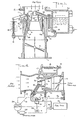
- the self-regulating variable-Venturi structure of the type shown in Fig.1 is a three-stage structure having a tubular casing 10 into which an air stream at atmospheric pressure is introduced.
- the lower end of casing 10 is coupled to the intake manifold 11 of the internal combustion engine through a duct having a foot- operated throttle 12 therein.
- a duct having a foot- operated throttle 12 therein.
- the invention is not limited to the three-stage structure shown herein, and that is is applicable to other forms of variable Venturi-structures.
- a stationary ring 13 having an external Venturi contour.
- a cylindrical booster 15 mounted coaxially within the casing 10 is a cylindrical booster 15 having an internal Venturi configuration to define a primary passage PP.
- the Venturi structure further includes cylindrical spool 16 interposed between booster 15 and ring 13.
- the outer surface of spool 16 is a true cylinder, whereas the contoured inner surface has a Venturi configuration and forms with the outer surface of booster 15 a second Venturi passage SP whose inlet. has a parabolic formation leading to a constricted throat.
- the value of a parabolic surface lies in the linear change in cross-sectional area that occurs with linear axial movement of spool 16 in response to the hydrodynamic force imposed thereon.
- the exterior surface of spool 16 while having a uniform cylindrical form, defines an annular tertiary Venturi passage TP in conjunction with the throat of the Venturi configured casing ring 13 which has a constant cross section in all axial positions of spool 16 to provide an ideal air metering means.
- the interior shape and axial position of spool 16 determines the air velocity vs. cross-sectional area characteristics of the multiple Venturis defined by (a) the exterior surface of spool 16 with respect to Venturi ring 13, (b) the interior surface of spool 16 respect to the outlet end of booster 15, and (c) the interior surface of booster 15 at this end.
- the total of the areas of all passages taken in the reference plane of the outlet end of booster 15 is the effective throat of the composite structure. The area of this effective throat therefore varies as the spool is axially shifted.
- the outer surface of spool 16 is provided at diametrically-opposed positions with two pairs of guide ribs or fins 16A-16B and 16C-16D which are slidably received in Venturi ring 13 and the interior of tubular casing 10.
- Spool 16 is provided with an extension 16B' of rib 16B to serve as an upper handle which is linked to one end of a crank 17 pivotally mounted on a bracket 14 secured to the exterior wall of Venturi casing 10.
- the other end of crank 17- is coupled to a helical tension spring 18 which is anchored on bracket 14 by means of a set screw 19 serving to adjust the spring tension.
- spool 16 is spring biased, the spool being normally maintained by the spring at its uppermost axial position at which the effective throat defined by spool 16 and booster 15 has a minimum opening. As spool 16 moves downwardly, the opening of this effective throat is progressively enlarged.
- Adjacent casing 10 is a liquid fuel float chamber or reservoir 20, the upper end of which is vented through an opening 21 leading into the air inlet 22 of the Venturi structure.
- Fuel is drawn by induction from chamber 20 through a vertical passage 23 having a fuel jet orifice 24 at its lower end, the upper end of tube 23 communicating through a connecting duct 25 terminating in a Venturi nozzle 26 which is supported by the duct coaxially within booster 15 of the Venturi structure.
- Air for dispersing the fuel is introduced into fuel tube 23 by way of an air induction tube.27, whose inlet terminates in the fuel tube below the normal fuel level.
- Inlet 29 of the air-tube communicates with the air inlet 22 of the Venturi structure.
- the differential pressure created between inlet air.pressure P 1 and the effective throat pressure P 2 acts on the fuel nozzle 26 and its connecting passage 25 to fuel tube 23 to draw fuel through jet-orifice 24 and air through tube 27.
- Air is injected into the fuel before the fuel is fed into the carburetor, the injected air bringing about a liquid fuel dispersion which promotes vaporization and reduces the fuel density, which in turn facilitates control of fuel "lag".
- the air/fuel dispersion is proportioned and maintained by the fixed orifices of fuel and air tubes, the quantity of dispersion induced into the primary passage depending on the prevailing pressure differential of air input pressure (P 1 ) less the effective throat pressure (P 2 ).
- the present invention is not limited to a helical tension spring as shown; for the spring may be in conical, torsional, leaf and in any other structural form producing a deflection which is proportional to the applied load.
- the ratio of load to spring deflection is known as the spring rate or spring constant.
- the axial displacement in response to the hydrodynamic force imposed therein depends on the prevailing mass-flow rate.
- the annular throat and differential pressure tap P2 of the tertiary passage TP lies in the same plane as the annular throat of the secondary passage SP and at the outlet of the primary passage defined by booster 15 which also lies in this plane. Consequently, an axial shift in spool 16 results in a change in the opening of the throat in secondary passage SP, resulting in a change in pressure P2 developed at the effective throat of the structure.
- Pressure P2 acts through booster 15 and nozzle 26 in fuel tube 25 in a manner whereby the amount of fuel drawn out of the reservoir through nozzle 26 is proportional to the mass of the air-fuel mixture.
- effective throat pressure P2 compensates for the density of the mixture, and the amount of fuel intermingled with the air is varied accordingly.
- the self-regulating variable venturi structure acts to modulate the fuel-air ratio to optimize this ratio for the conditions which prevail throughout the full operating range of the engine, all expedients heretofore required for this purpose being obviated by the invention.
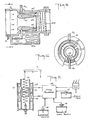
- Fig. 3 there is shown a modified form of venturi structure in which the casing 10 has no venturi ring on its inner surface as in Fig. 1, the inner surface in this instance being a pure cylinder. It will be seen that the effective throat EF lies in a plane which passes through the outlet end of booster 15 (as in F ig: 1 ), the size of this throat and the pressure P2 depending on the axial position of spool 16.
- the cylindrical interior surface of casing 10 is somewhat better adapted for the guided movement of the axially-shiftable spool by means of external ribs than a surface having a Venturi ring therein.
- the uniform tertiary passage TP defined by the cylindrical interior surface the throat of the casing ring 13 of casing 10 and the cylindrical outer surface of spool 16 provides an air flow passage which in the context of induction carburetion serves only to prevent wetting of the surface and to aid in vaporization.
- Fig. 3 is essentially the same as in Fig. 1, except that in Fig. 3 fuel is not fed into booster 15 by way of a Venturi nozzle but by means of an inlet duct 25' connected to duct 23.
- a fuel supply wherein pressurized fuel is fed, as shown in Fig. 4, to nozzle Venturi 26 through an injection nozzle 28.
- a fuel pressure feed is employed in which fuel from a tank 29 is forced by pump 30 through a solenoid shut-off valve 30' and a pressure-regulated flow-control valve 31 to nozzle 28. Priming for engine starting is by means of a solenoid bypass valve 32 controlled by a timing relay 33.
- a vacuum amplifier 34 is provided of the type disclosed in my U.S. Patent 4,308,835 which responds to three pressure variables, the first being pressure P 1 picked up at the inlet to the Venturi structure.
- the second pressure P 2 is picked up at the throat of the Venturi structure.
- the third pressure P 3 is the negative or vacuum pressure picked up at the intake manifold 11 to which the Venturi is coupled.
- Vacuum amplifier 34 yields an output pressure P 4 which is derived from the intake manifold pressure P 3 as modulated by the difference between inlet pressure P 1 and effective throat pressure P 2 . Output pressure P 4 is applied to valve 31 to effect an adjustment thereof to control the injecting fuel supply accordingly.
- An accumulator 35 provides a continuous supply of vacuum power to vacuum amplifier 34.
- the spool is axially shifted in response to the hydrodynamic force imposed thereon, the resultant pressure differential produced in the Venturi acting to modulate the injected fuel feed accordingly.
- All of the interacting and interrelated variables involved in the behavior of the engine are taken into account to automatically regulate the ratio of air-to-fuel throughout the full spectrum of the prevailing speed and load conditions encountered under both ordinary and extraordinary conditions to optimize combustion efficiency.
- the automatic Venturi structure may be incorporated, as shown in Fig. 5, in a typical double barrel carburetor with a dual throttle. This provides increased capacity in a compact arrangement.
- each barrel includes a Venturi structure and a fuel jet supplied from a common reservoir, the structure having an axially-shifted spool 36 and a throttle 37, the two throttles being ganged for concurrent operation.
- the two spools 36 are ganged by means of a cross bar 38 coupled-to one end of a crank 39 whose other end is coupled to a spring 40 so that the spring is common of both spools and the dual variable-Venturi structures operate in unison.
- each barrel (B and B 2 ) includes a totally independent automatic Venturi structure, programmed spring, fuel supply and modulating devices and throttle valves.
- the essential difference resides in the linking of the throttle blades 41 and 42 to the pedal rod 43 or manual operator so that one barrel throttle opens first while at approximately 1/3 to 1/2 open position, the second barrel starts to open. And as the operator continues to open, both progress at a rate that attains full opening simultaneously.
- the second barrel closes first reaching full closure while the first barrel throttle is at its 1/3 to 1/2 open position, and the first throttle 41 closes to the idle stop position.
- the important consideration in this application requires that both barrels and throttles supply a common plenum of central intake manifold. For divided manifolds two such progressive double barrel arrangements must be applied.
- Fig. 6 illustrates a suitable progressive linkage in which the first barrel throttle 41 is linked to the foot pedal operating rod 43 which controls throttle 41 in a conventional manner. If desired, this may be equipped with the usual idle stops, fast idle cams and stop solenoids.
- Fastened to the shaft of throttle 41 is a slotted cam-radius arm 44, in the slot of which one end of connecting rod 45 is slideably retained. The other end of rod 45 is pivotally retained in lever arm 46 which is keyed to the shaft of second throttle 42.
- Slotted cam 44 is so positioned on throttle shaft 41 that from the stop or idle position to approximately 1/3 opening, cam movement is not transmitted to rod 45 and throttle 42. The effect of this is to allow opening and closing of throttle 41 and the fueling of the engine from only one barrel until the operator causes throttle 41 to open wider, after which throttle 42 proceeds to open.
- the ratio of the radius of slot-cam 44 to that of lever 46 is such as to cause full opening of throttle 42 with a 2/3rds opening of throttle 41.
- Throttle 42 is biased by tension spring 47, whereby the closing of throttle 42 precedes the closing of throttle 41 in reverse order to the opening procedure.
- an individual spring may be provided for each Venturi spool, with the throttles for the individual carburetors ganged together.
- a system including a variable Venturi structure in accordance with the invention operating to provide on-line metering and fluidic control for use in chemical and industrial processing applications which require admixing, blending and proportioning of the fluids being processed.
- the Venturi structure is constituted by a cylindrical casing 50 provided with end flanges, making it possible to interpose the casing in the process line through which process fluid flows, the fluid input pressure to the casing being P 1 .
- Casing 50 is provided with a converging midsection 51 or throat which leads to a diverging outlet section.
- midsection 51 Slideably mounted within midsection 51 is a cylindrical spool 52 whose inner surface has a Venturi configuration.
- Midsection 51 is provided with an array of equi-spaced ribs 53 which guide the spool in the converged midsection and which define an annular space between the spool and the midsection to allow for fluid flow therethrough.
- a bar extension of spool 16 provides a spool handle 54 to which is attached a pin 55 that projects through a slot 56 in the casing.
- Pin 55 is coupled to one end of a tension spring 57 whose other end is anchored by an adjustable eye screw 58 mounted on a bracket attached to the exterior wall of the casing.
- the spool may have an exterior Venturi configuration with guide ribs affixed thereto which slide within slots in casing 50 which then has a smooth cylindrical inner surface.
- Slot 56 forms the limit stops for axial displacement of the spool, such that at zero flow, the throat of the Venturi formed within the spool lies in a plane intersecting a tap 59 in the converging midsection 51 of the casing. From tap 59, one obtains the pressure value P 2 , this tap being located between ribs 53. Spool 52 is displaced axially by the forces imposed thereon. The countervailing spring tension imposed thereon is such that at maximum flow, the inlet end of spool 52 is positioned beyond tap 59; hence the maximum effective throat of the Venturi structure is equal to the casing throat at the converging midsection 51.
- inlet section of spool 52 may have a straight taper, it preferably is given a parabolic formation, as shown, so that a linear change in cross-sectional area results from a linear axial displacement of the spool in response to the hydrodynamic forces impinging thereon.
- An upstream tap 60 is provided to yield the input static pressure P Consequently, the pressure differential between tap 60 and tap 59 (P 1 -P 2 ) is proportional to the volumetric flow, as in a conventional Venturi.
- the hydrodynamic flow is constituted both by the surface friction and a force in the downstream direction generated by the Venturi interior surface of the spool, this being analogous to that of an air or hydro-foil. Three forces act to displace the spool against the tension of spring 57 which seeks to hold the spool at its upstream limit position.
- the magnitude of the hydrodynamic force is proportional both to the instantaneous (P 1- P 2 ) differential pressure and to the extent of axial spool displacement, this magnitude reflecting the mass-volume of the fluid being metered.
- a suitable differential pressure transducer DP 1 coupled to taps 59 and 60 one may translate the pressure differential (P 1 -P 2 ) into a signal providing a reading of mass-volume.
- a displacement transducer DP 2 mechanically coupled to pin 55 one may obtain a like reading. This mass-volume reading may be used to effect process control for proportioning, blending or mixing purposes.
- the displacement transducer DP 2 is of the inductive type and the displacement spool 52' has a Venturi configuration both in the exterior and interior surfaces thereof in order to enhance the sensitivity of the spool to applied hydrodynamic forces. This is particularly useful for metering gases and light fluids.
- the external bias spring 57 one may provide an internal tension spring 57A which engages the outlet end of spool 26, this being useful for above- atmospheric pressure systems.
- an adjustable rate spring force unit is applied as the countervailing force on the Venturi spool.
- spring 60 opertes within a plastic or non-magnetic guide tube 61.
- a ferromagnetic ring armature 62 Surrounding the spring is a ferromagnetic ring armature 62, armature 61 being secured thereto at its midsection. Wound about the upper end of guide tube 61 is a first coil 63, and about its lower end is a second coil 64.
- the spring rate may be controlled by a microprocessor 65 which is responsive to data derived from various sensors such as the Oxygen-exhaust-sensor 66 from the engine exhaust which produces a signal indicative of air-fuel ratio. Also fed into the microprocessor are signals derived from other operating conditions, such as temperature sensor 67, rpm sensor 68 and intake manifold pressure sensor 69. Microprocessor 65, whose output controls the energization of coils 63 and 64, is programmed to modulate the spring rate in response to the sensed conditions to modify the air-fuel ratio accordingly.
- microprocessor 65 receives signals from engine operation sensors, as in the automatic Venturi system for the carburetion system shown in Fig. 11. However, in this instance, since fuel flow is externally controlled in accordance with differential-pressure P 1 -P 2 , a differential-pressure transducer DP 1 acts to provide this signal to microprocessor 65, the output of which is programmed to control a fuel-flow valve 70 as well as the spring rate of spool spring 60.
- the device shown in Fig. 13 provides for a reduction or an increase in the countervailing spring force to cause enrichment or weakening of the fuel-air ratio.
- This device which is shown in conjunction with a variable Venturi structure of the types illustrated in Figs. 1, 3 and 4 consists of vacuum diaphragm motor 71 whose internal spring 76 and external spring 77 acts on the diaphragm contained in a hermetically-sealed chamber 72 to more or less extend the motor shaft 73 to which the diaphragm is linked. At zero vacuum, the force of springs 76 and 77 is greater than the maximum tension of the Venturi spool spring 18.
- motor shaft 73 is pinned at one end through a slot in a lever 74 whose other end is pivotally fastened to casing 10.
- the opposite end of the spool spring 18 from the crank arm 17 is fastened to lever 74 at a point intermediate the pivot and shaft 73, whereby movement of shaft 73 in response to motor actuation increases the tension of spring 18 with decreasing vacuum, or decreases tension with increasing vacuum.
- Vacuum chamber 72 of motor 71 is connected by a tube 75 to the intake manifold of the engine.
- An alternative vacuum motor arrangement is shown in dotted lines in an arrangement whereby shaft 73 of motor 71 acts directly on spring 18.
- Another useful modification is to apply to a vacuum amplifier (not shown) the pressure values P 1 and P 2 derived from the Venturi structure, and to have the differential of P 1 and P 2 modulate in the amplifier pressure valve P 3 taken from the intake manifold to produce an output pressure P 4 which is supplied to vacuum motor 71 to modulate the spring rate as a function of air flow. This is especially useful for supercharged systems of pressurized air and in throttle valves'ahead of the Venturi structure.
- variable Venturi structures in accordance with the invention are effective in any orientation suitable to the application therefor.
- a hollow spool is shown with an internal Venturi configuration
- the axial displacement element may be in solid plug form with an external Venturi configuration.
Landscapes
- Engineering & Computer Science (AREA)
- Physics & Mathematics (AREA)
- Fluid Mechanics (AREA)
- General Physics & Mathematics (AREA)
- Chemical & Material Sciences (AREA)
- Combustion & Propulsion (AREA)
- Mechanical Engineering (AREA)
- General Engineering & Computer Science (AREA)
- Control Of The Air-Fuel Ratio Of Carburetors (AREA)
Priority Applications (1)
| Application Number | Priority Date | Filing Date | Title |
|---|---|---|---|
| EP83302569A EP0124666A1 (fr) | 1983-05-06 | 1983-05-06 | Système à commande fluidique comportant un venturi variable |
Applications Claiming Priority (1)
| Application Number | Priority Date | Filing Date | Title |
|---|---|---|---|
| EP83302569A EP0124666A1 (fr) | 1983-05-06 | 1983-05-06 | Système à commande fluidique comportant un venturi variable |
Publications (1)
| Publication Number | Publication Date |
|---|---|
| EP0124666A1 true EP0124666A1 (fr) | 1984-11-14 |
Family
ID=8191145
Family Applications (1)
| Application Number | Title | Priority Date | Filing Date |
|---|---|---|---|
| EP83302569A Ceased EP0124666A1 (fr) | 1983-05-06 | 1983-05-06 | Système à commande fluidique comportant un venturi variable |
Country Status (1)
| Country | Link |
|---|---|
| EP (1) | EP0124666A1 (fr) |
Cited By (7)
| Publication number | Priority date | Publication date | Assignee | Title |
|---|---|---|---|---|
| GB2169347A (en) * | 1985-01-07 | 1986-07-09 | Ford Motor Co | Single point fuel injection i.c. engine throttle body |
| EP0701052A1 (fr) * | 1994-09-12 | 1996-03-13 | Harold George Abbey | Dispositif d'alimentation d'un mélange air-combustible à un moteur à combustion interne |
| AT507011B1 (de) * | 2009-06-25 | 2011-07-15 | Avl List Gmbh | Brennkraftmaschine mit einem einlasssystem |
| DE102014110556B3 (de) * | 2014-07-25 | 2015-09-03 | Sick Engineering Gmbh | Vorrichtung zur Durchflussmessung |
| WO2016193681A1 (fr) * | 2015-05-29 | 2016-12-08 | Gm Flow Measurements Services Limited | Appareil amélioré de mesure d'écoulement et procédé d'utilisation |
| CN113187914A (zh) * | 2021-04-28 | 2021-07-30 | 北京航空航天大学 | 一种大范围流量调节的矩形截面可调汽蚀文氏管 |
| CN115306587A (zh) * | 2022-07-28 | 2022-11-08 | 西安航天动力研究所 | 一种液体火箭发动机汽蚀管稳定套接连接结构 |
Citations (8)
| Publication number | Priority date | Publication date | Assignee | Title |
|---|---|---|---|---|
| FR564576A (fr) * | 1924-01-05 | |||
| US1612320A (en) * | 1921-07-22 | 1926-12-28 | Herman D Schroeder | Carburetor |
| US2205027A (en) * | 1937-11-20 | 1940-06-18 | Velma Pearl Benner | Compensating carburetor |
| DE1097155B (de) * | 1958-05-21 | 1961-01-12 | Esslingen Maschf | Messdruckgeber zur Mengenmessung stroemender Medien in der Druckleitung einer Pumpanlage |
| US3398937A (en) * | 1966-07-08 | 1968-08-27 | Gen Motors Corporeation | Carburetor |
| US4112757A (en) * | 1976-08-16 | 1978-09-12 | The Secretary Of State For Industry In Her Britannic Majesty's Government Of The United Kingdom Of Great Britain And Northern Ireland | Flowrate meters |
| US4308835A (en) * | 1980-01-25 | 1982-01-05 | Abbey Harold | Closed-loop fluidic control system for internal combustion engines |
| US4387685A (en) * | 1976-10-08 | 1983-06-14 | Abbey Harold | Fluidic control system including variable venturi |
-
1983
- 1983-05-06 EP EP83302569A patent/EP0124666A1/fr not_active Ceased
Patent Citations (9)
| Publication number | Priority date | Publication date | Assignee | Title |
|---|---|---|---|---|
| FR564576A (fr) * | 1924-01-05 | |||
| US1612320A (en) * | 1921-07-22 | 1926-12-28 | Herman D Schroeder | Carburetor |
| US2205027A (en) * | 1937-11-20 | 1940-06-18 | Velma Pearl Benner | Compensating carburetor |
| DE1097155B (de) * | 1958-05-21 | 1961-01-12 | Esslingen Maschf | Messdruckgeber zur Mengenmessung stroemender Medien in der Druckleitung einer Pumpanlage |
| US3398937A (en) * | 1966-07-08 | 1968-08-27 | Gen Motors Corporeation | Carburetor |
| US4112757A (en) * | 1976-08-16 | 1978-09-12 | The Secretary Of State For Industry In Her Britannic Majesty's Government Of The United Kingdom Of Great Britain And Northern Ireland | Flowrate meters |
| US4387685A (en) * | 1976-10-08 | 1983-06-14 | Abbey Harold | Fluidic control system including variable venturi |
| US4387685B1 (en) * | 1976-10-08 | 1998-02-03 | Abbey Harold | Fluidic control system including variable venturi |
| US4308835A (en) * | 1980-01-25 | 1982-01-05 | Abbey Harold | Closed-loop fluidic control system for internal combustion engines |
Cited By (9)
| Publication number | Priority date | Publication date | Assignee | Title |
|---|---|---|---|---|
| GB2169347A (en) * | 1985-01-07 | 1986-07-09 | Ford Motor Co | Single point fuel injection i.c. engine throttle body |
| EP0701052A1 (fr) * | 1994-09-12 | 1996-03-13 | Harold George Abbey | Dispositif d'alimentation d'un mélange air-combustible à un moteur à combustion interne |
| AT507011B1 (de) * | 2009-06-25 | 2011-07-15 | Avl List Gmbh | Brennkraftmaschine mit einem einlasssystem |
| DE112010002706B4 (de) | 2009-06-25 | 2024-05-02 | Avl List Gmbh | Brennkraftmaschine mit einem einlasssystem |
| DE102014110556B3 (de) * | 2014-07-25 | 2015-09-03 | Sick Engineering Gmbh | Vorrichtung zur Durchflussmessung |
| WO2016193681A1 (fr) * | 2015-05-29 | 2016-12-08 | Gm Flow Measurements Services Limited | Appareil amélioré de mesure d'écoulement et procédé d'utilisation |
| US10859415B2 (en) | 2015-05-29 | 2020-12-08 | Gm Flow Measurement Services Limited | Flow measurement apparatus and method of use |
| CN113187914A (zh) * | 2021-04-28 | 2021-07-30 | 北京航空航天大学 | 一种大范围流量调节的矩形截面可调汽蚀文氏管 |
| CN115306587A (zh) * | 2022-07-28 | 2022-11-08 | 西安航天动力研究所 | 一种液体火箭发动机汽蚀管稳定套接连接结构 |
Similar Documents
| Publication | Publication Date | Title |
|---|---|---|
| US4387685A (en) | Fluidic control system including variable venturi | |
| US4308835A (en) | Closed-loop fluidic control system for internal combustion engines | |
| US4535728A (en) | Fuel feed control system and control valve for dual fuel operation of an internal combustion engine | |
| US5377646A (en) | Liquid petroleum gas fuel delivery systems | |
| US4250856A (en) | Fuel-air ratio automatic control system using variable venturi structure | |
| US4224908A (en) | Apparatus and system for controlling the air-fuel ratio supplied to a combustion engine | |
| US4246875A (en) | Apparatus and system for controlling the air-fuel ratio supplied to a combustion engine | |
| US3965221A (en) | Fluid flow device and liquid metering | |
| US3944634A (en) | Carburetor idling system | |
| US4895184A (en) | Fluid servo system for fuel injection and other applications | |
| NZ204869A (en) | Air-flow and throttle responsive gas valve for dual fuel system fitted to diesel engine | |
| JPH0116985B2 (fr) | ||
| US3721428A (en) | Constant negative-pressure carburettors | |
| US4118444A (en) | Variable venturi carburetion system | |
| US4579097A (en) | Fuel supply apparatus and method for internal combustion engines | |
| US4813394A (en) | Carburetion systems | |
| US4530805A (en) | Flow regulating carburetors | |
| JPS6111469Y2 (fr) | ||
| US4135482A (en) | Apparatus and system for controlling the air-fuel ratio supplied to a combustion engine | |
| US4056583A (en) | Variable venturi carburetor | |
| EP0124666A1 (fr) | Système à commande fluidique comportant un venturi variable | |
| US4187805A (en) | Fuel-air ratio controlled carburetion system | |
| US2128079A (en) | Carburetor | |
| US4335693A (en) | Fuel injection apparatus and system | |
| US3996906A (en) | Controlled exhaust gas fuel atomizing nozzle |
Legal Events
| Date | Code | Title | Description |
|---|---|---|---|
| PUAI | Public reference made under article 153(3) epc to a published international application that has entered the european phase |
Free format text: ORIGINAL CODE: 0009012 |
|
| AK | Designated contracting states |
Designated state(s): DE FR GB IT SE |
|
| 17P | Request for examination filed |
Effective date: 19850506 |
|
| 18R | Application refused |
Effective date: 19880509 |
|
| STAA | Information on the status of an ep patent application or granted ep patent |
Free format text: STATUS: THE APPLICATION HAS BEEN REFUSED |
|
| R18R | Application refused (corrected) |
Effective date: 19901110 |
|
| APAF | Appeal reference modified |
Free format text: ORIGINAL CODE: EPIDOSCREFNE |