EP0126540B1 - Appareil pour couper les légumes - Google Patents
Appareil pour couper les légumes Download PDFInfo
- Publication number
- EP0126540B1 EP0126540B1 EP84302470A EP84302470A EP0126540B1 EP 0126540 B1 EP0126540 B1 EP 0126540B1 EP 84302470 A EP84302470 A EP 84302470A EP 84302470 A EP84302470 A EP 84302470A EP 0126540 B1 EP0126540 B1 EP 0126540B1
- Authority
- EP
- European Patent Office
- Prior art keywords
- housing
- lower housing
- upper housing
- cutter disk
- drive shaft
- Prior art date
- Legal status (The legal status is an assumption and is not a legal conclusion. Google has not performed a legal analysis and makes no representation as to the accuracy of the status listed.)
- Expired
Links
- 235000013311 vegetables Nutrition 0.000 title claims abstract description 21
- 230000002093 peripheral effect Effects 0.000 claims description 32
- 239000013013 elastic material Substances 0.000 claims description 2
- 210000000078 claw Anatomy 0.000 description 2
- 238000005406 washing Methods 0.000 description 2
- 240000007124 Brassica oleracea Species 0.000 description 1
- 235000003899 Brassica oleracea var acephala Nutrition 0.000 description 1
- 235000011301 Brassica oleracea var capitata Nutrition 0.000 description 1
- 235000001169 Brassica oleracea var oleracea Nutrition 0.000 description 1
- 244000000626 Daucus carota Species 0.000 description 1
- 235000002767 Daucus carota Nutrition 0.000 description 1
- 244000088415 Raphanus sativus Species 0.000 description 1
- 235000006140 Raphanus sativus var sativus Nutrition 0.000 description 1
- 238000004140 cleaning Methods 0.000 description 1
- 238000010276 construction Methods 0.000 description 1
Images


Classifications
-
- B—PERFORMING OPERATIONS; TRANSPORTING
- B26—HAND CUTTING TOOLS; CUTTING; SEVERING
- B26D—CUTTING; DETAILS COMMON TO MACHINES FOR PERFORATING, PUNCHING, CUTTING-OUT, STAMPING-OUT OR SEVERING
- B26D1/00—Cutting through work characterised by the nature or movement of the cutting member or particular materials not otherwise provided for; Apparatus or machines therefor; Cutting members therefor
- B26D1/01—Cutting through work characterised by the nature or movement of the cutting member or particular materials not otherwise provided for; Apparatus or machines therefor; Cutting members therefor involving a cutting member which does not travel with the work
- B26D1/12—Cutting through work characterised by the nature or movement of the cutting member or particular materials not otherwise provided for; Apparatus or machines therefor; Cutting members therefor involving a cutting member which does not travel with the work having a cutting member moving about an axis
- B26D1/25—Cutting through work characterised by the nature or movement of the cutting member or particular materials not otherwise provided for; Apparatus or machines therefor; Cutting members therefor involving a cutting member which does not travel with the work having a cutting member moving about an axis with a non-circular cutting member
- B26D1/26—Cutting through work characterised by the nature or movement of the cutting member or particular materials not otherwise provided for; Apparatus or machines therefor; Cutting members therefor involving a cutting member which does not travel with the work having a cutting member moving about an axis with a non-circular cutting member moving about an axis substantially perpendicular to the line of cut
- B26D1/28—Cutting through work characterised by the nature or movement of the cutting member or particular materials not otherwise provided for; Apparatus or machines therefor; Cutting members therefor involving a cutting member which does not travel with the work having a cutting member moving about an axis with a non-circular cutting member moving about an axis substantially perpendicular to the line of cut and rotating continuously in one direction during cutting
- B26D1/29—Cutting through work characterised by the nature or movement of the cutting member or particular materials not otherwise provided for; Apparatus or machines therefor; Cutting members therefor involving a cutting member which does not travel with the work having a cutting member moving about an axis with a non-circular cutting member moving about an axis substantially perpendicular to the line of cut and rotating continuously in one direction during cutting with cutting member mounted in the plane of a rotating disc, e.g. for slicing beans
-
- B—PERFORMING OPERATIONS; TRANSPORTING
- B26—HAND CUTTING TOOLS; CUTTING; SEVERING
- B26D—CUTTING; DETAILS COMMON TO MACHINES FOR PERFORATING, PUNCHING, CUTTING-OUT, STAMPING-OUT OR SEVERING
- B26D3/00—Cutting work characterised by the nature of the cut made; Apparatus therefor
- B26D3/24—Cutting work characterised by the nature of the cut made; Apparatus therefor to obtain segments other than slices, e.g. cutting pies
- B26D3/26—Cutting work characterised by the nature of the cut made; Apparatus therefor to obtain segments other than slices, e.g. cutting pies specially adapted for cutting fruit or vegetables, e.g. for onions
-
- B—PERFORMING OPERATIONS; TRANSPORTING
- B26—HAND CUTTING TOOLS; CUTTING; SEVERING
- B26D—CUTTING; DETAILS COMMON TO MACHINES FOR PERFORATING, PUNCHING, CUTTING-OUT, STAMPING-OUT OR SEVERING
- B26D7/00—Details of apparatus for cutting, cutting-out, stamping-out, punching, perforating, or severing by means other than cutting
Definitions
- the present invention relates to a device for cutting or slicing vegetables such as carrots, radishes, cabbages, and the like, the device being operated manually.
- a conventional cutting device normally comprises a cup-shaped housing, a cutter disk provided at an opening portion of the housing and rotatable about the axis of the housing, a cover mounted on the opening portion, and a manually operated handle connected to the cutter disk and supported by the cover.
- a vegetable to be cut is applied to an upper face of the cutter disk, and is cut in such a manner that the cut pieces remain in the housing.
- the cover, the cutter disk, and the housing can be disassembled, to enable the cut pieces of vegetable to be removed and for washing the housing and the cutter disk.
- DE-C-846,151 discloses a device for cutting vegetables and the like and comprises a cup-shaped lower housing having an upper peripheral portion and an upper housing having a lower peripheral portion which is engagable with the upper peripheral portion of the lower housing.
- the upper housing includes an inlet for feeding vegetables and the like into the device and means for interconnecting the said upper and lower peripheral portions.
- a cutter disk having at least one cutter blade is rotatably mounted about an axis within the lower housing and includes an upper face confronting the inlet and a lower face which defines a storage chamber within the lower housing and beneath the cutting disk for storing cut vegetables.
- the cutter disk further includes a bore which is coaxial with the said axis of the lower housing and a drive shaft which is rotatably supported by the upper housing and serves to drive the cutter through a non-rotatable and detachable driving connection disposed within the bore. During operation and unless a locking unit is released, the cutter remains securely attached to the upper housing.
- the cutting device must be able to be easily assembled for cutting a vegetable, and easily disassembled for removing the cut pieces of vegetable from the housing, as well as for washing and cleaning the housing and other parts of the device.
- An object of this invention is to provide a vegetable cutting device that is easily assembled and disassembled.
- a vegetable cutting device attachable to a firm surface for cutting vegetables or like comestibles comprising a cup shaped lower housing having an upper peripheral portion, an upper housing having a lower peripheral portion which is engageable with the upper peripheral portion of the lower housing, an inlet formed in the upper housing, interconnecting means for detachably interconnecting the upper and lower peripheral portions and a cutter disk having at least one cutter blade mounted for rotation within the lower housing and about the axis of the upper peripheral portion, the cutter disk having an upper face which faces the inlet and a lower face which delimits a storage chamber in the interior of the lower housing, a drive means having a manually operated drive shaft which is rotatably supported by the upper housing, characterised in that:
- the upper housing is an inverted cup-shape, in that the cutter disk is detachably and rotatably supported by the lower housing and has a spindle formed with a bore which is coaxial with the axis of the lower housing and with the drive shaft, in that the bore of the spindle is non-rotatably and detachably connectable to a lower engaging portion of the drive shaft which extends into the lower housing when the housings are interconnected so that the cutter disk is centred on its axis of rotation at two axially displaced locations in the region of the lower engaging portion of the drive shaft and of a support pin located within the lower housing, and in that a fixing apparatus is attached to a lower portion of the lower housing for fixing the lower housing 2 to the said firm surface.
- FIGs 1 to 16 show a cutting device according to an embodiment of the present invention.
- a cutting device is generally indicated by reference numeral 1.
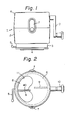
- a cup-shaped lower housing 2 for storing cut pieces of vegetable is mounted on a fixing apparatus 3 which fixes the lower housing 2 onto a base plate by a sucker member 4 manually operated by a lever 5.
- An inverted cup-shape upper housing 6 is placed on the lower housing 2 and covers an opening thereof.
- the upper housing 6 is detachably interconnected to the lower housing 2 by a pair of connecting apparatuses 7.
- a cutter disk 8 fitted with cutter blades 9 is arranged in the lower housing 2.
- the cutter disk 8 is rotatable about the central axis of the lower housing, and is rotated by a handle 10 attached outside of the upper housing 6.
- An inlet 11 is formed in the upper housing 6 for supplying the vegetable to be cut to the cutter disk 8.
- Fig. 3 shows a sectional view of the cutting device 1
- Fig. 4 shows the same in a disassembled state.
- the lower housing 2 has an upper peripheral portion 20 which defines the opening, and has a tubular guide 21 which surrounds the axis of the housing.
- a lower peripheral portion 22 of the upper housing 6 is engagable with the inside of the upper peripheral portion 20, and the lower peripheral portion 22 is fixed to the upper peripheral portion 20 by the connecting apparatus 7.
- the cutter disk 8 is detachably arranged at the opening of the lower housing 2, and a lower face thereof defines a storage chamber 23 in an interior of the lower housing 2.
- the cutter disk 8 is rotatably supported by a pin 24 mounted on a projection 25 formed on an upper plate of a casing 26 of the fixing apparatus 3. That is, the cutter disk 8 has a downward extending spindle 27 in which a bore 28 and a hole 29 are formed, while the projection 25 extends toward the hole 29 and the pin 24 rotatably engages with the hole 29.
- the pin 24 extends along the axis of the lower housing 2, and is inserted into the hole 29, which has a diameter smallerthan that of the bore 28.
- the cutter disk 8 is detachable from the pin 24.
- a washer 30 is inserted between the spindle 27 and the projection 25, to reduce friction therebetween.
- the tubular guide 21 surrounds the spindle 27 and the projection 25.
- the cutter disk 8 is driven by the handle 10 to rotate about the axis of the lower housing 2.
- a first drive shaft 31 is rotatably supported by a box 32 formed in the upper housing 6.
- the drive shaft 31 has a lower engaging portion 33 which is non-rotatably and detachably fitted into the bore 28 of the cutter disk 8. That is, the lower engaging portion 33 has a polygonal cross-section (e.g., a square cross-section), and the bore 28 has a corresponding cross-section (see Fig. 5). Therefore, when the drive shaft 31 is rotated by the handle 10, at least one flat surface of the lower engaging portion 33 engages with a flat surface of the bore 28, so that the shaft 31 rotates the cutter disk 8.
- the lower engaging portion 33 has a tapered end portion 34 which converges downward so that the lower engaging portion 33 is easily inserted into the bore 28.
- the handle 10 is rotatably attached to a side wall of the upper housing 6.
- a second drive shaft 35 connected to the handle 10 is provided with a second bevel gear 36 which is housed in the box 32 and engages with a first bevel gear 37 fixed onto the first drive shaft 31.
- a drive means is constructed from the first and second drive shafts 31, 35, the first and second bevel gears 37,36, and the handle 10.
- a pair of slots 40 are formed in the cutter disk 8, these slots extend in a substantially radial direction, as shown in Fig. 5.
- Each cutter blade 9 is arranged in the slots 40, respectively, and is fixed to a lower face of the disk 8 by a retainer plate 41 and a screw 42, as shown in Fig. 6.
- a cutting edge 49 of the cutter blade 9 projects from the upper surface of the cutter disk 8 in such a manner that the edge 49 will cut or slice a vegetable.
- the retainer plate 41 is supported by a rim 43 formed on the lower face of the disk 8.
- the cutter disk 8 has annular ribs 44, 45 which protrude from the lower face thereof. These ribs 44, 45 are concentric with and provide rigidity to the disk 8.
- the upper housing 6 has a downward extending tubularwall 46 terminating in the vicinity of an upper face of the disk 8.
- the tubular wall 46 defines the inlet 11, which the upper face of the disk 8 faces.
- the inlet 11 is formed at a half part of the upper housing 6, but is not formed at the box. Thus, the inlet 11 is opened along the rotational direction of the disk 8.
- a pushdown member 47 may be provided for pressing a vegetable inserted in the inlet 11 onto the upper face of the cutter disk 8.
- the pushdown member 47 is formed into a shape that conforms to the shape of the inlet 11, and has a head portion 48 for manual handling, as shown in Figs. 7 and 8.
- the fixing apparatus 3 comprises the casing 26, the sucker member 4, and the manual lever 5, as previously mentioned, and is attached to a bottom face of the lower housing 2 by inserting claws 60 formed on a bottom surface of the lower housing 2 into holes (not shown) opened in the casing 26.
- the sucker member 4 is made of an elastic material such as a rubber, and is formed into an inverted disk-shape.
- the sucker member 4 has a concave central portion 50 and a ring-shaped peripheral flat portion 51, a lower surface of which will make a sealed contact with a base plate.
- An upper surface of the flat portion 51 is supported by the casing 26 so that the lower surface of the flat portion 51 makes a sealed contact with the base plate.
- the sucker member 4 is formed with an upward extending first annular rib 52 in contact with the casing 26, and an upward extending second annular rib 53 radially and outwardly spaced from the first annular rib 52.
- the casing 26 has a downward extending enclosure 54 at a peripheral portion, and a downward extending annular wall 55 inside of the enclosure 54.
- a lower end portion of the annular wall 55 is in contact with the upper face of the flat portion 51 of the sucker member 4, and an outer surface of the annular wall 55 is engaged with the inside of the first annular rib 52.
- the manual lever 5 penetrates the annular wall 55, and a knob 56 of the lever 5 projects from the enclosure, whereby the lever 5 is rotatably supported bythe casing 26.
- the manual lever 5 has a crank portion 57 connected to a joint member 58 fixed to the central portion of the sucker member4.
- the joint member 58 has a disk plate 61 fixed to the central portion of the sucker member 4 and a projection 62 extending upward on the disk plate 61, and a hole 63 is formed in the projection 62.
- the crank portion 57 of the lever 5 is inserted in the hole 63 of the joint member 58.
- the lever 5 actuates the central portion up and down as follows.
- Fig. 9 shows a state in which the central portion of the sucker member 4 is lowered, that is, the fixing apparatus 3 is not operative. l this state, the crank portion 57 is located in a lower position so that the joint member 58, i.e., the central portion of the sucker member 4 is lowered. Consequently, a space 64, defined by the sucker member4 and the base plate, has a relatively small volume. To the contrary, if the lever 5 is rotated about 180°, the crank portion 57 is moved upward so that the central portion of the sucker member4 is raised, as shown in Fig. 10.
- the volume of the space 64 is enlarged so that a vacuum is formed in the space 64, and the flat portion 51 of the sucker member 4 makes a sealed contact with the base plate, whereby the fixing apparatus 3 sticks to the base plate.
- the first annular rib 52 engages with the outer surface of the wall 55, the flat portion 51 does not move inwards, and, since the flat portion 51 has a relatively wide breadth and is formed with the second annular rib 53, the rigidity of the flat portion 51 is increased and the flat portion 51 is placed in firm contact with the base plate, and will not separate from the base plate.
- the fixing apparatus 3 is released from the base plate by rotating the lever 5 to a position shown in Fig. 9.
- the cutting device comprises the upper housing 6, the cutter disk 8, the lower housing 2, and the fixing apparatus 3, and these components can be disassembled as shown in Fig. 4.
- the upper housing 6 is removed from the lower housing 2 and the cutter disk 8 by releasing the connecting apparatuses7 (see Fig.1, described in detail hereinafter) and drawing the engaging portion 33 from the bore 28 of the cutter disk 8.
- the cutter disk 8 is removed by lifting it off of the pin 24.
- the lower housing 2 is detached from the fixing apparatus 3 by drawing the claws 60 from the holes formed in the casing 26. In this disassembling operation, the fixing apparatus 3 may remain in sealed contact with the base plate.
- the cutter disk 8 can be detached from the lower housing 2, and the lower housing 2 can be removed from the fixing apparatus 3, any cut pieces of vegetable stored in the lower housing 2 are easily removed, and it is easy to wash the lower housing 2 after use.
- the cutting device can be quickly re-assembled by mounting the lower housing 2 on the fixing apparatus 3, arranging the cutter disk 8 in the lower housing 2, and engaging the upper housing with the lower housing 2.
- the cutter disk 8 is easily changed for another kind of cutter disk according to the purpose for which the device will be used.
- the spindle 27 is rotatably supported by the projection 25 and the pin 24, and the bore 28 is engaged with the lower engaging portion 33 of the drive shaft 31. That is, the cutter disk 8 is supported at two points, ensuring a stable rotation of the cutter disk 8 when cutting a vegetable.
- the lower housing 2, the upper housing 6, the disk 8, the casing 26, the pin 24, the bevel gears 36, 37, the lower engaging portion 33 of the shaft, the handle 10, and the pushdown member 47 are all made of plastic.
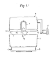
- Figure 11 to 16 show the construction and operation of the connecting apparatus 7,
- the lower peripheral portion 70 of the upper housing 6 is fitted into the upper peripheral portion 71 of the lower housing 2.
- the projection 72 formed on the lower peripheral portion 70 engage with L-shaped slots 73 formed on the upper peripheral portion 71, by moving the upper housing 6 downward along the axis thereof.
- the L-shaped slot 73 has a substantially vertical portion 74 and a substantially horizontal portion 75, and the projection 72 enters the vertical portion first.
- the upper housing 6 is then slightly rotated about the axis thereof, in relation to the lower housing 2, so that the connecting apparatuses 7 lock both the housings 2 and 6, as described later.
- a pair of connecting apparatuses 7 are mounted on the upper housing 6 at opposite sides (see Fig. 2), respectively, and prevent the projections 72 from being dislodged from the L-shaped slots 73.
- the connecting apparatus 7 has a pawl 80 engagable with the vertical portion 74 of the L-shaped slot 73.
- the pawl 80 is located in the upper housing 6, and projects therefrom through an opening 81 formed in the lower peripheral portion 70, so that the pawl 80 engages with the vertical portion 74 of the L-shaped slot 73, as shown in Figs. 12 and 13.
- the connecting apparatus 7 comprises an inner member 82 arranged on an inner wall of the upper housing 6, an outer member, i.e., a manual lever83 arranged on an outer wall of the upper housing 6, and a plate-shaped spring 84 inserted between the upper housing 6 and the manual lever 83, as shown in Figs. 14 and 15. While the upper housing 6 is formed with a first hole 85 and a second hole 86 vertically aligned with and spaced downward from the first hole 85, the manual lever 83 has a first connecting rod member 87 and a second connecting rod member 88 extending through the first hole 85 and the second hole 86, respectively.
- the first connecting rod member 87 engages with an opening 89 formed in the inner member 82, and the second connecting rod member 88 is fixed to a surface of the inner member 82 by a screw 90, whereby the manual lever 83 and the inner member 82 are interconnected to each other.
- the inner member 82 and manual lever 83 are pivotally supported on the upper housing 6 with respect to the first connecting rod member87, and are biased outwardly by the plate spring 84.
- the pawl 80 is formed on the inner member 82 as shown in Fig. 16, and is located beneath the second connecting rod member 88.
- the pawl 80 has an inclined surface 91 directed downward, so that the pawl 80 can slide on an inner surface of the lower housing 2 when the upper housing 6 is fitted in the lower housing 2.
- the plate spring 84 is bent into an arc-like shape in a free state, as shown in Fig. 16.
- the plate spring 84 has, at opposed ends thereof, a first cutaway portion 92 and a second cutaway portion 93, which are engagable with the first connecting rod member 87 and the second connecting rod member 88, respectively.
- the spring 84 is mounted between the manual lever 83 and the upper housing 6 so that a convex surface of the spring 84 is in contact with the manual lever 83.
- the plate spring 84 is attached to the manual lever 83, and then the lever 83 with the spring 84 attached is mounted on the upper housing 6; the first and second rod members 87, 88 being inserted in the first and second holes 85, 86, respectively.
- the opening 89 is engaged with the rod member 87, and an inner periphery of the opening 89 is fitted in a notch 94 of the rod member 87, then the inner member 82 is fixed to the second rod member 88 by the screw 90.
- the connecting apparatus 7 In a non-operative state, the connecting apparatus 7 is biased outward so that a lower end of the manual lever 83 is situated away from the lower peripheral portion of the upper housing 6, and the pawl 80 is projected through the opening 81.
- the manual lever 83 is longer than the inner member 82, so the pawl 80 is hidden by the lower end of the lever 83 (see Fig. 12).
- the projection 72 When the upper housing 6 is engaged with the lower housing 2, first, the projection 72 is fitted to the vertical portion 74 of the L-shaped slot 73, then the upper housing 6 is rotated until the pawl 80 engages with the horizontal portion 74 of the L-shaped slot 73 and the projection 72 enters the horizontal portion 75 of the slot 73. In this state, the pawl 72 prevents the upper housing 6 from rotating relative to the lower housing 2, so that the projection 72 remains engaged with the L-shaped slot 73 to prevent the upper housing 6 from being removed from the lower housing 2.
- the manual lever 83 is manually pushed toward the upper housing 6, against the spring 84, as shown in Fig. 15.
- the pawl 80 is released from the L-shaped slot 73, as shown in Fig. 15, and the upper housing 6 is rotated so that the projection 72 engages with the vertical portion 74 of the L-shaped slot 73.
- the upper housing 6 is then moved upward while the projection 72 is guided by the vertical portion 74, and the housing 6 is detached from the lower housing 2.
- a depression 95 may be formed at a lower portion of the manual lever 83 to facilitate manual pushing.
Landscapes
- Life Sciences & Earth Sciences (AREA)
- Forests & Forestry (AREA)
- Engineering & Computer Science (AREA)
- Mechanical Engineering (AREA)
- Food-Manufacturing Devices (AREA)
- Apparatuses For Bulk Treatment Of Fruits And Vegetables And Apparatuses For Preparing Feeds (AREA)
Claims (19)
Priority Applications (1)
| Application Number | Priority Date | Filing Date | Title |
|---|---|---|---|
| AT84302470T ATE34115T1 (de) | 1983-05-19 | 1984-04-11 | Vorrichtung zum schneiden von gemuese. |
Applications Claiming Priority (6)
| Application Number | Priority Date | Filing Date | Title |
|---|---|---|---|
| JP1983073718U JPS59178940U (ja) | 1983-05-19 | 1983-05-19 | 野菜類切断器 |
| JP73718/83 | 1983-05-19 | ||
| JP12133083U JPS6029917U (ja) | 1983-08-05 | 1983-08-05 | 吸着盤装置 |
| JP121330/83 | 1983-08-05 | ||
| JP156880/83 | 1983-10-12 | ||
| JP15688083U JPS6066495U (ja) | 1983-10-12 | 1983-10-12 | 卓上用手動切削器類のカバ−固定装置 |
Publications (2)
| Publication Number | Publication Date |
|---|---|
| EP0126540A1 EP0126540A1 (fr) | 1984-11-28 |
| EP0126540B1 true EP0126540B1 (fr) | 1988-05-11 |
Family
ID=27301296
Family Applications (1)
| Application Number | Title | Priority Date | Filing Date |
|---|---|---|---|
| EP84302470A Expired EP0126540B1 (fr) | 1983-05-19 | 1984-04-11 | Appareil pour couper les légumes |
Country Status (4)
| Country | Link |
|---|---|
| EP (1) | EP0126540B1 (fr) |
| AT (1) | ATE34115T1 (fr) |
| CA (1) | CA1214712A (fr) |
| DE (1) | DE3471034D1 (fr) |
Families Citing this family (4)
| Publication number | Priority date | Publication date | Assignee | Title |
|---|---|---|---|---|
| FR2800661A1 (fr) * | 1999-11-10 | 2001-05-11 | Gerard Tisserand | Spirale a pomme de terre |
| FR2935245B1 (fr) * | 2008-08-27 | 2010-09-17 | Seb Sa | Couvercle d'article culinaire. |
| DE202014102077U1 (de) * | 2014-05-05 | 2014-07-08 | Genius Gmbh | Vorrichtung zum Zerkleinern von Lebensmitteln |
| CN112476569A (zh) * | 2020-11-05 | 2021-03-12 | 抚州锦溪农业发展有限公司 | 一种便于调节切片厚度的农产品加工用果蔬切片机 |
Family Cites Families (5)
| Publication number | Priority date | Publication date | Assignee | Title |
|---|---|---|---|---|
| DE846151C (de) * | 1950-06-29 | 1952-08-11 | Oscar Cuepper | Verfahren und Geraet zum Zerkleinern von Zwiebeln |
| CH307581A (de) * | 1952-11-11 | 1955-06-15 | Oertli T Ag | Maschine zum Zerkleinern von Gemüsen. |
| FR1564362A (fr) * | 1967-05-17 | 1969-04-18 | ||
| US4095751A (en) * | 1977-03-25 | 1978-06-20 | Oster Corporation | Slicing and shredding apparatus |
| US4367667A (en) * | 1981-02-27 | 1983-01-11 | Cuisinarts, Inc. | French fry cutter for food processors |
-
1984
- 1984-04-11 DE DE8484302470T patent/DE3471034D1/de not_active Expired
- 1984-04-11 AT AT84302470T patent/ATE34115T1/de not_active IP Right Cessation
- 1984-04-11 EP EP84302470A patent/EP0126540B1/fr not_active Expired
- 1984-04-13 CA CA000452038A patent/CA1214712A/fr not_active Expired
Also Published As
| Publication number | Publication date |
|---|---|
| DE3471034D1 (en) | 1988-06-16 |
| ATE34115T1 (de) | 1988-05-15 |
| EP0126540A1 (fr) | 1984-11-28 |
| CA1214712A (fr) | 1986-12-02 |
Similar Documents
| Publication | Publication Date | Title |
|---|---|---|
| US4602543A (en) | Vegetable cutting device | |
| US4369680A (en) | Method and apparatus for changing slicer cutting parameters in a rotary food processor | |
| US4456185A (en) | Apparatus for treating food | |
| SK3182001A3 (en) | Removable food processing tool support system for blenders, food processors, grinders and similar apparatus | |
| JP6386209B2 (ja) | 食品処理装置 | |
| EP0126540B1 (fr) | Appareil pour couper les légumes | |
| CN116133567A (zh) | 用于食品加工设备的存放容器 | |
| US20020047060A1 (en) | Kitchen appliance having a disc which is axially movable with respect to a processing tool | |
| US4226374A (en) | Two level feed tube for food processor | |
| US5308002A (en) | Food slicer | |
| KR870000161B1 (ko) | 채소 절단 장치 | |
| JPH01153123A (ja) | 調理器のカッター装置 | |
| GB1562070A (en) | Food preparing machine | |
| JP3949645B2 (ja) | フードプロセッサー | |
| JPS6146127B2 (fr) | ||
| JPS5849736Y2 (ja) | 食品調理器の保護装置 | |
| KR0125796Y1 (ko) | 푸드 믹서 | |
| JP2535803Y2 (ja) | 調理装置 | |
| US20060118668A1 (en) | Vegetable cutting device | |
| JP2582933B2 (ja) | 調理器 | |
| KR200273181Y1 (ko) | 핸드믹서기의 회전칼날 고정결합구 | |
| JP2755720B2 (ja) | 電動調理機 | |
| JP3140940B2 (ja) | 調理器 | |
| JP3121742B2 (ja) | 調理器 | |
| JPS6034370B2 (ja) | 調理器 |
Legal Events
| Date | Code | Title | Description |
|---|---|---|---|
| PUAI | Public reference made under article 153(3) epc to a published international application that has entered the european phase |
Free format text: ORIGINAL CODE: 0009012 |
|
| 17P | Request for examination filed |
Effective date: 19840502 |
|
| AK | Designated contracting states |
Designated state(s): AT BE CH DE FR GB IT LI LU NL SE |
|
| GRAA | (expected) grant |
Free format text: ORIGINAL CODE: 0009210 |
|
| AK | Designated contracting states |
Kind code of ref document: B1 Designated state(s): AT BE CH DE FR GB IT LI LU NL SE |
|
| PG25 | Lapsed in a contracting state [announced via postgrant information from national office to epo] |
Ref country code: LI Effective date: 19880511 Ref country code: CH Effective date: 19880511 Ref country code: AT Effective date: 19880511 |
|
| REF | Corresponds to: |
Ref document number: 34115 Country of ref document: AT Date of ref document: 19880515 Kind code of ref document: T |
|
| ITF | It: translation for a ep patent filed | ||
| PG25 | Lapsed in a contracting state [announced via postgrant information from national office to epo] |
Ref country code: SE Effective date: 19880531 |
|
| REF | Corresponds to: |
Ref document number: 3471034 Country of ref document: DE Date of ref document: 19880616 |
|
| ET | Fr: translation filed | ||
| REG | Reference to a national code |
Ref country code: CH Ref legal event code: PL |
|
| PLBE | No opposition filed within time limit |
Free format text: ORIGINAL CODE: 0009261 |
|
| STAA | Information on the status of an ep patent application or granted ep patent |
Free format text: STATUS: NO OPPOSITION FILED WITHIN TIME LIMIT |
|
| PG25 | Lapsed in a contracting state [announced via postgrant information from national office to epo] |
Ref country code: GB Effective date: 19890411 |
|
| ITTA | It: last paid annual fee | ||
| PG25 | Lapsed in a contracting state [announced via postgrant information from national office to epo] |
Ref country code: LU Free format text: LAPSE BECAUSE OF NON-PAYMENT OF DUE FEES Effective date: 19890430 Ref country code: BE Effective date: 19890430 |
|
| 26N | No opposition filed | ||
| BERE | Be: lapsed |
Owner name: HONMA K.K. Effective date: 19890430 |
|
| PG25 | Lapsed in a contracting state [announced via postgrant information from national office to epo] |
Ref country code: NL Effective date: 19891101 |
|
| GBPC | Gb: european patent ceased through non-payment of renewal fee | ||
| NLV4 | Nl: lapsed or anulled due to non-payment of the annual fee | ||
| PG25 | Lapsed in a contracting state [announced via postgrant information from national office to epo] |
Ref country code: FR Free format text: LAPSE BECAUSE OF NON-PAYMENT OF DUE FEES Effective date: 19891228 |
|
| PG25 | Lapsed in a contracting state [announced via postgrant information from national office to epo] |
Ref country code: DE Effective date: 19900103 |
|
| REG | Reference to a national code |
Ref country code: FR Ref legal event code: ST |