EP0127706A1 - Methode und Apparat zur Regelung einer gebündelten Strahlenergie sowie Verfahren und Einrichtung mit dieser Methode, bzw. diesem Apparat - Google Patents
Methode und Apparat zur Regelung einer gebündelten Strahlenergie sowie Verfahren und Einrichtung mit dieser Methode, bzw. diesem Apparat Download PDFInfo
- Publication number
- EP0127706A1 EP0127706A1 EP83303165A EP83303165A EP0127706A1 EP 0127706 A1 EP0127706 A1 EP 0127706A1 EP 83303165 A EP83303165 A EP 83303165A EP 83303165 A EP83303165 A EP 83303165A EP 0127706 A1 EP0127706 A1 EP 0127706A1
- Authority
- EP
- European Patent Office
- Prior art keywords
- groups
- workpiece
- time
- successive
- controlling
- Prior art date
- Legal status (The legal status is an assumption and is not a legal conclusion. Google has not performed a legal analysis and makes no representation as to the accuracy of the status listed.)
- Granted
Links
- 238000000034 method Methods 0.000 title claims abstract description 21
- 230000005855 radiation Effects 0.000 title claims abstract description 19
- 238000003754 machining Methods 0.000 claims description 5
- 238000005520 cutting process Methods 0.000 claims description 3
- 238000005553 drilling Methods 0.000 claims description 3
- 239000000463 material Substances 0.000 claims description 3
- 238000005259 measurement Methods 0.000 claims description 3
- 238000003466 welding Methods 0.000 claims description 3
- 238000010438 heat treatment Methods 0.000 claims description 2
- 238000010894 electron beam technology Methods 0.000 abstract description 6
- 238000004804 winding Methods 0.000 description 6
- XEEYBQQBJWHFJM-UHFFFAOYSA-N Iron Chemical compound [Fe] XEEYBQQBJWHFJM-UHFFFAOYSA-N 0.000 description 4
- 230000001133 acceleration Effects 0.000 description 3
- 239000002131 composite material Substances 0.000 description 3
- 238000010276 construction Methods 0.000 description 3
- 238000010586 diagram Methods 0.000 description 2
- 229910052742 iron Inorganic materials 0.000 description 2
- 238000012545 processing Methods 0.000 description 2
- 239000011246 composite particle Substances 0.000 description 1
- 150000002500 ions Chemical class 0.000 description 1
- 238000005192 partition Methods 0.000 description 1
Images

Classifications
-
- B—PERFORMING OPERATIONS; TRANSPORTING
- B23—MACHINE TOOLS; METAL-WORKING NOT OTHERWISE PROVIDED FOR
- B23K—SOLDERING OR UNSOLDERING; WELDING; CLADDING OR PLATING BY SOLDERING OR WELDING; CUTTING BY APPLYING HEAT LOCALLY, e.g. FLAME CUTTING; WORKING BY LASER BEAM
- B23K15/00—Electron-beam welding or cutting
- B23K15/02—Control circuits therefor
Definitions
- energy beams e.g. electron beams, iron beams, plasma beams or laser beams in the fields of machining, processing and measurement arts.
- a method of controlling beamed energy radiation onto a workpiece comprises: producing a beamed energy flow in the form of a series of successive, time- spaced groups of pulsed energy beams for irradiation of the workpiece; and controlling said beamed energy flow being radiated onto the workpiece by controlling at least one parameter of the pulsed energy beams including the time duration yon of said pulsed energy beams, the time interval ⁇ off between the successive pulsed energy beams, the time duration Ton of said groups, the time interval Toff between the successive groups and the number n of the pulsed energy beams in each of said groups.
- the present invention also provides, in another aspect thereof, an apparatus for controlling beamed energy radiation onto a workpiece, which apparatus comprises: a beam gun for producing a beamed energy flow; a power supply operatively connected to the beam gun for producing said beamed energy flow in the form of a series of successive, time-spaced groups of pulsed energy beams for irradiation of the workpiece; and setting means associated with said power supply for selecting respective preset values of parameters including the time duration Y on of said pulsed energy beams, the time interval Toff between the successive pulsed energy beams, the time duration Ton of said groups, the time interval Toff between the successive groups, and the number n of the pulsed energy beams in each of said groups.
- the invention also provides, in a further aspect thereof, a method of controlling beamed energy radiation onto a workpiece from a beam gun, the method comprising: energizing the beam gun by a power supply to produce a series of pulsed energy beams for irradiation of the workpiece; producing in the said power supply a series of successive, time-spaced groups of discrete, time-spaced electrical pulses to produce said series of pulsed energy beams from said beam gun: and controlling the energy flow by said pulsed energy beams onto the workpiece by controlling at least one of the time duration ⁇ on of said electrical pulses, the time interval roff between successive electrical pulses, the time duration Ton of said groups, the time interval Toff between the successive groups and the number n of said electrical pulses in each of said groups.
- the invention also provides, in still another aspect thereof, an apparatus for controlling beamed energy radiation onto a workpiece, which apparatus comprises: a bear gun for producing a series of pulsed energy beams for irradiation of the workpiece; a power supply operatively associated with said beam gun for producing therein a series of successive, time-spaced groups of discrete, time- spaced electrical pulses to produce said series of pulsed energy beams from said beam gun; and means for controlling at least one of the time duration ⁇ on of the said electrical pulses, the time interval ⁇ off between the successive electrical pulses, the time duration Ton of said groups and the time interval Toff between the successive groups and the number n of said electrical pulses in each of said groups, thereby controlling the energy flow by the said pulsed energy beams onto the workpiece.
- Fig. 1 there is shown a series of successive time-spaced groups of pulsed, time-spaced energy beams A according to the present invention.
- Three groups or trains in the series A are shown and designated by A1, A2 and A3.
- the groups, A1, A2, A3, ... are shown as having a duration Ton and a time interval Tcff between successive groups.
- Each group A1, A2, A3, ... consists of n time-spaced pulsed beams a which are shown as having a duration ⁇ on and a time interval toff.
- the pulsed energy beams a may be beams of electrons, ions, molecules, or plasma or other composite particles, or a laser.
- all beams a in each group have an equal or uniform intensity and it should be noted that at least a majority of pulsed beams a in each group A1, A2, A3, ... should advantageously have an equal intensity I. In some energy beam operations, it is desirable that the first one or more pulsed beams a in each group A1, A2, A3, ... have an intensity either greater or smaller than the remainder therein.
- a source of electrons constituted by a filament electrode 18 and a DC supply 19.
- the filament electrode 18 is heated by the DC supply 19 to emit electrons.
- the emitted electrons are controlledly extracted and accelerated by a novel power supply 20 to produce a series A of groups of time-spaced, pulsed energetic electron beams a according to the present invention.
- the power supply 20 comprises a DC source 21 connected in series with a switch 22 to the primary winding 23a of a step-up transformer 23.
- the secondary winding 23b of the transformer 23 has one terminal 24 connected via a resistor 25 to the filament electrode 18 and -v-also via a resistor 26 to a Wehnelt electrode 27.
- the junction 24' of the resistors 25 and 26 is connected via a resistor 28 to ground.
- the other terminal 29 of the secondary winding 23b of the transformer 23 is also grounded via a diode 30 orientated as shown.
- the junction 29' of the negative pole of the diode 30 and ground is connected to acceleration electrodes 31 and 32 via resistors 33 and 34 respectively.
- the resistor 28 is tapped by an adjustable arm 35 which is connected via a resistor 36 to an electrostatic lens electrode 37 disposed between the acceleration electrodes 31 and 32 within the upper chamber 13.
- a beam-focusing coil 38 energized by a power supply (not shown).
- the switch 22 in the primary side of the transformer 23 is alternately turned on and off by a pulse generator 39 to pulse the output of the DC source 21.
- the pulse generator 39 is designed to provide a series of successive, time-spaced groups or trains of discrete, time-spaced signal pulses of a waveform as shown in Fig. 1 to develop such a series of groups or trains of pulses at the primary winding 23a of the transformer 23. This will cause a series of successive, time-spaced groups or trains of discrete, time-spaced output pulses of a voltage stepped up to a predetermined value to develop across the junctions 29' and 24'. By adjusting the signal pulses at the pulse generator 39, these output voltage pulses a are controlled to have a predetermined duration T on and a predetermined time interval ⁇ off.
- the number n of pulses a in each group A1, A2, A3, ... is also controlled.
- the controlled output voltage pulses are applied between the Wehnelt electrode 27 and the filament electrode 18 and also between the acceleration electrodes 32 and 31, and the Wehnelt electrode 27 so that there are produced in the chamber 13 pulsed energetic electron beams in the form of a series A of successive, time-spaced groups or trains A1, A2, A3, ... of pulsed beams a as shown in Fig. 1.
- the pulsed beams a in each group or train A1, A2, A3, ... have a controlled duration ron and a controlled time interval roff.
- the groups or trains A1, A2, A3, ... in the series A have a controlled duration Ton and a controlled time-interval or cut-off time Toff.
- Each group or train A1, A2, A3, ... has a controlled number n of pulsed beams a.
- the individual pulsed beam produced is focused through the coil 38 to result in a narrow beam of a controlled diameter which impinges on the workpiece 17 in the chamber 14.
- the intensity of each pulsed beam is preset through the adjustment of the resistor 25, 26, 28, 33, 34, 36.
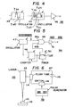
- the pulse generator 39 may be constructed in the form shown in Fig. 3.
- the pulse generator there shown includes two oscillators 40 and 41.
- the oscillator 40 produces a series of discrete, time- spaced narrow pulses a of an adjustable frequency f as well as a duration Iron and an interval ⁇ off which are adjustable independently of each other.
- the oscillator 41 produces a series of time-spaced wider pulses A of an adjustable frequency F as well as an on-time Ton and an off-time Toff which are adjustable independently of each other.
- the outputs of the oscillators 40 and 41 are combined by an AND gate 42 which thus issues through an amplifier 43 a series of successive, time-spaced group or trains A of discrete, time-spaced pulses a having controlled parameters ⁇ on, roff, Ton, Toff, n.
- the oscillators 40 and 41 may each be constituted by an astable multivibrator of conventional design.
- FIG. 4 An alternative form of the construction of the pulse generator 39 shown in Fig. 4 makes use of the series connection of two oscillators 44 and 45.
- the oscillator 44 operates at adjustable frequency f to provide switching pulses of adjustable duration ⁇ on and interval Toff which are applied via an amplifier 46 to the switch 22 (Fig. 2).
- the oscillator 45 operates at an adjustable frequency F which is lower than the frequency f of the oscillator 44 to provide control pulses of adjustable on-time Ton and off-time Toff which are applied to the oscillator 44. Accordingly, the switch 22 is operated to turn on and off the DC source 21 (Fig.
- the oscillators 44 may each be constituted by an astable multivibrator of conventional design.
- Fig. 5 shows another form of the pulse generator 39 which may be employed.
- an oscillator 47 e.g. an astable multivibrator, furnishes a uniform series of signal pulses a to an AND gate 48 through the latter's first input terminal 48a.
- the oscillator 47 has an additional output fed to a counter 49 which is adapted to count an adjustable preset number n of output pulses from the oscillator 47, which number determines the time duration Ton.
- the counter 49 upon the counting is reset while issuing a trigger signal which is applied to activate a timer 50, e.g. a monostable multivibrator, which determines an adjustable time Toff for groups or trains A1, A2, A3, ....
- the timer 50 when actuated, the timer 50 provides an "inhibit” signal to disable the AND gate 48 to pass, and to interrupt, the pulses a to an amplifier 51.
- the timer 50 upon termination of the time Toff, provides an "enable” signal to permit the AND gate 48 to pass to pulses a to the amplifier 51.
- Fig. 6 shows another embodiment of the present invention, viz. as applied to a laser system 110, e.g. for machining a workpiece 111 mounted on a worktable 112.
- a laser gun 113 is pumped or actuated by a flush tube 114 to produce a laser beam which is trained towards the workpiece 111.
- the flush tube 114 is energized by a DC supply 115 which is connected thereto in series with a power switch 116. The latter is turned on and off in response to signal pulses furnished by a pulse generator 39, which may be of any one of the constructions shown in Figs.
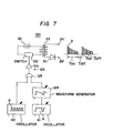
- Fig. 7 shows another embodiment of the power supply 20 for energizing a beam-gun system as previously described.
- the power supply 20 in this embodiment includes, as in the arrangement of Fig. 2, a step-up transformer 23 having output terminals 24' and 29' at its secondary side with a diode 30 being connected as shown.
- the primary winding of the transformer 23 is connected in series with a DC source 121 and a switch 122 which is designed to form a variable resistor which provides at the transformer 23 a voltage output whose magnitude is proportional to a control input signal applied thereto from a pulse generator 123.
- the pulse generator 123 here again includes two oscillators 40 and 41 as previously described, which provide a uniform series of narrow adjustable pulses a and a uniform succession of adjustable wider pulses A.
- a waveform generating circuit 124 adapted to provide a variable lump voltage waveform in response to the leading edge of each of the pulses produced in the oscillator 41, and also to respond to the trailing edge thereof to terminate the produced lump voltage.
- the outputs of the oscillator 40 and the waveform-generating circuit 124 are tied at a gate 125 whose output is fed via an amplifier 126 to the switch 122.
- there develops a series of composite pulses across the output terminals 24' and 29' of the power supply 120 each of the composite pulses having an envelop waveform determined by the circuit 124 and being composed of discrete, short-duration pulses a.
- the beam gun system can be energized by the developed series of these composite pulses to produce a corresponding series of pulsed energy beams for irradiation of a workpiece.
Landscapes
- Engineering & Computer Science (AREA)
- Mechanical Engineering (AREA)
- Welding Or Cutting Using Electron Beams (AREA)
Priority Applications (3)
| Application Number | Priority Date | Filing Date | Title |
|---|---|---|---|
| DE8383303165T DE3371754D1 (en) | 1983-06-01 | 1983-06-01 | Beamed energy radiation control method and apparatus, and processes and equipment comprising said method and apparatus respectively |
| EP83303165A EP0127706B1 (de) | 1983-06-01 | 1983-06-01 | Methode und Apparat zur Regelung einer gebündelten Strahlenergie sowie Verfahren und Einrichtung mit dieser Methode, bzw. diesem Apparat |
| DE1983303165 DE127706T1 (de) | 1983-06-01 | 1983-06-01 | Methode und apparat zur regelung einer gebuendelten strahlenergie sowie verfahren und einrichtung mit dieser methode, bzw. diesem apparat. |
Applications Claiming Priority (1)
| Application Number | Priority Date | Filing Date | Title |
|---|---|---|---|
| EP83303165A EP0127706B1 (de) | 1983-06-01 | 1983-06-01 | Methode und Apparat zur Regelung einer gebündelten Strahlenergie sowie Verfahren und Einrichtung mit dieser Methode, bzw. diesem Apparat |
Publications (2)
| Publication Number | Publication Date |
|---|---|
| EP0127706A1 true EP0127706A1 (de) | 1984-12-12 |
| EP0127706B1 EP0127706B1 (de) | 1987-05-27 |
Family
ID=8191176
Family Applications (1)
| Application Number | Title | Priority Date | Filing Date |
|---|---|---|---|
| EP83303165A Expired EP0127706B1 (de) | 1983-06-01 | 1983-06-01 | Methode und Apparat zur Regelung einer gebündelten Strahlenergie sowie Verfahren und Einrichtung mit dieser Methode, bzw. diesem Apparat |
Country Status (2)
| Country | Link |
|---|---|
| EP (1) | EP0127706B1 (de) |
| DE (2) | DE127706T1 (de) |
Citations (4)
| Publication number | Priority date | Publication date | Assignee | Title |
|---|---|---|---|---|
| DE2153695A1 (de) * | 1971-10-28 | 1973-05-10 | Steigerwald Strahltech | Verfahren und einrichtung zur regelung des strahlstroms bei technischen ladungstraegerstrahlgeraeten |
| DE2336223A1 (de) * | 1973-07-17 | 1975-02-06 | Adolf Dr Ing Schmitt | Verfahren zur informationsuebertragung mittels elektronenstrahlanlagen |
| DE2541943A1 (de) * | 1975-09-19 | 1977-03-24 | Siemens Ag | Elektronenstrahlgraviervorrichtung |
| US4219720A (en) * | 1978-07-06 | 1980-08-26 | Steigerwald Strahltechnik Gmbh | Energy beam welding with filler material |
Family Cites Families (3)
| Publication number | Priority date | Publication date | Assignee | Title |
|---|---|---|---|---|
| US4201905A (en) * | 1978-08-29 | 1980-05-06 | Houdaille Industries, Inc. | Laser cutting head attachment for punch presses |
| JPS56501818A (de) * | 1979-12-26 | 1981-12-10 | ||
| US4560856A (en) * | 1982-09-01 | 1985-12-24 | Westinghouse Electric Corp. | Pulsed laser machining apparatus |
-
1983
- 1983-06-01 EP EP83303165A patent/EP0127706B1/de not_active Expired
- 1983-06-01 DE DE1983303165 patent/DE127706T1/de active Pending
- 1983-06-01 DE DE8383303165T patent/DE3371754D1/de not_active Expired
Patent Citations (4)
| Publication number | Priority date | Publication date | Assignee | Title |
|---|---|---|---|---|
| DE2153695A1 (de) * | 1971-10-28 | 1973-05-10 | Steigerwald Strahltech | Verfahren und einrichtung zur regelung des strahlstroms bei technischen ladungstraegerstrahlgeraeten |
| DE2336223A1 (de) * | 1973-07-17 | 1975-02-06 | Adolf Dr Ing Schmitt | Verfahren zur informationsuebertragung mittels elektronenstrahlanlagen |
| DE2541943A1 (de) * | 1975-09-19 | 1977-03-24 | Siemens Ag | Elektronenstrahlgraviervorrichtung |
| US4219720A (en) * | 1978-07-06 | 1980-08-26 | Steigerwald Strahltechnik Gmbh | Energy beam welding with filler material |
Also Published As
| Publication number | Publication date |
|---|---|
| DE127706T1 (de) | 1987-05-21 |
| EP0127706B1 (de) | 1987-05-27 |
| DE3371754D1 (en) | 1987-07-02 |
Similar Documents
| Publication | Publication Date | Title |
|---|---|---|
| US4194106A (en) | Methods and devices for cutting, eroding, welding and depositing metallic and non-metallic materials by means of an electric arc | |
| US3214563A (en) | Electrical drilling | |
| JPH0459736B2 (de) | ||
| US3371190A (en) | Apparatus and method for perforating sheet plastic by means of an electron beam | |
| US4551606A (en) | Beamed energy radiation control method and apparatus | |
| WO1993006702A1 (en) | Plasma torch electronic circuit | |
| US3875366A (en) | Method and apparatus for regulating the beam current in industrial charge carrier beam apparatus | |
| EP0261914A2 (de) | Verfahren und Vorrichtung zur Erzeugung eines Lichtbogens | |
| US4393295A (en) | Apparatus and method for engraving with an electron beam | |
| GB1274876A (en) | Plasma arc heating apparatus | |
| CA1065022A (en) | Method and device for controlling an electric arc by rotating magnetic field | |
| JPS596024B2 (ja) | イオン源用電源装置 | |
| US3278796A (en) | Magnetically controllable plasma flame generator | |
| EP0075282B1 (de) | Gas-Laservorrichtung | |
| EP0127706B1 (de) | Methode und Apparat zur Regelung einer gebündelten Strahlenergie sowie Verfahren und Einrichtung mit dieser Methode, bzw. diesem Apparat | |
| US3679930A (en) | Method for increasing the output of an electron accelerator | |
| GB1523297A (en) | Charged particle beam apparatus | |
| JPH0751941A (ja) | レーザ放電誘導式放電加工装置 | |
| US4019091A (en) | Gas discharge electron gun for generating an electron beam by means of a glow discharge | |
| GB1183751A (en) | Charged Particle Generator with Electromagnetic Current Control. | |
| JP2621369B2 (ja) | 電子ビーム加工装置 | |
| JPS6156825A (ja) | 放電加工方法および装置 | |
| JPH0447422B2 (de) | ||
| US5097178A (en) | RF electron gun with cathode activating device | |
| JPS6338875B2 (de) |
Legal Events
| Date | Code | Title | Description |
|---|---|---|---|
| PUAI | Public reference made under article 153(3) epc to a published international application that has entered the european phase |
Free format text: ORIGINAL CODE: 0009012 |
|
| AK | Designated contracting states |
Designated state(s): DE FR GB IT |
|
| 17P | Request for examination filed |
Effective date: 19841129 |
|
| ITCL | It: translation for ep claims filed |
Representative=s name: FIAMMENGHI FIAMMENGHI RACHELI |
|
| EL | Fr: translation of claims filed | ||
| 17Q | First examination report despatched |
Effective date: 19860213 |
|
| ITF | It: translation for a ep patent filed | ||
| GRAA | (expected) grant |
Free format text: ORIGINAL CODE: 0009210 |
|
| DET | De: translation of patent claims | ||
| AK | Designated contracting states |
Kind code of ref document: B1 Designated state(s): DE FR GB IT |
|
| REF | Corresponds to: |
Ref document number: 3371754 Country of ref document: DE Date of ref document: 19870702 |
|
| ET | Fr: translation filed | ||
| PLBE | No opposition filed within time limit |
Free format text: ORIGINAL CODE: 0009261 |
|
| STAA | Information on the status of an ep patent application or granted ep patent |
Free format text: STATUS: NO OPPOSITION FILED WITHIN TIME LIMIT |
|
| 26N | No opposition filed | ||
| PGFP | Annual fee paid to national office [announced via postgrant information from national office to epo] |
Ref country code: GB Payment date: 19890430 Year of fee payment: 7 |
|
| PGFP | Annual fee paid to national office [announced via postgrant information from national office to epo] |
Ref country code: FR Payment date: 19890609 Year of fee payment: 7 |
|
| PGFP | Annual fee paid to national office [announced via postgrant information from national office to epo] |
Ref country code: DE Payment date: 19890726 Year of fee payment: 7 |
|
| PG25 | Lapsed in a contracting state [announced via postgrant information from national office to epo] |
Ref country code: GB Effective date: 19900601 |
|
| GBPC | Gb: european patent ceased through non-payment of renewal fee | ||
| PG25 | Lapsed in a contracting state [announced via postgrant information from national office to epo] |
Ref country code: FR Effective date: 19910228 |
|
| PG25 | Lapsed in a contracting state [announced via postgrant information from national office to epo] |
Ref country code: DE Effective date: 19910301 |
|
| REG | Reference to a national code |
Ref country code: FR Ref legal event code: ST |