EP0127995A2 - Schmiersprühvorrichtung für Glasmatrize - Google Patents
Schmiersprühvorrichtung für Glasmatrize Download PDFInfo
- Publication number
- EP0127995A2 EP0127995A2 EP84303600A EP84303600A EP0127995A2 EP 0127995 A2 EP0127995 A2 EP 0127995A2 EP 84303600 A EP84303600 A EP 84303600A EP 84303600 A EP84303600 A EP 84303600A EP 0127995 A2 EP0127995 A2 EP 0127995A2
- Authority
- EP
- European Patent Office
- Prior art keywords
- lubricant
- air
- moulds
- spray
- discharge opening
- Prior art date
- Legal status (The legal status is an assumption and is not a legal conclusion. Google has not performed a legal analysis and makes no representation as to the accuracy of the status listed.)
- Granted
Links
Images


Classifications
-
- C—CHEMISTRY; METALLURGY
- C03—GLASS; MINERAL OR SLAG WOOL
- C03B—MANUFACTURE, SHAPING, OR SUPPLEMENTARY PROCESSES
- C03B40/00—Preventing adhesion between glass and glass or between glass and the means used to shape it, hold it or support it
- C03B40/02—Preventing adhesion between glass and glass or between glass and the means used to shape it, hold it or support it by lubrication; Use of materials as release or lubricating compositions
- C03B40/027—Apparatus for applying lubricants to glass shaping moulds or tools
Definitions
- This invention relates to the manufacture of glass bottles or other hollow glassware.
- the invention is concerned with the application of lubricant to the moulds in which parisons are made.
- the object of the present invention is to provide a spray device able to spray down relatively deep blank moulds.
- a lubricant spray device for spraying lubricant onto a blank mould of a hollow glassware moulding machine containing a passage for pressurised air leading to pressurised air discharge, opening, and having a lubricant passage leading to a lubricant discharge opening, characterised in that the pressurised air discharge opening is arranged such that the discharging pressurised air entrains additional air from the surrounding atmosphere, and the lubricant discharge opening is positioned to discharge the lubricant into the flow of entrained air.
- a suitable arrangement for entraining the surrounding atmospheric air is to discharge the pressurised air through a narrow orifice shaped and arranged so that the discharging air follows an extension of the wall at one side of the orifice. As it does so, it entrains surrounding air in accordance with the Coanda principle.
- the spray delivery device defines a through passage for the entrained air, and the lubricant discharge opening is positioned to discharge into this passage.
- the lubricant discharge opening is positioned to discharge into this passage.
- it is a continuous slot encircling this passage.
- the volume of entrained air may typically be in excess of ten, and indeed twenty times the volume of pressurised air.
- the invention also embraces a machine for moulding parisons for hollow glassware fitted with one or more spray devices as defined above.
- the machine may be provided with e.g. connected to, means for periodically discharging lubricant and pressurised air through the device(s) onto the blank moulds of the machine.
- the machine may be a so-called IS (Independent Section) machine having the devices fitted in or incorporated into movable carrier(s) arranged to position the device(s) over the closed positions of respective mould cavities.
- These carriers may be the funnel arms of the machine.
- this invention provides a method of moulding parisons for hollow glasswares in which lubricant is periodically sprayed onto the blank moulds by means of one or more spray devices as set forth above.
- the spray devices of this invention could be used in various ways. One possibility is for them to be incorporated in fixed mountings to spray the moulds while open, in accordance with our EP-A-43261. However, the spray is preferably applied to the closed moulds, (or possibly to nearly closed, closing moulds) and it will then generally lubricate the neck rings below the moulds, as well as the mould cavities themselves.
- the spray devices For spraying into closed moulds, as is preferred, one possibility is for the spray devices to be carried in the funnel arms of an IS machine. The gobs of molten glass will then almost certainly need to be loaded directly into the mould cavities, so-called “direct loading”, rather than loaded through the funnel.
- a "press and blow” process could be employed. When this is combined with direct loading the funnel arm is not needed, and hence is available for carrying the spray devices of this invention.
- a modified "blow and blow” process could be employed, and this is a further inventive feature.
- this modified blow and blow process the "settle air" which presses the gob down in the mould cavity is delivered through a spray delivery device of this invention.
- the moulding cycle then comprises the steps of:
- the spray device can be carried in a funnel arm, and the settle air can be delivered through a normal baffle.
- the spray device Periodically, the spray device is positioned over the closed moulds while the mould cavity is empty, and lubricant is discharged into the cavity between the closed or closing moulds.
- each spray device is carried by a movable carrier structure which is an additional part fitted to the glass moulding machine.
- This carrier structure remains in an inoperative position except when required to effect lubrication. It then moves to an operative position to spray into the closed moulds.
- Lubrication will generally take place at regular intervals, after a predetermined number of moulding cycles have occurred. With all the above possibilities for spraying into closed (or closing) moulds, the lubrication preferably takes place during a cycle in which no gob is loaded. Alternatively, however, the timing of all the moulding cycles may be adjusted to create an interval before the gob enters the closed moulds. Lubrication might then be carried out during this interval in required cycles only, immediately before entry of a gob.
- the spray head 1 shown consists of three parts; an upper ring 2, a lower ring 4 and an insert 6 within the lower ring.
- the three parts are fastened together by bolts, not shown, passing through the upper ring 2 downwardly into tapped holes in the lower ring 4 and further bolts, also not shown, passing downwardly through the lower ring 4 into further tapped holes in the insert 6.
- the spray head defines a central passage 7 for entrained air.
- the upper ring 2 is provided with a port 8 for the admission of lubricant, which may be a graphite- in-oil suspension.
- This port communicates by bores 10, 12 with a passage 14 in a plug 16 inserted into the ring 2 and retained by a small screw 17.
- the passage 14 leads to a discharge aperture 18 approximately at the centre of the passageway 7.
- the insert 6 has a base portion 22 with an upstanding cylindrical portion 24 which is dimensioned to be spaced from the ring 4 and hence defines a cylindrical chamber 26 between the portion 24 and the ring 4.
- the upper end of the portion 24 has a bulbous curved shape and is dimensioned so that a narrow aperture 28 is defined between it and the upper ring 2.
- the upper ring 2 is provided with a port 30 for the admission of compressed air. This communicates (through drilled holes 32, 34, 36) with the cylindrical chamber 26.
- the insert's inner wall 27 is of lesser diameter than the adjacent wall 29 of the central hole through the upper ring 2, and the insert provides a curved wall portion 38 leading from the aperture 28 to the wall 27.
- the spray head is connected to equipment as described in our European Patent Application EP-A-43261.
- This equipment will, when required, supply pressurised air through a flexible hose to the port 30 while also supplying the liquid lubricant through another hose to the port 8.
- the compressed air causes the flow of entrained air down through the passageway 7 in the manner just described and while this is taking place lubricant is discharged through the hole 18 into the flow of entrained air which atomises the lubricant so that it is carried downwardly as a spray of lubricant in the air stream.
- the equipment shown in our EP-A-43261 counts IS machine cycles, and effects lubrication each time a preset count is reached. It usually lubricates every section of an IS machine in succession. It also permits additional applications of lubricant under manual command to any one section.
- the spray head 1 is dimensioned to fit into one of the apertures provided in the funnel arm 50 of an IS machine.
- This arm 50 is used to carry the spray head into place above a pair of closed-together blank moulds, either to spray lubricant or for settle air to be blown through the spray head from a baffle of the IS machine.
- the funnel arm and baffle arm move between their usual positions.
- the spray head 1 is provided with an upper central space 52 in which the baffle 54 can be received as shown.
- the baffle 54 incorporates passageways 55 for settle air, as is conventional.
- the spray head is provided with a chamfer 56 enabling it to rest sealingly in the top of a pair of closed together blank moulds 58 (but if these had a different shape, the lower edge of the spray head would be shaped to fit).
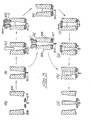
- Fig. 3 shows the spray head 1 employed in a blow-and-blow process for which lubrication is carried out after a predetermined number of moulding cycles. No gob is loaded during a lubrication cycle.
- the sequence of operations shown in Fig. 3 is as follows:
- lubrication is effected automatically in the next cycle which is modified.
- stage (b) no gob is loaded.
- the funnel arm then carries the head 1 onto the top of the moulds 58 and lubricant is sprayed (stage k).
- the baffle 54 does not go onto the moulds at all, and after the lubricant has been sprayed the moulds remain empty until the next cycle.
- the plunger is preferably kept down while lubricant is sprayed, to ensure an air outlet opening at the bottom of the mould cavity.
- the spray head 1 can be put on and taken off at the same points in the cycle as for the blowing in of settle air, but the baffle and plunger need not move at all during the cycle.
- the counting of moulding cycles and the discharge of pressurised air and lubricant are effected with equipment according to our EP-A-43261 mentioned above. Signals from this equipment can be employed to disable appropriate valves of the IS machine during a lubrication cycle, so as to prevent entry of a gob, and prevent unwanted movements of plunger 60 and baffle 54.
- movements which are not required during a lubrication cycle are prevented by disabling IS machine valves during the appropriate part of a lubrication cycle. Movements which are only required during a lubrication cycle can be achieved by disabling the appropriate valves in normal moulding cycles.
- the valve supplying pressure to the funnel arm would be disabled during normal moulding cycles of a direct loading press-and-blow process, but the funnel arm would be used to put the spray head on the moulds during a lubrication cycle.
- Figures 4 to 8 show a further form of spray device.
- This is for spraying the mould cavities of a double gob machine (i.e. a machine having two mould cavities in each pair of blank moulds).
- the device has a cast block 70 which is part of a carrier structure fitted as an additional part to an IS machine.
- This block has a pair of inserts 72 which are a push fit into bores in the block 70.
- O-rings 74 seal between the inserts 72 and the block 70.
- the inserts 72 provide the discharge openings for pressurised air.
- the lubricant discharge openings are formed in a plate 76 which is mounted on the block 70 so as to project above the inserts 72.
- Each insert 72 consists of an upper part 80 and a lower part 82 secured to the upper part by three screws 84. Both parts are annular, defining a through central passage 87. They are formed by turning on a lathe. The upper surface of the lower part 82 is cut away to form two annular chambers 88,90 for pressurised air, separated by an annular collar 92 with a flat top surface. The screws 84 pass vertically through this collar 92 while a number of horizontal bores 94 distributed around the collar 92 provide communication between the annular chambers 88 and 90.
- An annular shim 96 is provided between the collar 92 and the flat under surface of the upper part 80. Because of this shim, a narrow opening having a vertical width equal to the thickness of the shim, is provided at 98 encircling the through passage 87. This is the discharge opening for pressurised air. (The thickness of the shim is shown somewhat exaggerated in the drawings). Pressurised air is introduced into the block 70 through a port not shown and travels via air passages 100, 102 in the block 70 to the annular chamber 88, thence via the horizontal bores 94 to the chamber 90 from which the pressurised air discharges through the narrow opening 98. The upper surface of the lower part 82 extends beyond the opening 98 and merges smoothly into the through bore 87. The discharging pressurised air follows around this smooth surface into the through bore 87 and as it does so it entrains air from the surrounding atmosphere to be ejected downwardly through the bore 87.
- the plate 76 is fast with a small central block 106 which rests on the block 70 and hence spaces the plate 76 above the block 70.
- the plate 76 and block 106 are releasably secured on to the block 70 by means of a screw 108. This allows the plate 76 to be taken off either for cleaning or to allow the inserts 72 to be removed.
- Lubricant enters the block 70 through a port, not shown, and then travels via bores 112, 114, 116 and 118 to lubricant discharge openings 120 in the undersurface of the plate 76 directly above the through passages 87.
- a sealing ring is provided at 122 and the block 106 may be provided with dowels to engage into the cast block 70 to ensure proper alignment.
- this spray device is also connected to equipment as described in our European Patent Application EP-A 43261.
- This equipment will count machine cycles, as mentioned above, and when required supply pressurised air and lubricant through flexible hoses to the respective ports (not shown) in the cast block 70.
- the discharge of lubricant from the openings 120 takes place while pressurised air is being discharged through the narrow openings 98.
- the equipment can also control movement of the carrier structure which incorporates the cast block 70.
- the lubricant passages could possibly incorporate a captive ball to prevent lubricant being shaken out when not being discharged under pressure.
- a captive ball could be fitted in the passage 14 in the plug 16 of Fig. 1, or in the rising passage 118 in the plate 76.
- the inserts' screws 84 are shown as inserted upwardly, but it would be equally possible to insert them through the upper parts 80 into tapped holes in the lower parts 82, which could be through holes.
Landscapes
- Chemical & Material Sciences (AREA)
- Engineering & Computer Science (AREA)
- Materials Engineering (AREA)
- Organic Chemistry (AREA)
- Nozzles (AREA)
- Re-Forming, After-Treatment, Cutting And Transporting Of Glass Products (AREA)
Applications Claiming Priority (2)
| Application Number | Priority Date | Filing Date | Title |
|---|---|---|---|
| GB838315153A GB8315153D0 (en) | 1983-06-02 | 1983-06-02 | Moulding |
| GB8315153 | 1983-06-02 |
Publications (3)
| Publication Number | Publication Date |
|---|---|
| EP0127995A2 true EP0127995A2 (de) | 1984-12-12 |
| EP0127995A3 EP0127995A3 (en) | 1986-01-02 |
| EP0127995B1 EP0127995B1 (de) | 1988-07-27 |
Family
ID=10543694
Family Applications (1)
| Application Number | Title | Priority Date | Filing Date |
|---|---|---|---|
| EP84303600A Expired EP0127995B1 (de) | 1983-06-02 | 1984-05-29 | Schmiersprühvorrichtung für Glasmatrize |
Country Status (5)
| Country | Link |
|---|---|
| US (1) | US4861363A (de) |
| EP (1) | EP0127995B1 (de) |
| DE (1) | DE3472943D1 (de) |
| ES (1) | ES8504090A1 (de) |
| GB (1) | GB8315153D0 (de) |
Families Citing this family (5)
| Publication number | Priority date | Publication date | Assignee | Title |
|---|---|---|---|---|
| US6902708B1 (en) * | 2000-04-25 | 2005-06-07 | Air Liquide America Corporation | Method and apparatus for making carbon black |
| US7383694B2 (en) * | 2005-02-15 | 2008-06-10 | Owens-Brockway Glass Container Inc. | Lubrication assembly for glassware forming molds |
| ITTO20080234A1 (it) * | 2008-03-27 | 2009-09-28 | Bottero Spa | Metodo e macchina per la realizzazione di articoli di vetro |
| ES2969576T3 (es) * | 2021-08-05 | 2024-05-21 | Emhart Glass Sa | Máquina de formación de vidrio que comprende un dispositivo y método de limpieza |
| EP4365143A1 (de) | 2022-11-04 | 2024-05-08 | Emhart Glass S.A. | Glasformanlage und verfahren zum betreiben derselben |
Family Cites Families (14)
| Publication number | Priority date | Publication date | Assignee | Title |
|---|---|---|---|---|
| US3141752A (en) * | 1960-05-03 | 1964-07-21 | Owens Illinois Glass Co | Lubrication of glass molds |
| US3480422A (en) * | 1966-12-23 | 1969-11-25 | Armstrong Cork Co | Lubrication system for a parison blank |
| US3536468A (en) * | 1967-12-14 | 1970-10-27 | Owens Illinois Inc | Glass parison forming with settle blow closing means |
| US3623856A (en) * | 1970-02-02 | 1971-11-30 | Owens Illinois Inc | Mold spray apparatus |
| US3672860A (en) * | 1970-08-19 | 1972-06-27 | Owens Illinois Inc | Glass gob shaping and delivering means |
| DE2141455C3 (de) * | 1971-08-18 | 1975-12-04 | Deutsche Acheson Gmbh, 7900 Ulm | Einrichtung zum Einbringen von versprühbarem Schmiermittel in Formen für die Herstellung von Hohlglaskörpern |
| US3814594A (en) * | 1972-11-17 | 1974-06-04 | Owens Illinois Inc | Blank mold spray |
| US3857691A (en) * | 1973-10-09 | 1974-12-31 | Maul Bros Inc | Gob distributor |
| US4206160A (en) * | 1978-09-25 | 1980-06-03 | The United States Of America As Represented By The Department Of Health, Education And Welfare | Mechanical device to produce a finely dispersed aerosol |
| US4396529A (en) * | 1978-11-13 | 1983-08-02 | Nordson Corporation | Method and apparatus for producing a foam from a viscous liquid |
| EP0043261A1 (de) * | 1980-06-26 | 1982-01-06 | Graphoidal Developments Limited | Glasformschmierung |
| US4284590A (en) * | 1980-09-17 | 1981-08-18 | Respiratory Care, Inc. | Multiple aspirator for nebulizer |
| US4452578A (en) * | 1981-08-27 | 1984-06-05 | Acheson Industries, Inc. | Spray apparatus for metal forming and glassware forming machines |
| US4422574A (en) * | 1982-01-25 | 1983-12-27 | Par-Way Manufacturing Co. | Spray enrober nozzle construction with removable and interchangeable components |
-
1983
- 1983-06-02 GB GB838315153A patent/GB8315153D0/en active Pending
-
1984
- 1984-05-29 EP EP84303600A patent/EP0127995B1/de not_active Expired
- 1984-05-29 DE DE8484303600T patent/DE3472943D1/de not_active Expired
- 1984-06-01 ES ES533364A patent/ES8504090A1/es not_active Expired
-
1987
- 1987-11-30 US US07/126,492 patent/US4861363A/en not_active Expired - Fee Related
Also Published As
| Publication number | Publication date |
|---|---|
| EP0127995A3 (en) | 1986-01-02 |
| ES533364A0 (es) | 1985-04-01 |
| US4861363A (en) | 1989-08-29 |
| GB8315153D0 (en) | 1983-07-06 |
| ES8504090A1 (es) | 1985-04-01 |
| DE3472943D1 (en) | 1988-09-01 |
| EP0127995B1 (de) | 1988-07-27 |
Similar Documents
| Publication | Publication Date | Title |
|---|---|---|
| US4409010A (en) | Method and apparatus for glass mould lubrication | |
| US3141752A (en) | Lubrication of glass molds | |
| EP0278114B1 (de) | Vorrichtung und Verfahren zum Schmieren einer Matrize für Glasgegenstände | |
| US3523016A (en) | Mold lubricating means for glassware making machines | |
| EP0127995B1 (de) | Schmiersprühvorrichtung für Glasmatrize | |
| EP0110695B1 (de) | Blaskopf für eine Hohlglasherstellungsmaschine | |
| US4502879A (en) | Mould cooling arrangement for a glassware forming machine | |
| US3801299A (en) | Apparatus for producing hollow glass objects | |
| US3480422A (en) | Lubrication system for a parison blank | |
| US4604120A (en) | Method and apparatus for lubricating and moulding glass parisons | |
| CA2116273C (en) | Mold cooling apparatus for a glassware forming machine | |
| US4867777A (en) | Apparatus and method for lubricating glassware mold | |
| EP0147229B1 (de) | Vorrichtung zum Schmieren von Matrizen für Maschinen zum Herstellen von Glasgegenständen | |
| US4470836A (en) | Parison mold and baffle system for an automatic molding machine | |
| CA1212234A (en) | Method of cooling a mould | |
| JPS623027A (ja) | ガラス製びん機の金型潤滑液塗布装置 | |
| JP4372949B2 (ja) | I.s.機械の真空圧機構 | |
| JPH0630816Y2 (ja) | ガラス壜用成形金型の潤滑液塗布装置 | |
| AU2005275025B2 (en) | Neck ring cooling | |
| GB2132188A (en) | Spray system for glass moulds | |
| JPS62279044A (ja) | 鍛造金型の潤滑、冷却装置 | |
| EP0114480A1 (de) | Sprühsystem | |
| EP0121346A1 (de) | Kühlen von Blasformen | |
| WO1984003495A1 (en) | Improved blowhead apparatus | |
| KR20000042994A (ko) | 유리제품압축성형장치용 냉각장치 |
Legal Events
| Date | Code | Title | Description |
|---|---|---|---|
| PUAI | Public reference made under article 153(3) epc to a published international application that has entered the european phase |
Free format text: ORIGINAL CODE: 0009012 |
|
| AK | Designated contracting states |
Designated state(s): DE FR GB IT SE |
|
| PUAL | Search report despatched |
Free format text: ORIGINAL CODE: 0009013 |
|
| AK | Designated contracting states |
Designated state(s): DE FR GB IT SE |
|
| 17P | Request for examination filed |
Effective date: 19860512 |
|
| 17Q | First examination report despatched |
Effective date: 19870312 |
|
| GRAA | (expected) grant |
Free format text: ORIGINAL CODE: 0009210 |
|
| AK | Designated contracting states |
Kind code of ref document: B1 Designated state(s): DE FR GB IT SE |
|
| REF | Corresponds to: |
Ref document number: 3472943 Country of ref document: DE Date of ref document: 19880901 |
|
| ET | Fr: translation filed | ||
| ITF | It: translation for a ep patent filed | ||
| PLBE | No opposition filed within time limit |
Free format text: ORIGINAL CODE: 0009261 |
|
| STAA | Information on the status of an ep patent application or granted ep patent |
Free format text: STATUS: NO OPPOSITION FILED WITHIN TIME LIMIT |
|
| 26N | No opposition filed | ||
| ITTA | It: last paid annual fee | ||
| EAL | Se: european patent in force in sweden |
Ref document number: 84303600.5 |
|
| PGFP | Annual fee paid to national office [announced via postgrant information from national office to epo] |
Ref country code: FR Payment date: 19960516 Year of fee payment: 13 |
|
| PGFP | Annual fee paid to national office [announced via postgrant information from national office to epo] |
Ref country code: GB Payment date: 19960517 Year of fee payment: 13 |
|
| PGFP | Annual fee paid to national office [announced via postgrant information from national office to epo] |
Ref country code: SE Payment date: 19960521 Year of fee payment: 13 Ref country code: DE Payment date: 19960521 Year of fee payment: 13 |
|
| PG25 | Lapsed in a contracting state [announced via postgrant information from national office to epo] |
Ref country code: GB Effective date: 19970529 |
|
| PG25 | Lapsed in a contracting state [announced via postgrant information from national office to epo] |
Ref country code: SE Effective date: 19970530 |
|
| GBPC | Gb: european patent ceased through non-payment of renewal fee |
Effective date: 19970529 |
|
| PG25 | Lapsed in a contracting state [announced via postgrant information from national office to epo] |
Ref country code: FR Free format text: LAPSE BECAUSE OF NON-PAYMENT OF DUE FEES Effective date: 19980130 |
|
| EUG | Se: european patent has lapsed |
Ref document number: 84303600.5 |
|
| PG25 | Lapsed in a contracting state [announced via postgrant information from national office to epo] |
Ref country code: DE Free format text: LAPSE BECAUSE OF NON-PAYMENT OF DUE FEES Effective date: 19980203 |
|
| REG | Reference to a national code |
Ref country code: FR Ref legal event code: ST |