EP0129038A1 - Dispositif de palier pour fonctionnement sous l'eau ou en milieux boueux - Google Patents
Dispositif de palier pour fonctionnement sous l'eau ou en milieux boueux Download PDFInfo
- Publication number
- EP0129038A1 EP0129038A1 EP84105161A EP84105161A EP0129038A1 EP 0129038 A1 EP0129038 A1 EP 0129038A1 EP 84105161 A EP84105161 A EP 84105161A EP 84105161 A EP84105161 A EP 84105161A EP 0129038 A1 EP0129038 A1 EP 0129038A1
- Authority
- EP
- European Patent Office
- Prior art keywords
- bearing
- gap
- axis
- arrangement according
- gaps
- Prior art date
- Legal status (The legal status is an assumption and is not a legal conclusion. Google has not performed a legal analysis and makes no representation as to the accuracy of the status listed.)
- Granted
Links
Images

Classifications
-
- F—MECHANICAL ENGINEERING; LIGHTING; HEATING; WEAPONS; BLASTING
- F16—ENGINEERING ELEMENTS AND UNITS; GENERAL MEASURES FOR PRODUCING AND MAINTAINING EFFECTIVE FUNCTIONING OF MACHINES OR INSTALLATIONS; THERMAL INSULATION IN GENERAL
- F16C—SHAFTS; FLEXIBLE SHAFTS; ELEMENTS OR CRANKSHAFT MECHANISMS; ROTARY BODIES OTHER THAN GEARING ELEMENTS; BEARINGS
- F16C33/00—Parts of bearings; Special methods for making bearings or parts thereof
- F16C33/72—Sealings
- F16C33/74—Sealings of sliding-contact bearings
-
- F—MECHANICAL ENGINEERING; LIGHTING; HEATING; WEAPONS; BLASTING
- F16—ENGINEERING ELEMENTS AND UNITS; GENERAL MEASURES FOR PRODUCING AND MAINTAINING EFFECTIVE FUNCTIONING OF MACHINES OR INSTALLATIONS; THERMAL INSULATION IN GENERAL
- F16C—SHAFTS; FLEXIBLE SHAFTS; ELEMENTS OR CRANKSHAFT MECHANISMS; ROTARY BODIES OTHER THAN GEARING ELEMENTS; BEARINGS
- F16C17/00—Sliding-contact bearings for exclusively rotary movement
- F16C17/12—Sliding-contact bearings for exclusively rotary movement characterised by features not related to the direction of the load
- F16C17/14—Sliding-contact bearings for exclusively rotary movement characterised by features not related to the direction of the load specially adapted for operating in water
-
- F—MECHANICAL ENGINEERING; LIGHTING; HEATING; WEAPONS; BLASTING
- F16—ENGINEERING ELEMENTS AND UNITS; GENERAL MEASURES FOR PRODUCING AND MAINTAINING EFFECTIVE FUNCTIONING OF MACHINES OR INSTALLATIONS; THERMAL INSULATION IN GENERAL
- F16C—SHAFTS; FLEXIBLE SHAFTS; ELEMENTS OR CRANKSHAFT MECHANISMS; ROTARY BODIES OTHER THAN GEARING ELEMENTS; BEARINGS
- F16C33/00—Parts of bearings; Special methods for making bearings or parts thereof
- F16C33/72—Sealings
- F16C33/76—Sealings of ball or roller bearings
-
- Y—GENERAL TAGGING OF NEW TECHNOLOGICAL DEVELOPMENTS; GENERAL TAGGING OF CROSS-SECTIONAL TECHNOLOGIES SPANNING OVER SEVERAL SECTIONS OF THE IPC; TECHNICAL SUBJECTS COVERED BY FORMER USPC CROSS-REFERENCE ART COLLECTIONS [XRACs] AND DIGESTS
- Y10—TECHNICAL SUBJECTS COVERED BY FORMER USPC
- Y10S—TECHNICAL SUBJECTS COVERED BY FORMER USPC CROSS-REFERENCE ART COLLECTIONS [XRACs] AND DIGESTS
- Y10S277/00—Seal for a joint or juncture
- Y10S277/91—O-ring seal
-
- Y—GENERAL TAGGING OF NEW TECHNOLOGICAL DEVELOPMENTS; GENERAL TAGGING OF CROSS-SECTIONAL TECHNOLOGIES SPANNING OVER SEVERAL SECTIONS OF THE IPC; TECHNICAL SUBJECTS COVERED BY FORMER USPC CROSS-REFERENCE ART COLLECTIONS [XRACs] AND DIGESTS
- Y10—TECHNICAL SUBJECTS COVERED BY FORMER USPC
- Y10S—TECHNICAL SUBJECTS COVERED BY FORMER USPC CROSS-REFERENCE ART COLLECTIONS [XRACs] AND DIGESTS
- Y10S277/00—Seal for a joint or juncture
- Y10S277/911—Seal combined with nominal motion transmitting device
Definitions
- the invention relates to a bearing arrangement with an outer bearing housing and at least one inner bearing element for storing a component and with gaps open to the outside and to the outside and at an acute angle to the bearing axis.
- a seal is arranged in the form of a circumferential sealing washer, which covers an annular gap between an inner ring of the rolling bearing and the rolling bearing.
- the sealing washer should follow with its axial distance from the rolling bearing to the outside area a conical surface, which is opposite a corresponding counter-conical surface of a counter-body at a short distance, however, the annular gap then runs in a radial plane and ends in a cylindrical part.
- So-called labyrinth seals, oil chamber seals and the like are also known, in order to seal a gap between parts which are attached to one another against the entry of a surrounding medium.
- the sealing surfaces are perpendicular to the shaft axis.
- Slide or roller bearings such as roller and ball bearings and other bearings are included as at least one inner bearing element.
- Such bearing elements are under the specified operating conditions under considerable loads, the effort of the known designs having been operated with extremely complicated seals.
- a preferred embodiment When speaking of a shaft, a preferred embodiment provides a horizontally arranged shaft in a machine. A bearing element is arranged on the shaft, on which a movable component is mounted. A quasi stationary bearing for the rotating shaft is also included.
- the mentioned bearing element can be designed as an eccentric disk-like drive element, and the component is provided as a part that can be moved on this drive element. It is known that at least one bearing bush is arranged on the bearing or drive element between the parts brought together.
- the invention has for its object to improve a bearing arrangement of the type specified in such a way that the entry of contaminants is largely prevented even when operating under unfavorable influences with simple means.
- the centrifugal force of the one wall part exerts forces on the gap which is directed obliquely to the shaft axis during the circulation, which eject heavier particles in the water from the gaps.
- particles that are thrown off are given a direction by reflection when they strike the gap wall opposite the circulating part or drive parts, which direction therefore runs towards the gap opening in the sense of expulsion.
- the at least one sealing ring at a distance from the outer end forms a catchment ground for the material to be flung off, this sealing at least one sealing ring closing the gap which runs obliquely to the shaft axis.
- the lubrication provides an additional sealing medium, which in particular also ensures operability when the machine is at a standstill.
- a conically directed gap is followed by a gap section running parallel to the bearing axis next to the bearing element, and at least one sealing ring is also arranged in this gap section. Lubrication of the gap between the two sealing rings is preferred. As a result, this additional sealing medium is limited to a gap section.
- the retaining rings are particularly advantageously designed with lubrication channels for gap lubrication.
- a bearing element designed as a bearing bush is framed by two L-shaped bearing bushes, the legs of which run parallel to the bearing axis form wall sections of correspondingly running gap sections. This contributes to a simple execution.
- a gap width of the order of 1 mm is preferred. This measure has also proven to be advantageous when cleaning the sewer. The result of this is that larger particles cannot penetrate anyway, but particles of smaller diameter are thrown off under the resulting centrifugal force.
- Such an embodiment is advantageous for vertically or horizontally arranged shafts.
- a bearing element is arranged on these, on which a movable component is mounted.
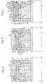
- the shaft 1 is driven in a manner not shown.
- Fig. 1 shows a bearing 2 for this shaft.
- This bearing is supported on a support 3.
- a bearing housing 4 is arranged, which can consist of 2 half shells, which are clamped together in the usual way.
- This support contains bearing shells 5, 6, in which a bearing bush 7 runs, which is arranged on the shaft 1.
- cover disks 8, 9 are arranged on the shaft in a rotationally fixed manner, the outer edges 10, 11 of which are directed at an acute angle to the axis of the shaft 1, specifically to the shaft 1 in the sections which are directed away from the bearing bush 7.
- retaining rings 12, 13 are fastened, which have a wall section 14, 15 which runs parallel to the outer edges 10, 11, so that gaps 16, 17 are formed which are inclined to the outside are oriented away from the bearing bush 7.
- FIG. 1 shows a particularly simple embodiment of a shaft bearing.
- Other elements such as sealing rings, can also be arranged on it, as described in the following figures.
- FIGS. 2-4 show a preferred embodiment in which an eccentric disk-like drive element 18 is arranged on the shaft 1 in a rotationally fixed manner. This is carried out in the outer circumference with shoulders 19, 20, between which the actual bearing surface 21 of the eccentric disc is arranged.
- a bearing bush 7 is located on this bearing surface. It goes without saying that, instead of such a bearing bush, another bearing means, such as elements of a rolling bearing, can be arranged.
- the cover disks 8, 9 are fastened in a rotationally fixed manner to the drive element, for example by screwing 22, 23.
- Their edges 10, 11 facing away from the shaft run at an angle of 45 ° to the axis of the shaft 1.
- a component 24 driven by the eccentric disk Arranged on the bearing bush 7 or corresponding bearing elements is a component 24 driven by the eccentric disk, which is only partially shown and forms at least one ring which surrounds the eccentric disk and is moved back and forth when the eccentric disk rotates.
- Retaining rings 27, 28, which correspond to the retaining rings 12, 13 in FIG. 1, are fastened to this component by screwing 25, 26 or corresponding fastening means.
- the retaining rings 27, 28 are with regard to the bearings Bush 7 or corresponding bearing means dimensioned so that wall sections 15, 16 extending obliquely to the shaft 1 run parallel to the edges 10, 11 in a section of about 1 mm.
- the retaining rings 27, 28 also have wall sections 29, 30 which run parallel to the shaft 1 and form a corresponding shaft-parallel gap on the shoulders 19, 20.
- a gap section 31 is formed at an angle to the axis of the shaft 1 and a gap section 32 parallel to the shaft of the axis 1.
- Sealing rings 33, 34 are arranged in both gap sections 31, 32 and are received in chambers 35, 36 which are formed in the holding rings 27, 28.
- two further bearing bushes 37, 38 with an L-shaped cross section are provided, which surround the bearing bush 7 and limit the shaft-parallel gap sections 31, 32 with their shaft-parallel legs 39, 40.
- chambers 41, 42 for the sealing rings 34 are arranged in these legs, which pass through the shaft-parallel gap sections.
- the sealing rings 34 rotate with it, so that they also have propulsion effects for the penetrating material.
- L-shaped bearing bushes 37, 38 are different than executed in Fig. 3. Overall, however, a similar structure is provided. In Fig. 4, however, it is shown that the gaps 16, 17 are connected to a lubrication system. In particular, the sections of the gaps 16, 17 between the sealing rings 33, 34 are lubricated. It can be assumed that the sealing rings 33, 34 are each arranged approximately in the middle of a gap section running obliquely to the shaft axis and a gap section running parallel to the shaft axis.
- FIG. 4 shows that lubrication channels 43, 44 are led into the column, which emanate from lubrication chambers 45, 46 that are fed by a lubrication system 47 on or in the component 24. Pressure lubrication can also be provided.
Landscapes
- Engineering & Computer Science (AREA)
- General Engineering & Computer Science (AREA)
- Mechanical Engineering (AREA)
- Sealing Of Bearings (AREA)
- Rolling Contact Bearings (AREA)
- Centrifugal Separators (AREA)
Applications Claiming Priority (2)
| Application Number | Priority Date | Filing Date | Title |
|---|---|---|---|
| DE3321593 | 1983-06-15 | ||
| DE3321593A DE3321593A1 (de) | 1983-06-15 | 1983-06-15 | Lageranordnung fuer lager zum betrieb unter wasser und in schlammartigen medien |
Publications (2)
| Publication Number | Publication Date |
|---|---|
| EP0129038A1 true EP0129038A1 (fr) | 1984-12-27 |
| EP0129038B1 EP0129038B1 (fr) | 1986-12-30 |
Family
ID=6201553
Family Applications (1)
| Application Number | Title | Priority Date | Filing Date |
|---|---|---|---|
| EP84105161A Expired EP0129038B1 (fr) | 1983-06-15 | 1984-05-08 | Dispositif de palier pour fonctionnement sous l'eau ou en milieux boueux |
Country Status (3)
| Country | Link |
|---|---|
| US (1) | US4588310A (fr) |
| EP (1) | EP0129038B1 (fr) |
| DE (1) | DE3321593A1 (fr) |
Families Citing this family (6)
| Publication number | Priority date | Publication date | Assignee | Title |
|---|---|---|---|---|
| DE4226336A1 (de) * | 1992-08-08 | 1994-02-10 | Emilia Steinicke | Reinigungsgerät für Kanäle oder Rohre |
| FI117325B (fi) * | 2004-12-20 | 2006-09-15 | Metso Minerals Tampere Oy | Hydraulisesti säädettävä kartiomurskain sekä murskaimen aksiaalilaakeriyhdistelmä |
| US7800251B2 (en) * | 2007-10-18 | 2010-09-21 | Hammerhead International, Llc | System and method for load control |
| DE102008030375A1 (de) | 2008-06-25 | 2009-12-31 | Schaeffler Kg | Dichtvorrichtung für ein Drehlager |
| US20110110726A1 (en) * | 2009-11-06 | 2011-05-12 | Thomas Plahert | Jet grouting device with rotating roller bearing within casing pipe and rotating pipe |
| US20260098563A1 (en) * | 2024-10-07 | 2026-04-09 | Hamilton Sundstrand Corporation | Vibration dampening assembly for bearing systems |
Citations (5)
| Publication number | Priority date | Publication date | Assignee | Title |
|---|---|---|---|---|
| GB840166A (en) * | 1958-02-24 | 1960-07-06 | Skf Svenska Kullagerfab Ab | Improvements in or relating to bearing seals |
| US3552809A (en) * | 1969-01-29 | 1971-01-05 | Owens Mfg Inc | Lubricant and dust seal configuration |
| FR2215470A1 (fr) * | 1973-01-30 | 1974-08-23 | Voest Ag | |
| GB1556880A (en) * | 1978-03-01 | 1979-11-28 | Anderson Strathclyde Ltd | Idler rollers and bearing units thereof |
| FR2535227A1 (fr) * | 1982-10-27 | 1984-05-04 | Kupczik Gunter | Procede et dispositif pour nettoyer des tuyaux de drainage |
Family Cites Families (5)
| Publication number | Priority date | Publication date | Assignee | Title |
|---|---|---|---|---|
| AT319137B (de) * | 1971-07-16 | 1974-12-10 | Heinz Sernetz Dipl Ing Dr Tech | Wälzlagerdichtung mit einer kreisringförmigen, umlaufenden Dichtungsscheibe |
| AT338846B (de) * | 1973-01-30 | 1977-09-12 | Voest Ag | Lagerkonstruktion fur tragzapfen eines kippbaren konverters |
| GB1533142A (en) * | 1975-03-18 | 1978-11-22 | Skf Ind Trading & Dev | Sealed rolling bearing |
| US4152032A (en) * | 1977-10-21 | 1979-05-01 | Westinghouse Electric Corp. | Pressure-fed journal bearing |
| JPS5740634U (fr) * | 1980-08-19 | 1982-03-04 |
-
1983
- 1983-06-15 DE DE3321593A patent/DE3321593A1/de active Granted
-
1984
- 1984-05-08 EP EP84105161A patent/EP0129038B1/fr not_active Expired
- 1984-06-13 US US06/620,104 patent/US4588310A/en not_active Expired - Fee Related
Patent Citations (5)
| Publication number | Priority date | Publication date | Assignee | Title |
|---|---|---|---|---|
| GB840166A (en) * | 1958-02-24 | 1960-07-06 | Skf Svenska Kullagerfab Ab | Improvements in or relating to bearing seals |
| US3552809A (en) * | 1969-01-29 | 1971-01-05 | Owens Mfg Inc | Lubricant and dust seal configuration |
| FR2215470A1 (fr) * | 1973-01-30 | 1974-08-23 | Voest Ag | |
| GB1556880A (en) * | 1978-03-01 | 1979-11-28 | Anderson Strathclyde Ltd | Idler rollers and bearing units thereof |
| FR2535227A1 (fr) * | 1982-10-27 | 1984-05-04 | Kupczik Gunter | Procede et dispositif pour nettoyer des tuyaux de drainage |
Also Published As
| Publication number | Publication date |
|---|---|
| EP0129038B1 (fr) | 1986-12-30 |
| DE3321593A1 (de) | 1984-12-20 |
| US4588310A (en) | 1986-05-13 |
| DE3321593C2 (fr) | 1988-01-07 |
Similar Documents
| Publication | Publication Date | Title |
|---|---|---|
| DE2843198C2 (fr) | ||
| DE3689120T2 (de) | Abdichtungsverfahren für lagerzusammenbau. | |
| DE3834214A1 (de) | Dichtung | |
| DE1817573A1 (de) | Schneckenzentrifuge | |
| DE102018212108A1 (de) | Reibarme Dichtungsanordnung für eine Radnabeneinheit und Radnabeneinheit, die mit einer solchen Dichtungsanordnung ausgestattet ist | |
| EP0144904A2 (fr) | Joint d'étanchéité pour palier de centrifugeuse | |
| DE1817806A1 (de) | Rotierender Bohrkopf fuer eine Tunnel-Bohrmaschine | |
| EP0129038A1 (fr) | Dispositif de palier pour fonctionnement sous l'eau ou en milieux boueux | |
| DE3341857C2 (de) | Kegelbrecher | |
| EP3271076B1 (fr) | Dispositif de broyage | |
| DE3219686A1 (de) | Lagereinheit fuer die foerderschnecke einer zentrifuge | |
| DE3020243A1 (de) | Drehteil fuer untereinander drehbare geraeteteile | |
| DE3347779C2 (de) | Berührungsfreie Dichtung | |
| DE3927393A1 (de) | Zellenradschleusse | |
| DE3522601A1 (de) | Vorrichtung zur befestigung des wellendichtrings an der antriebswelle eines ausgleichsgetriebes | |
| DE2406151B2 (de) | Nabenverbindung zwischen einer nabe und einer welle | |
| DE4123551A1 (de) | Ueberlappungsrotationspumpe | |
| DE102021108443A1 (de) | Manueller Hebezug | |
| DE102015118599B4 (de) | Lageranordnung | |
| DE9201412U1 (de) | Magnetkupplungspumpe, insbesondere zur Förderung aggressiver und umweltbelastender Medien | |
| DE2550034C2 (de) | Kreiselpumpe | |
| DE3432858A1 (de) | Laufwerk mit gleitringdichtung | |
| DE4033011A1 (de) | Zellenradschleuse | |
| DE3430506C2 (fr) | ||
| DE8011007U1 (de) | Windsichter |
Legal Events
| Date | Code | Title | Description |
|---|---|---|---|
| PUAI | Public reference made under article 153(3) epc to a published international application that has entered the european phase |
Free format text: ORIGINAL CODE: 0009012 |
|
| AK | Designated contracting states |
Designated state(s): BE FR GB IT NL SE |
|
| 17P | Request for examination filed |
Effective date: 19850211 |
|
| GRAA | (expected) grant |
Free format text: ORIGINAL CODE: 0009210 |
|
| AK | Designated contracting states |
Kind code of ref document: B1 Designated state(s): BE FR GB IT NL SE |
|
| PG25 | Lapsed in a contracting state [announced via postgrant information from national office to epo] |
Ref country code: BE Effective date: 19861230 |
|
| ITF | It: translation for a ep patent filed | ||
| EN | Fr: translation not filed | ||
| PLBE | No opposition filed within time limit |
Free format text: ORIGINAL CODE: 0009261 |
|
| STAA | Information on the status of an ep patent application or granted ep patent |
Free format text: STATUS: NO OPPOSITION FILED WITHIN TIME LIMIT |
|
| 26N | No opposition filed | ||
| ET | Fr: translation filed | ||
| REG | Reference to a national code |
Ref country code: FR Ref legal event code: BR |
|
| PGFP | Annual fee paid to national office [announced via postgrant information from national office to epo] |
Ref country code: SE Payment date: 19890526 Year of fee payment: 6 |
|
| ITTA | It: last paid annual fee | ||
| PGFP | Annual fee paid to national office [announced via postgrant information from national office to epo] |
Ref country code: NL Payment date: 19890531 Year of fee payment: 6 Ref country code: FR Payment date: 19890531 Year of fee payment: 6 |
|
| PGFP | Annual fee paid to national office [announced via postgrant information from national office to epo] |
Ref country code: GB Payment date: 19890630 Year of fee payment: 6 |
|
| PG25 | Lapsed in a contracting state [announced via postgrant information from national office to epo] |
Ref country code: GB Effective date: 19900508 |
|
| PG25 | Lapsed in a contracting state [announced via postgrant information from national office to epo] |
Ref country code: SE Effective date: 19900509 |
|
| PG25 | Lapsed in a contracting state [announced via postgrant information from national office to epo] |
Ref country code: NL Effective date: 19901201 |
|
| GBPC | Gb: european patent ceased through non-payment of renewal fee | ||
| NLV4 | Nl: lapsed or anulled due to non-payment of the annual fee | ||
| PG25 | Lapsed in a contracting state [announced via postgrant information from national office to epo] |
Ref country code: FR Effective date: 19910131 |
|
| REG | Reference to a national code |
Ref country code: FR Ref legal event code: ST |
|
| EUG | Se: european patent has lapsed |
Ref document number: 84105161.8 Effective date: 19910115 |