EP0132837A1 - Scie à ruban ou à cadre à lames multiples - Google Patents
Scie à ruban ou à cadre à lames multiples Download PDFInfo
- Publication number
- EP0132837A1 EP0132837A1 EP84108761A EP84108761A EP0132837A1 EP 0132837 A1 EP0132837 A1 EP 0132837A1 EP 84108761 A EP84108761 A EP 84108761A EP 84108761 A EP84108761 A EP 84108761A EP 0132837 A1 EP0132837 A1 EP 0132837A1
- Authority
- EP
- European Patent Office
- Prior art keywords
- band
- angle
- saw
- sawing
- feed
- Prior art date
- Legal status (The legal status is an assumption and is not a legal conclusion. Google has not performed a legal analysis and makes no representation as to the accuracy of the status listed.)
- Withdrawn
Links
Images


Classifications
-
- B—PERFORMING OPERATIONS; TRANSPORTING
- B27—WORKING OR PRESERVING WOOD OR SIMILAR MATERIAL; NAILING OR STAPLING MACHINES IN GENERAL
- B27B—SAWS FOR WOOD OR SIMILAR MATERIAL; COMPONENTS OR ACCESSORIES THEREFOR
- B27B25/00—Feeding devices for timber in saw mills or sawing machines; Feeding devices for trees
-
- B—PERFORMING OPERATIONS; TRANSPORTING
- B27—WORKING OR PRESERVING WOOD OR SIMILAR MATERIAL; NAILING OR STAPLING MACHINES IN GENERAL
- B27B—SAWS FOR WOOD OR SIMILAR MATERIAL; COMPONENTS OR ACCESSORIES THEREFOR
- B27B15/00—Band or strap sawing machines specially designed for length cutting of trunks
-
- B—PERFORMING OPERATIONS; TRANSPORTING
- B27—WORKING OR PRESERVING WOOD OR SIMILAR MATERIAL; NAILING OR STAPLING MACHINES IN GENERAL
- B27B—SAWS FOR WOOD OR SIMILAR MATERIAL; COMPONENTS OR ACCESSORIES THEREFOR
- B27B3/00—Gang saw mills; Other sawing machines with reciprocating saw blades, specially designed for length sawing of trunks
- B27B3/02—Gang saw mills; Other sawing machines with reciprocating saw blades, specially designed for length sawing of trunks with vertically-reciprocating saw frame
Definitions
- the invention relates to a band or gang saw machine according to the preamble of the claim. 1.
- Such sawing machines are used in sawmills in which tree trunks are processed into boards. They have a frame for guiding and driving the belt or gate and a pre-incubator device on which the wooden workpiece is supported and fed to the belt.
- a frame saw machine is known for example from DE-PS 542 143.
- This patent specification deals with an overhang control which has the purpose of keeping the size of the angle of inclination of the saws equal to the size of the timber feed.
- the overhang is necessary in order to achieve a step-like structure of the saw teeth so that each tooth tip lifts the same cutting surface during the downward gear, ie during the sawing process.
- the tooth tips go up, it is necessary to bring them out of contact with the wood and thus prevent the saw teeth from becoming stiff.
- DE-GM 1 924 128 is concerned with a frame saw with a compensating device for eliminating feed inhibitions.
- the inclination angle of the saw blade or of the gate with respect to the direction of advance of the trunk is changed by means of a suitable control.
- the object of the invention is to provide a band or frame saw machine of the type mentioned, in which the feed rate is significantly increased.
- All of the known devices have a certain optimal cutting speed due to their construction.
- An increase in the cutting speed with the optimum efficiency of a sawing machine, taking into account the nature of the wood fibers, has not yet been achieved or intended in the known sawing machines.
- the shear forces for the wooden workpiece are relatively low and in addition, the feed rate is inhibited due to a scraping effect between the fiber and teeth.
- the chips in the known sawing machines are comparatively small and the chips are only significantly enlarged by the inventive adjustment of the angle between the belt and the fiber. These relatively large chips have a higher weight, which improves the ejection from the tooth gaps.
- the angle between the direction of the fibers and the creel or ribbon is about 10 to 70 degrees.
- the optimal angle depends on the type of wood and the hardness of the wood. It is therefore expedient to make the angular position between the belt or the creel and the fiber direction adjustable, so that the optimal setting for a particular type of wood can be researched empirically, in particular with steps of 5 degrees.
- the adjustment of the angle between the fiber and the band can be achieved by either standing the band or the gate vertically and the feed carriage is inclined, or by bringing the band or the gate into an inclined position from the vertical, whereby the Feed carriage remains horizontal.
- the feed can be made relatively large, so that the chips are significantly larger than those of the known band saw machines. It can be seen that the chips in the arrangement according to the invention are three to four times as large.
- the formation of dust is reduced and the machines can be made lighter with the same output as the known ones or can run with greater output with the same version as the known ones.
- Due to the relief of the tooth tips by the design according to the invention the service life is longer; namely, it is not scraped, but a tear-split effect is created on the fibers.
- the cabinet width can also be reduced, which significantly improves the guidance. The resinification is reduced and also for this reason the service life of the band saws or gang saws is increased.
- a sawing device in which the gate is advanced or moved at an angle with respect to the wooden tool during the sawing process has become known from DE-PS 23 30 023.
- this device has a so-called rocking gate, which essentially has only symmetrical teeth and which is also to be used only for sawing wood, the fibers of which are undirected, or plastic.
- rocking gate which essentially has only symmetrical teeth and which is also to be used only for sawing wood, the fibers of which are undirected, or plastic.
- a particularly important advantage of the invention is as follows: If a tree trunk is hit on a feed slide against a gate or against a band at the start of cutting, then when the tree trunk hits the gate or the saw band at a 90 degree angle, that is, in the Angle at which the belt or creel moves at an angle of 90 degrees to the fiber direction (which corresponds to an angle of 0 degrees between the vertical to the belt or to the frame) a very high initial load on the saw and the entire machine, so that the saws can often dodge. So far, the saws have been slowed down at least at the start of the sawing process.
- the band or the gate abruptly starts on the full end face of a trunk, which can cause a "run” of the saw and a waste as well as damage to the machine parts.
- the gate or the band saw acts virtually on one end edge (not on the entire end face) first, so that initially and at the start of the sawing process, only a very small sawing operation takes place on the wood, so that the beginning of the cutting very much is initiated gently: the saws first take guidance in the narrow wood and only then progressively grasp the entire trunk. For this reason, the timbers can be driven at full speed against the saws or gates or band saws without the feed having to be braked.
- each sawing machine has only one band or only one gate; it is of course also possible to implement the invention where a plurality of bands or gates arranged at a distance from one another form a band block or gate block.
- a plurality of bands or gates arranged at a distance from one another form a band block or gate block.
- the dimensioning of the angle according to the invention is such that the angle between the perpendicular to the tape and the fiber, measured from the vertical against the fiber in the direction of tape movement against the direction of advance of the wood and as an acute angle, is specified in any case as an angle less than 90 degrees.
- the two angles are so related that one of the supplementary angles is 90 degrees. In other words: the two angles mentioned, which must both be acute angles, add up to 90 degrees.
- the acute angle ⁇ is the angle that results between the normal and the fiber direction. It is of course also possible to use the angle ⁇ 1 as the design angle according to the invention, which lies between the fiber direction and the direction of movement of the belt or between the fiber direction and the connecting line of the tips of the teeth or the rear belt or gate edge. Both angles add up to 90 degrees.
- the invention is particularly advantageous to apply to asymmetrical teeth, that is to say teeth that are referred to as wolf teeth or pointed teeth, the tip of which is directed forward in the cutting or sawing direction. It can of course also be used for teeth that are symmetrical and slightly or more or less limited. It is explained and described in more detail below using sharp, asymmetrical teeth that are inclined in the sawing direction.
- the line N - N means the perpendicular to the band extension, to the connecting line of the tooth tips or to the direction of movement (sawing direction) of the gate or band.
- the line N 1 - N1 represents the direction of the fibers in an elongated component or workpiece made of wood, which also corresponds to the feed direction of the wooden workpiece.
- FIG. 1 shows a side view of a known band saw machine, on the basis of which the invention is to be explained in more detail.
- the band saw machine according to FIG. 1 has a base frame 10 on which a feed bed 11 is placed, which can be moved in the direction of arrow P by means of motors (not shown).
- a tree trunk 13 is placed, guided by lateral guide arms 12, which is passed through an opening in the machine base frame 14, in which the saw band 15 is indicated by dashed lines, which is driven by motors (not shown) such that the sawing direction follows is directed below, indicated by arrow P 1 .
- Fig. 2 shows the band saw blade 15 with the teeth 16, which are asymmetrical wolf teeth. It can be seen that the teeth are asymmetrically advanced, that is, asymmetrically downward in the direction of the movement of the belt P. The teeth run exactly at an angle of 90 degrees to the longitudinal fibers 17 of the tree trunk 13.
- the angle ⁇ is the rake angle
- the angle ⁇ is the wedge angle
- the lower angle ⁇ is the clearance angle.
- the tooth moves in the direction of arrow P 1 , whereby the cutting angle between the longitudinal fibers 17 and the direction of movement P is 90 degrees.
- the angle between an imaginary normal or perpendicular NN of the saw blade 15 and the fibers 17 is essentially zero, apart from certain irregularities in the course of the fiber in the longitudinal direction of the log.
- the angle ⁇ between the normal N - N and the fibers 17 should now be an acute angle, i.e. , are between 0 and 90 degrees.
- the angle is advantageously 45 to 60 degrees.
- This NN angle is measured from the vertical / downwards and against the feed direction. If you consider the angle ⁇ 1 between a longitudinal fiber and the direction of movement of the belt, you can see that the angle ⁇ 1 is equal to 90 degrees minus the angle ⁇ . It can be seen that in the embodiment according to FIG. 4 the individual tooth 16 moves into the space between two fibers 17 and thereby practically tears open the fiber.
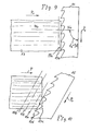
- 5 shows a top view of a wooden board 20, the fibers 21 of which run in the longitudinal direction, the cut marks 22 running perpendicularly thereto. The cut marks are those marks that can appear when sawing a wooden board according to the shape of the teeth. The distance between two saw marks at a cutting angle of 90 degrees is D 1 .
- FIG. 6 A blade 23 sawed in a similar manner with the method according to the invention or with the embodiment according to the invention is shown in FIG. 6.
- the sawing direction in the component according to FIG. 6, that is to say the direction of advance of the strip or the direction of movement of the strip is P 1 ; the feed movement of the wood was P and, as can clearly be seen, is the distance between two characteristic saw marks D 2 .
- These characteristic saw marks can be traced back to certain irregularities of the saw blades and, as can be seen from a sawn part, such saw marks occur regularly when circulating a band saw at certain, exactly the same intervals over the entire length of the wooden workpiece.
- the saw band or the saw frame is inclined from the vertical into an inclined position or whether the feed, that is to say the surface on which the bed 11 moves in the direction of the band, is inclined in a corresponding manner.
- FIG. 7 shows a diagram which qualitatively shows the dependence of the required sawing time V on the saw angle or.
- the embodiment according to the invention is essentially only effective in the case of materials which have structures made of and with wood fibers. Above all, these are naturally grown woods, boards pressed from wood fibers (chipboard), boards with wooden middle layers, such as blockboard or multilayer plywood boards. Homogeneous material or reacted with tightly fused fibers. very little or not at all to the change of the processing angle.
- chipsboard wood fibers
- wooden middle layers such as blockboard or multilayer plywood boards.
- the longitudinal fibers are gripped by the tips of the teeth and split or torn off.
- Fig. 8 shows a representation that makes the invention more plausible.
- a block of wood with fibers running in the longitudinal direction N 1 -N 1 can be seen , the direction of advance of which is indicated by P.
- the feed direction of the tape is P 1 .
- the direction of movement of the belt runs at a 90 degree angle to N 1 - N 1 ; this direction of movement is designated P 1A . If one considers the angle between the fiber direction N 1 -N 1 and the feed direction of the tape P gradually changed, s o is the angle obtained 75 degrees (direction P tape 1b). 60 degrees P lc , 45 degrees Pd and 30 degrees P le .
- the belt direction always runs against the feed direction and at an acute angle, measured from the line N 1 -N 1 in the direction of the feed of the belt against the direction of the feed of the wooden workpiece.
Landscapes
- Life Sciences & Earth Sciences (AREA)
- Engineering & Computer Science (AREA)
- Mechanical Engineering (AREA)
- Wood Science & Technology (AREA)
- Forests & Forestry (AREA)
- Debarking, Splitting, And Disintegration Of Timber (AREA)
- Dry Formation Of Fiberboard And The Like (AREA)
Applications Claiming Priority (2)
| Application Number | Priority Date | Filing Date | Title |
|---|---|---|---|
| DE3326843A DE3326843C2 (de) | 1983-07-26 | 1983-07-26 | Band- oder Gattersägemaschine |
| DE3326843 | 1983-07-26 |
Publications (1)
| Publication Number | Publication Date |
|---|---|
| EP0132837A1 true EP0132837A1 (fr) | 1985-02-13 |
Family
ID=6204907
Family Applications (1)
| Application Number | Title | Priority Date | Filing Date |
|---|---|---|---|
| EP84108761A Withdrawn EP0132837A1 (fr) | 1983-07-26 | 1984-07-25 | Scie à ruban ou à cadre à lames multiples |
Country Status (2)
| Country | Link |
|---|---|
| EP (1) | EP0132837A1 (fr) |
| DE (1) | DE3326843C2 (fr) |
Cited By (4)
| Publication number | Priority date | Publication date | Assignee | Title |
|---|---|---|---|---|
| DE19712695A1 (de) * | 1997-03-26 | 1998-10-01 | Siempelkamp Handling Sys Gmbh | Bandsäge |
| EP0867250A3 (fr) * | 1997-03-26 | 2000-04-05 | Siempelkamp Handling Systeme GmbH & Co. | Scie à ruban à lame de scie inclinée |
| WO2020041816A1 (fr) * | 2018-08-31 | 2020-03-05 | Leitinger Hans Peter | Lame de scie |
| AT17009U1 (fr) * | 2020-01-31 | 2021-02-15 | Leitinger Hans Peter |
Families Citing this family (2)
| Publication number | Priority date | Publication date | Assignee | Title |
|---|---|---|---|---|
| DK0612596T3 (da) * | 1993-02-25 | 1995-03-06 | Josef Neubauer | Naturtræsplade, naturtræslaminatplade og fremgangsmåde til at fremstille disse |
| NO940418L (no) * | 1993-02-25 | 1994-08-26 | Josef Neubauer | Naturtreplate eller laminert naturtreplate |
Citations (1)
| Publication number | Priority date | Publication date | Assignee | Title |
|---|---|---|---|---|
| FR1064207A (fr) * | 1952-10-08 | 1954-05-12 | Scie pour le travail du bois et autres matières à fibres dirigées |
Family Cites Families (3)
| Publication number | Priority date | Publication date | Assignee | Title |
|---|---|---|---|---|
| DE36336C (de) * | A. GOEDE in Berlin N., Chausseestr. 32 | Vorschubvorrichtung an Vollgattern mit Walzenvorschub | ||
| DE826640C (de) * | 1948-11-06 | 1952-01-03 | Josef Kramer | Bandsaegentisch |
| DE1924128C3 (de) * | 1969-05-12 | 1979-04-26 | Teves-Thompson Gmbh, 3013 Barsinghausen | Vorrichtung zum Drehen von Ventilen, vorzugsweise für Verbrennungskraftmaschinen |
-
1983
- 1983-07-26 DE DE3326843A patent/DE3326843C2/de not_active Expired
-
1984
- 1984-07-25 EP EP84108761A patent/EP0132837A1/fr not_active Withdrawn
Patent Citations (1)
| Publication number | Priority date | Publication date | Assignee | Title |
|---|---|---|---|---|
| FR1064207A (fr) * | 1952-10-08 | 1954-05-12 | Scie pour le travail du bois et autres matières à fibres dirigées |
Cited By (6)
| Publication number | Priority date | Publication date | Assignee | Title |
|---|---|---|---|---|
| DE19712695A1 (de) * | 1997-03-26 | 1998-10-01 | Siempelkamp Handling Sys Gmbh | Bandsäge |
| EP0867250A3 (fr) * | 1997-03-26 | 2000-04-05 | Siempelkamp Handling Systeme GmbH & Co. | Scie à ruban à lame de scie inclinée |
| WO2020041816A1 (fr) * | 2018-08-31 | 2020-03-05 | Leitinger Hans Peter | Lame de scie |
| AT16751U1 (de) * | 2018-08-31 | 2020-07-15 | Ing Hans Peter Leitinger | Sägeblatt |
| AT17009U1 (fr) * | 2020-01-31 | 2021-02-15 | Leitinger Hans Peter | |
| EP3858527A1 (fr) * | 2020-01-31 | 2021-08-04 | Hans-Peter Leitinger | Dispositif de sciage d'une lamelle à partir d'un substrat |
Also Published As
| Publication number | Publication date |
|---|---|
| DE3326843A1 (de) | 1985-02-14 |
| DE3326843C2 (de) | 1986-01-02 |
Similar Documents
| Publication | Publication Date | Title |
|---|---|---|
| DE3125191A1 (de) | Vorrichtung zur zufuehrung von holzbloecken in eine holzbearbeitungsmaschine | |
| DE2918622A1 (de) | Verfahren und vorrichtung zur spanenden zerlegung von baumstaemmen in allseitig bearbeitete holzerzeugnisse | |
| DE3720169A1 (de) | Saegevorrichtung | |
| EP0144003B1 (fr) | Dispositif pour la fabrication de bois équarri à partir de troncs d'arbre en y tranchant des planches sur les côtés opposés | |
| DE3244393C1 (de) | Verfahren zum Herstellen von allseitig bearbeiteten Holzerzeugnissen sowie Vorrichtung zur Durchfuehrung des Verfahrens | |
| DE3415932A1 (de) | Vorrichtung zur spanenden bearbeitung der seiten von holzstaemmen | |
| DE2010060B2 (de) | Holzbearbeitungsmaschine für Rundholz | |
| DE2714973A1 (de) | Verfahren und vorrichtung zum behandeln von an den kanten unbesaeumten rohbrettern | |
| EP1392102B1 (fr) | Dispositif d'emondage pour enlever les branches d'arbres vivants | |
| EP3858527A1 (fr) | Dispositif de sciage d'une lamelle à partir d'un substrat | |
| EP0132837A1 (fr) | Scie à ruban ou à cadre à lames multiples | |
| DE2820539C2 (de) | Verfahren zum Durchtrennen von Plattenmaterial sowie Einrichtung zur Durchführung dieses Verfahrens | |
| EP0036964B1 (fr) | Machine de sciage avec plusieurs lames circulaires | |
| DE2947993C2 (fr) | ||
| DE102004049699B4 (de) | Vorrichtung zum Sägen von langgestrecktem Sägegut | |
| DE2518359A1 (de) | Holzbearbeitungs-maschine | |
| CH683828A5 (de) | Verfahren zum Erzeugen von Nutzholz aus Baumstämmen oder Modeln, und Vorrichtung zum Durchführen des Verfahrens. | |
| EP3843926A1 (fr) | Lame de scie | |
| DE2235276B2 (de) | Vorrichtung zum Einbringen von Einschnitten oder Einstichen in der Holzoberfläche von Schnitt- und Kanthölzern | |
| EP0116606B1 (fr) | Dispositif de coupe pour couper des planches ou objets similaires | |
| DE69515661T2 (de) | Vorrichtung zum herstellen von seitlich gekrümmten holzwollefasern | |
| DE69504838T2 (de) | Messeranordnung und vorrichtung zum schneiden von holzwolle | |
| EP1365899A2 (fr) | Procede et dispositif pour decouper des bois ronds courbes dans un plan afin d'obtenir des produits ligneux | |
| DE70407C (fr) | ||
| DE3750604T2 (de) | Sägeverfahren und Vorrichtung für die Durchführung des Verfahrens. |
Legal Events
| Date | Code | Title | Description |
|---|---|---|---|
| PUAI | Public reference made under article 153(3) epc to a published international application that has entered the european phase |
Free format text: ORIGINAL CODE: 0009012 |
|
| AK | Designated contracting states |
Designated state(s): AT DE FR GB IT SE |
|
| 17P | Request for examination filed |
Effective date: 19850809 |
|
| 17Q | First examination report despatched |
Effective date: 19870212 |
|
| STAA | Information on the status of an ep patent application or granted ep patent |
Free format text: STATUS: THE APPLICATION IS DEEMED TO BE WITHDRAWN |
|
| 18D | Application deemed to be withdrawn |
Effective date: 19870723 |