EP0135220A1 - A holder for electronic detection element, comprising band attachment with pull force protection - Google Patents
A holder for electronic detection element, comprising band attachment with pull force protection Download PDFInfo
- Publication number
- EP0135220A1 EP0135220A1 EP84201100A EP84201100A EP0135220A1 EP 0135220 A1 EP0135220 A1 EP 0135220A1 EP 84201100 A EP84201100 A EP 84201100A EP 84201100 A EP84201100 A EP 84201100A EP 0135220 A1 EP0135220 A1 EP 0135220A1
- Authority
- EP
- European Patent Office
- Prior art keywords
- holder
- flap
- holder according
- detection element
- band
- Prior art date
- Legal status (The legal status is an assumption and is not a legal conclusion. Google has not performed a legal analysis and makes no representation as to the accuracy of the status listed.)
- Granted
Links
- 238000001514 detection method Methods 0.000 title claims abstract description 30
- 241001465754 Metazoa Species 0.000 claims abstract description 17
- 230000001174 ascending effect Effects 0.000 claims description 3
- 239000000463 material Substances 0.000 claims description 2
- 230000000694 effects Effects 0.000 description 4
- 238000012986 modification Methods 0.000 description 2
- 230000004048 modification Effects 0.000 description 2
- 229920003023 plastic Polymers 0.000 description 2
- 239000004033 plastic Substances 0.000 description 2
- 208000003251 Pruritus Diseases 0.000 description 1
- 238000013459 approach Methods 0.000 description 1
- 239000000039 congener Substances 0.000 description 1
- 238000010276 construction Methods 0.000 description 1
- 230000001627 detrimental effect Effects 0.000 description 1
- 230000005484 gravity Effects 0.000 description 1
- 230000007803 itching Effects 0.000 description 1
- 238000000034 method Methods 0.000 description 1
- 230000000717 retained effect Effects 0.000 description 1
- 239000007787 solid Substances 0.000 description 1
Images

Classifications
-
- A—HUMAN NECESSITIES
- A01—AGRICULTURE; FORESTRY; ANIMAL HUSBANDRY; HUNTING; TRAPPING; FISHING
- A01K—ANIMAL HUSBANDRY; AVICULTURE; APICULTURE; PISCICULTURE; FISHING; REARING OR BREEDING ANIMALS, NOT OTHERWISE PROVIDED FOR; NEW BREEDS OF ANIMALS
- A01K11/00—Marking of animals
- A01K11/006—Automatic identification systems for animals, e.g. electronic devices, transponders for animals
-
- A—HUMAN NECESSITIES
- A44—HABERDASHERY; JEWELLERY
- A44B—BUTTONS, PINS, BUCKLES, SLIDE FASTENERS, OR THE LIKE
- A44B11/00—Buckles; Similar fasteners for interconnecting straps or the like, e.g. for safety belts
- A44B11/005—Buckles combined with other articles, e.g. with receptacles
-
- A—HUMAN NECESSITIES
- A44—HABERDASHERY; JEWELLERY
- A44B—BUTTONS, PINS, BUCKLES, SLIDE FASTENERS, OR THE LIKE
- A44B11/00—Buckles; Similar fasteners for interconnecting straps or the like, e.g. for safety belts
- A44B11/006—Attachment of buckle to strap
-
- A—HUMAN NECESSITIES
- A44—HABERDASHERY; JEWELLERY
- A44B—BUTTONS, PINS, BUCKLES, SLIDE FASTENERS, OR THE LIKE
- A44B11/00—Buckles; Similar fasteners for interconnecting straps or the like, e.g. for safety belts
- A44B11/02—Buckles; Similar fasteners for interconnecting straps or the like, e.g. for safety belts frictionally engaging surface of straps
- A44B11/06—Buckles; Similar fasteners for interconnecting straps or the like, e.g. for safety belts frictionally engaging surface of straps with clamping devices
- A44B11/12—Buckles; Similar fasteners for interconnecting straps or the like, e.g. for safety belts frictionally engaging surface of straps with clamping devices turnable clamp
Definitions
- the invention concerns a holder for an electronic detection element adapted to be attached by means of a band around the neck or around a different part of the body of an animal to be detected.
- a detection element sometimes referred to as responder.
- responder Such an element is disclosed e.g..in Dutch patent application 77,11891 of applicants, or their corresponding British patent No. 1,577,920.
- the holder with the detection element always hangs in approximately the same place, preferably at the bottom of the neck of the animal, so that when the animal approaches the detection antenna, it will always bring the detection element at a predictable distance, at least within the range of the transceiver, in order to be identified with certainty.
- the holder with the detection element should have a given weight in order to be kept through gravity at the bottom of the neck of the animal. The weight of the hold-r with the detection element competes with the weight of the buckle often present at the top of the neck of the animal.
- the holder with detection element should therefore have so much weight that the loosely fitting collar will not turn around the neck of the animal.
- the mini-aturization of the identification systems has meanwhile progressed to the extent that the last generation of detection elements have dimensions and weights that are a fraction of the versions hitherto conventional. It may then be considered to attach such a detection element in a different place in or on the body of the animal. Most of the animals to be identified, however, will keep their collars even if such a different attachment place is possible, since one will wish to recognize the animal electronically but also visually, which is possible by applying a name and/or number on or about the collar.
- the problem of maintaining the detection element at the bottom of the neck of the animal will be felt more strongly, since the competing weight of the buckle on top of the neck will not or not appreciably decrease, while precisely the total weight of the detection element with the associated holder will strongly decrease.
- the integrated holder/buckle unit according to the invention may be fitted with a maximum band pull protection.This is necessary with many animals, since an animal, when being seized with the collar behind an obstacle, will try to break free. When the collar is made of a solid, wear-resistant material, substantial forces on the neck may be produced, with all detrimental effects thereof. To prevent this, the buckle can be constructed in such a manner dat inexceeding a predetermined maximum band pull, it releases the band.
- the detection element according to the invention will also be embedded in a loose block and be replaceably installed in the holder/buckle. In case of damage to the holder/buckle, the relative expensive detection element; may then be transferred into another.
- the holder/buckle has a different form and/or colour for different dealers; the detection element may then always keep the same form and be effectively manufactured in large series.
- Fig. 1 is a longitudinal section of a preferably synthetic plastics holder 1, wherein a detection element 2 diagrammatically shown is embedded. At the bottom of the holder there is pivotally provided a flap 3 at one end at 4, which flap serves for clamping one of the ends of a band 6. In the closed position of the flap 3 shown, this is secured by lugs 5 (see also Fig. 2). For the purpose of clamping the free end of the band 6, the valve 3 is fitted adjacent the pivoted end with a boss7 which, in the closed position of the flap 3, extends to adjacent a rib 8 of the holder 1 opposite to boss?.
- the band end can be passed freely between the boss7 and the rib 8 and be pulled underneath the responder 2 and again be conducted at the other end of the responder through a slot 9 in the holder in outward direction.
- the band In closing the flap , the band is fixedly clamped between the boss7 and the rib 8.
- the other end of the band (at the right-hand side in the drawing) has a looped form and is passed around a pin 10 installed in the holder, said pin being preferably designed as a shear pin.
- the embodiment shown in Fig. 3 deviates from the embodiment shown in Fig. 2 in that the flap 3 is fitted with a cavity for receiving the responder 2.
- the responder may again be embedded in the cavity of the flap 3 and consequently be integral with the flap , but, as shown in Fig. 3,may also be provided with retaining lugs 11, which are adapted to detachably retain through snap action a loose responder block.
- the free band end in this embodiment is conducted along the top of the responder 2.
- the responder 2 is embedded in a cavity of the holder 1 or detachably installed therein as a responder block.
- Both ends of the band 6 with associated flaps 40, 41 which again are adapted for coaction with corresponding lugs 42, 43, can be fastened.
- both band ends are inserted via slots 44, 45 in the holder, while said ends come to lie on the responder or the responder block.
- transverse ribs 46, 47 of the holder which are hollow at the bottom. In said cavities fit correspondingly curved half-round end edges 48 of the otherwise flat flaps , as shown in Fig. 5.
- the flaps as shown by arrows 49, can be swivelled upwardly with their flat ends, while the curved end edges turn in the cavities of the ribs.
- the band ends, in the upwardly turned position of the flaps are inserted in the holder and subsequently clamped with the free edge of the curved end edges of the flaps against the lower edge of the slots 44 and 45 by bringing the flaps in the position shown.
- the free edges of the curved end edges of the flaps may be fitted with teeth 50, as shown in Fig. 5.
- the maximum band pull force that can be exerted without loosening the band is determined by the strength of the half-round end edges 48.
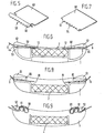
- Figs. 6 and 7 show a variant of Figs. 4 and 5, in which the rotary flaps have been replaced by substantially flat slides 60, each having an end edge 61 bent at an angle slightly more than 90°.
- the ribs 62 of the holder corresponding to the ribs 46, 47 are now flat at the bottom and, together with the opposite lower edges of the slots 44, form a slightly wedge-shaped space accommodating the slides.
- the bent edge 61 of each slide is adapted for coaction with an ascending portion 63 of the lower edges of the slots44 for clamping the band ends. To this effect, the bent edges 61 may again be fitted with teeth 64, as shown in Fig. 7.
- Fig. 8 shows a variant, in which instead of a slide 60, as shown in Fig. 7, there is employed a wedge 80 fitted at the bottom with teeth.
- the maximum band pull force is now determined by the ribs,62 designed as shear pins.
- the responder block 2 is detachably retained in the appropriate cavity in the holder by retaining lugs 81, which are comparable with the retaining lugs 11 of Fig. 3.
- Fig. 9 finally shows a variant in which the band ends are each provided between and about three ribs 90, 91 and 92 integral with the holder and designed as shear pins.
Landscapes
- Life Sciences & Earth Sciences (AREA)
- Environmental Sciences (AREA)
- Birds (AREA)
- Zoology (AREA)
- Animal Husbandry (AREA)
- Biodiversity & Conservation Biology (AREA)
- Package Frames And Binding Bands (AREA)
- Clamps And Clips (AREA)
- Credit Cards Or The Like (AREA)
Abstract
Description
- The invention concerns a holder for an electronic detection element adapted to be attached by means of a band around the neck or around a different part of the body of an animal to be detected.
- It is necessary for electronic identification that the object to be identified is provided with a detection element, sometimes referred to as responder. Such an element is disclosed e.g..in Dutch patent application 77,11891 of applicants, or their corresponding British patent No. 1,577,920.
- It is conventional to embed such a detection element in a synthetic plastics holder, which is attacked to a collar the two ends of which are subsequently buckled together. It is necessary now that the holder with the detection element always hangs in approximately the same place, preferably at the bottom of the neck of the animal, so that when the animal approaches the detection antenna, it will always bring the detection element at a predictable distance, at least within the range of the transceiver, in order to be identified with certainty. In practice, the holder with the detection element should have a given weight in order to be kept through gravity at the bottom of the neck of the animal. The weight of the hold-r with the detection element competes with the weight of the buckle often present at the top of the neck of the animal. In order to remain at the bottom of the neck, the holder with detection element should therefore have so much weight that the loosely fitting collar will not turn around the neck of the animal. This has resulted in rather heavy and voluminous holders, which, due to their volume, reached the required weight for compensating the counterweight of the buckle, but which became at the same time unnecessarily sensitive, due to their dimensions,to external damage caused by congeners of the animal or due to their being caught behind obstacles with which the animal comes into contact unconsciously or precisely very consciously in order to get rid of itching.
- The mini-aturization of the identification systems has meanwhile progressed to the extent that the last generation of detection elements have dimensions and weights that are a fraction of the versions hitherto conventional. It may then be considered to attach such a detection element in a different place in or on the body of the animal. Most of the animals to be identified, however, will keep their collars even if such a different attachment place is possible, since one will wish to recognize the animal electronically but also visually, which is possible by applying a name and/or number on or about the collar.
- If therefore, even though it is technically possible to install the detection element elsewhere, perhaps with a different, more expensive method, the animals will yet continue to wear collars in large numbers, it is advantageous to use said collar to install the miniaturized detection elements in a simple manner.
- If the dimensions of the detection element are reduced from e.g. about 150x60x25 mm to about 60x35x12 mm or less in the near future,the problem of maintaining the detection element at the bottom of the neck of the animal will be felt more strongly, since the competing weight of the buckle on top of the neck will not or not appreciably decrease, while precisely the total weight of the detection element with the associated holder will strongly decrease.
- It is an object of the invention to eliminate the above problems, to which effect a holder of the above- described type is characterized in that the holder is fitted with a cavity for receiving the detection element and with at least one clamping member for adjustably clamping a band end.
- According to a further embodiment of the inventive idea, furthermore the integrated holder/buckle unit according to the invention may be fitted with a maximum band pull protection.This is necessary with many animals, since an animal, when being seized with the collar behind an obstacle, will try to break free. When the collar is made of a solid, wear-resistant material, substantial forces on the neck may be produced, with all detrimental effects thereof. To prevent this, the buckle can be constructed in such a manner dat inexceeding a predetermined maximum band pull, it releases the band. In addition to being adapted to be embedded in the holder, the detection element according to the invention will also be embedded in a loose block and be replaceably installed in the holder/buckle. In case of damage to the holder/buckle, the relative expensive detection element; may then be transferred into another.
- It is also possible that the holder/buckle has a different form and/or colour for different dealers; the detection element may then always keep the same form and be effectively manufactured in large series.
- Some embodiments of the construction of the invention will now be described by way of example, with reference to the accompanying drawings, in which:
- Fig. 1 is a longitudinal section of a first embodiment of a holder according to the invention;
- Fig. 2 is a bottom view of the holder shown in Fig. 1 without flap and collar;
- Fig. 3 is a longitudinal section of the second embodiment of a holder according to the invention;
- Fig. 4`is a longitudinal section of a third embodiment of a holder according to the invention;
- Fig. 5 shows a detail of Fig. 4;
- Fig. 6 shows a variant of Fig. 4;
- Fig. 7 shows a detail of Fig. 6; and
- Figs. 8 and 9 show two other embodiments of a holder according to the invention.
- Fig. 1 is a longitudinal section of a preferably
synthetic plastics holder 1, wherein adetection element 2 diagrammatically shown is embedded. At the bottom of the holder there is pivotally provided aflap 3 at one end at 4, which flap serves for clamping one of the ends of aband 6. In the closed position of theflap 3 shown, this is secured by lugs 5 (see also Fig. 2). For the purpose of clamping the free end of theband 6, thevalve 3 is fitted adjacent the pivoted end with a boss7 which, in the closed position of theflap 3, extends to adjacent arib 8 of theholder 1 opposite to boss?. - In the opened position of the
flap 3, the band end can be passed freely between the boss7 and therib 8 and be pulled underneath theresponder 2 and again be conducted at the other end of the responder through aslot 9 in the holder in outward direction.In closing the flap , the band is fixedly clamped between the boss7 and therib 8. The other end of the band (at the right-hand side in the drawing) has a looped form and is passed around apin 10 installed in the holder, said pin being preferably designed as a shear pin. - The embodiment shown in Fig. 3 deviates from the embodiment shown in Fig. 2 in that the
flap 3 is fitted with a cavity for receiving theresponder 2. The responder may again be embedded in the cavity of theflap 3 and consequently be integral with the flap , but, as shown in Fig. 3,may also be provided with retaininglugs 11, which are adapted to detachably retain through snap action a loose responder block. The free band end in this embodiment is conducted along the top of theresponder 2. - In the embodiment shown in Figs. 4 and 6, the
responder 2 is embedded in a cavity of theholder 1 or detachably installed therein as a responder block. Both ends of theband 6 with associatedflaps corresponding lugs slots slots transverse ribs 46, 47 of the holder, which are hollow at the bottom. In said cavities fit correspondingly curved half-round end edges 48 of the otherwise flat flaps , as shown in Fig. 5. The flaps , as shown byarrows 49, can be swivelled upwardly with their flat ends, while the curved end edges turn in the cavities of the ribs. The band ends, in the upwardly turned position of the flaps , are inserted in the holder and subsequently clamped with the free edge of the curved end edges of the flaps against the lower edge of theslots - In order to increase the clamping effect, the free edges of the curved end edges of the flaps may be fitted with
teeth 50, as shown in Fig. 5. - When in this embodiment a loose responder block is employed, the flat portions of the flaps are so long that in the closed position they partly lie on the responder block, as shown in Fig.4.
- The maximum band pull force that can be exerted without loosening the band, is determined by the strength of the half-
round end edges 48. - Figs. 6 and 7 show a variant of Figs. 4 and 5, in which the rotary flaps have been replaced by substantially
flat slides 60, each having anend edge 61 bent at an angle slightly more than 90°. Theribs 62 of the holder corresponding to theribs 46, 47 are now flat at the bottom and, together with the opposite lower edges of theslots 44, form a slightly wedge-shaped space accommodating the slides. Thebent edge 61 of each slide is adapted for coaction with anascending portion 63 of the lower edges of the slots44 for clamping the band ends. To this effect, thebent edges 61 may again be fitted withteeth 64, as shown in Fig. 7. - When the band pull force exceeds a given value, the slide passes the
ascending portion 63. - Fig. 8 shows a variant, in which instead of a
slide 60, as shown in Fig. 7, there is employed awedge 80 fitted at the bottom with teeth. The maximum band pull force is now determined by the ribs,62 designed as shear pins. In this embodiment, furthermore theresponder block 2 is detachably retained in the appropriate cavity in the holder by retaininglugs 81, which are comparable with theretaining lugs 11 of Fig. 3. - Fig. 9 finally shows a variant in which the band ends are each provided between and about three
ribs - It is observed that after the foregoing, various modifications are obvious to one skilled in the art. For instance, the responder could be placed e.g. in a different position in the holder. Such modifications are deemed not to'depart from the scope of the invention.
Claims (16)
Priority Applications (1)
| Application Number | Priority Date | Filing Date | Title |
|---|---|---|---|
| AT84201100T ATE32973T1 (en) | 1983-07-27 | 1984-07-26 | HOLDER FOR AN ELECTRONIC DETECTION ELEMENT WITH TAPE FASTENING MEANS. |
Applications Claiming Priority (2)
| Application Number | Priority Date | Filing Date | Title |
|---|---|---|---|
| NL8302684 | 1983-07-27 | ||
| NL8302684A NL8302684A (en) | 1983-07-27 | 1983-07-27 | HOUSING AN ELECTRONIC DETECTION ELEMENT FUNCTIONING AS AN INTEGRAL PART OF A BUCKLE. |
Publications (2)
| Publication Number | Publication Date |
|---|---|
| EP0135220A1 true EP0135220A1 (en) | 1985-03-27 |
| EP0135220B1 EP0135220B1 (en) | 1988-03-16 |
Family
ID=19842210
Family Applications (1)
| Application Number | Title | Priority Date | Filing Date |
|---|---|---|---|
| EP84201100A Expired EP0135220B1 (en) | 1983-07-27 | 1984-07-26 | A holder for electronic detection element, comprising band attachment with pull force protection |
Country Status (6)
| Country | Link |
|---|---|
| US (1) | US4612719A (en) |
| EP (1) | EP0135220B1 (en) |
| AT (1) | ATE32973T1 (en) |
| CA (1) | CA1232043A (en) |
| DE (1) | DE3469843D1 (en) |
| NL (1) | NL8302684A (en) |
Cited By (5)
| Publication number | Priority date | Publication date | Assignee | Title |
|---|---|---|---|---|
| NL8502004A (en) * | 1985-07-11 | 1986-02-03 | Molentechniek B V | Code carrier for animal collar - has thin body with strap passage and flexible strip across side opening(s) |
| EP0285242A3 (en) * | 1987-03-30 | 1989-11-08 | Elexis Corporation | Electronic flea repelling device with means for carrying collar strap behind the device housing |
| WO2018061003A1 (en) * | 2016-09-28 | 2018-04-05 | Scr Engineers Ltd | Holder for a smart monitoring tag for cows |
| EP3656213A1 (en) | 2018-11-20 | 2020-05-27 | InnoCow GmbH | Electronic device for the detection and/or transmission of sensor data of an animal |
| EP3656214A1 (en) | 2018-11-20 | 2020-05-27 | InnoCow GmbH | Electronic device for the detection and/or transmission of sensor data of an animal |
Families Citing this family (52)
| Publication number | Priority date | Publication date | Assignee | Title |
|---|---|---|---|---|
| DE69324132T2 (en) * | 1992-01-23 | 1999-10-28 | Saab-Scania Combitech Ab, Joenkoeping | WIRELESS INFORMATION TRANSFER DEVICE |
| US5454350A (en) * | 1993-03-30 | 1995-10-03 | Betheil; Stephen M. | Electronic dialing attachment for a pet collar |
| SE506447C2 (en) * | 1996-06-03 | 1997-12-15 | Mia Adler | Device for signs on horses |
| US7374081B2 (en) * | 1997-03-12 | 2008-05-20 | Precision Dynamics Corporation | Identification device having reusable transponder |
| US7198190B2 (en) * | 1997-03-12 | 2007-04-03 | Dodge Juhan | Identification device having reusable transponder |
| USD409803S (en) * | 1997-07-10 | 1999-05-11 | John Jerome Yoka | Pet locating collar |
| US6067018A (en) * | 1998-12-22 | 2000-05-23 | Joan M. Skelton | Lost pet notification system |
| USD555298S1 (en) * | 2006-02-10 | 2007-11-13 | Multi-Vet Ltd. | Wearable pet reservoir |
| US20080021919A1 (en) * | 2006-06-08 | 2008-01-24 | Db Industries, Inc. | Method for Retrofitting Safety Equipment Items and Database |
| US20080021718A1 (en) * | 2006-06-08 | 2008-01-24 | Db Industries, Inc. | Centralized Database of Information Related to Inspection of Safety Equipment Items Inspection and Method |
| US20080021905A1 (en) * | 2006-06-08 | 2008-01-24 | Db Industries, Inc. | Direct Data Input for Database for Safety Equipment Items and Method |
| US20080009185A1 (en) * | 2006-06-08 | 2008-01-10 | D B Industries, Inc. | Retrofittable radio frequency identification connector |
| US20080021717A1 (en) * | 2006-06-08 | 2008-01-24 | Db Industries, Inc. | Method of Facilitating Controlled Flow of Information for Safety Equipment Items and Database Related Thereto |
| US7843349B2 (en) * | 2006-11-03 | 2010-11-30 | D B Industries, Inc. | Retrofittable radio frequency identification connector |
| US20080106413A1 (en) * | 2006-11-03 | 2008-05-08 | D B Industries, Inc. | Radio frequency identification connector |
| US20080106088A1 (en) * | 2006-11-03 | 2008-05-08 | D B Industries, Inc. | Retrofittable radio frequency identification connector |
| US20080106398A1 (en) * | 2006-11-03 | 2008-05-08 | D B Industries, Inc. | Radio frequency identification connector |
| USD601151S1 (en) * | 2007-01-31 | 2009-09-29 | Symbol Technologies, Inc. | Bottom portion of a finger mounted device |
| US20080303668A1 (en) * | 2007-06-07 | 2008-12-11 | D B Industries, Inc. | Retrofittable radio frequency identification connector |
| TR201808135T4 (en) | 2007-08-31 | 2018-07-23 | 3M Innovative Properties Co | Determination of the status of personal protective products according to at least one criterion. |
| ES2828075T3 (en) | 2007-08-31 | 2021-05-25 | 3M Innovative Properties Co | Determination of states of components removably coupled to personal protective equipment |
| USD657098S1 (en) * | 2011-05-09 | 2012-04-03 | E-Collar Technologies, Inc. | Animal training collar device |
| USD661846S1 (en) * | 2011-12-13 | 2012-06-12 | Sunbeam Products, Inc. | Bark collar housing |
| USD665952S1 (en) * | 2012-01-16 | 2012-08-21 | Guo xu wei | Receiver |
| USD673334S1 (en) * | 2012-01-16 | 2012-12-25 | Guo xu wei | Receiver |
| USD734900S1 (en) | 2013-12-31 | 2015-07-21 | i4c Innovations Inc. | Electronic dog collar |
| USD745229S1 (en) | 2013-12-31 | 2015-12-08 | i4c Innovations Inc. | Electronic module for a dog collar |
| USD748350S1 (en) | 2013-12-31 | 2016-01-26 | i4c Innovations Inc. | Electronic dog collar |
| USD747566S1 (en) | 2013-12-31 | 2016-01-12 | i4c Innovations Inc. | Electronic dog collar |
| RU2706300C2 (en) | 2015-09-01 | 2019-11-15 | 3М Инновейтив Пропертиз Компани | Transmission of security-related contextual information in system comprising individual protection means |
| KR102375215B1 (en) | 2016-03-07 | 2022-03-16 | 쓰리엠 이노베이티브 프로퍼티즈 캄파니 | Intelligent safety monitoring and analysis system for personal protective equipment |
| USD798003S1 (en) * | 2016-06-17 | 2017-09-19 | Shenzhen YueHuanYu Ribbon Co., Ltd. | Stop barking device with remote control |
| USD815366S1 (en) * | 2016-07-18 | 2018-04-10 | Shu-Hui Kao | Racing pigeon foot ring |
| USD815367S1 (en) * | 2016-07-19 | 2018-04-10 | Shu-Hui Kao | Racing pigeon foot ring |
| USD834769S1 (en) * | 2016-11-30 | 2018-11-27 | Jian Wen | Bark control |
| USD850733S1 (en) * | 2018-02-11 | 2019-06-04 | Fuliang Dong | Stop barking device |
| USD850732S1 (en) * | 2018-02-11 | 2019-06-04 | Fuliang Dong | Stop barking device |
| USD898309S1 (en) * | 2019-05-28 | 2020-10-06 | Xiaoni Yang | Remote controlled dog training device |
| USD898308S1 (en) * | 2019-05-28 | 2020-10-06 | Shenzhen Tianzhe Science And Technology Co., Limited | Remote controlled dog training device |
| USD898307S1 (en) * | 2019-05-28 | 2020-10-06 | Xiaoni Yang | Remote controlled dog training device |
| USD929051S1 (en) * | 2019-10-01 | 2021-08-24 | Shenzhen Patpet Technology CO., LTD | Receiver of dog training collar |
| US20220272948A1 (en) * | 2019-11-22 | 2022-09-01 | Gallagher eShepherd Pty Ltd | Wearable electronic collar for animals |
| USD929682S1 (en) * | 2020-01-07 | 2021-08-31 | Shenzhen Patpet Technology CO., LTD | No bark collar device |
| USD976730S1 (en) * | 2020-08-17 | 2023-01-31 | Hills Pet Nutrition, Inc. | Sensor module |
| USD925143S1 (en) * | 2020-10-20 | 2021-07-13 | Shenzhen Smart Pet Technology Co., Ltd | Stop barking device |
| USD925141S1 (en) * | 2021-01-12 | 2021-07-13 | Shenzhen Xinchi Network & Tech Co., Ltd. | Bark collar device for dog |
| USD964667S1 (en) * | 2021-09-03 | 2022-09-20 | Xijian Mo | Dog training device |
| USD972236S1 (en) * | 2021-10-22 | 2022-12-06 | Shenzhen Hongke Gelin Technology Co., LTD | Bark training collar |
| USD965925S1 (en) * | 2021-11-04 | 2022-10-04 | Xiao Zhu | Dog training receiver |
| USD965926S1 (en) * | 2021-11-23 | 2022-10-04 | Xijian Mo | Dog trainer receiver |
| USD966633S1 (en) * | 2022-04-01 | 2022-10-11 | Shenzhen Smart Pet Technology Co., Ltd | Dog training receiver |
| USD967569S1 (en) * | 2022-05-12 | 2022-10-18 | Yi Wei | Device for wireless dog fence system |
Citations (8)
| Publication number | Priority date | Publication date | Assignee | Title |
|---|---|---|---|---|
| US3432895A (en) * | 1967-05-15 | 1969-03-18 | Justin Belt Co | Adapter for connecting a belt buckle with a belt |
| DE2042043A1 (en) * | 1969-10-06 | 1971-04-15 | J T Posey Co | Tether closure |
| FR2127269A6 (en) * | 1971-03-02 | 1972-10-13 | Boeuf Julien | |
| FR2222972A1 (en) * | 1973-03-30 | 1974-10-25 | Debot Guy | Belt for masculine or feminine garments - with fastening device having a small purse with simple fastening attached |
| DE7439916U (en) * | 1975-04-17 | Fildan G | Holder for adjustable shoulder straps of bodices | |
| DE2817939A1 (en) * | 1977-04-26 | 1978-11-09 | Foss Electric As N | IDENTIFICATION SYSTEM |
| US4185791A (en) * | 1977-10-24 | 1980-01-29 | Takata Kojyo Co., Ltd. | Device for preventing a belt from being pulled from a retractor |
| EP0023377A1 (en) * | 1979-07-26 | 1981-02-04 | Istvan Lörincz | Strap for marking cattle |
Family Cites Families (12)
| Publication number | Priority date | Publication date | Assignee | Title |
|---|---|---|---|---|
| GB686380A (en) * | ||||
| GB190802487A (en) * | 1908-02-04 | 1908-04-14 | William Joseph Gordon | Improvements in Buckles. |
| US965425A (en) * | 1909-05-04 | 1910-07-26 | Sherod Warren | Buckle. |
| US1265324A (en) * | 1917-05-26 | 1918-05-07 | Augustus A Greene | Buckle. |
| US1508963A (en) * | 1923-12-01 | 1924-09-16 | Dorf Herman | Belt buckle |
| US1606849A (en) * | 1924-10-27 | 1926-11-16 | Spear Alfred | Combined receptacle and belt buckle |
| US1578468A (en) * | 1925-06-10 | 1926-03-30 | Rankin Julian | Combined match box and belt buckle |
| US2442266A (en) * | 1945-04-09 | 1948-05-25 | Frank L Davis | Cargo tie-down |
| GB1391610A (en) * | 1971-05-10 | 1975-04-23 | Ici Ltd | Coating compositions |
| US4113157A (en) * | 1976-03-08 | 1978-09-12 | Woodbury Dean F | Compartmented receptacle |
| GB1577920A (en) * | 1976-11-01 | 1980-10-29 | Nedap Nv | Detection plate for identification systems |
| NL7709183A (en) * | 1977-08-19 | 1979-02-21 | Boer G Erven Bv De | CLAMP BUCKLE FOR A SEAT GINGEL AND / OR COWNECK BELT. |
-
1983
- 1983-07-27 NL NL8302684A patent/NL8302684A/en not_active Application Discontinuation
-
1984
- 1984-07-26 AT AT84201100T patent/ATE32973T1/en active
- 1984-07-26 EP EP84201100A patent/EP0135220B1/en not_active Expired
- 1984-07-26 DE DE8484201100T patent/DE3469843D1/en not_active Expired
- 1984-07-27 CA CA000459850A patent/CA1232043A/en not_active Expired
- 1984-07-27 US US06/635,123 patent/US4612719A/en not_active Expired - Fee Related
Patent Citations (8)
| Publication number | Priority date | Publication date | Assignee | Title |
|---|---|---|---|---|
| DE7439916U (en) * | 1975-04-17 | Fildan G | Holder for adjustable shoulder straps of bodices | |
| US3432895A (en) * | 1967-05-15 | 1969-03-18 | Justin Belt Co | Adapter for connecting a belt buckle with a belt |
| DE2042043A1 (en) * | 1969-10-06 | 1971-04-15 | J T Posey Co | Tether closure |
| FR2127269A6 (en) * | 1971-03-02 | 1972-10-13 | Boeuf Julien | |
| FR2222972A1 (en) * | 1973-03-30 | 1974-10-25 | Debot Guy | Belt for masculine or feminine garments - with fastening device having a small purse with simple fastening attached |
| DE2817939A1 (en) * | 1977-04-26 | 1978-11-09 | Foss Electric As N | IDENTIFICATION SYSTEM |
| US4185791A (en) * | 1977-10-24 | 1980-01-29 | Takata Kojyo Co., Ltd. | Device for preventing a belt from being pulled from a retractor |
| EP0023377A1 (en) * | 1979-07-26 | 1981-02-04 | Istvan Lörincz | Strap for marking cattle |
Cited By (5)
| Publication number | Priority date | Publication date | Assignee | Title |
|---|---|---|---|---|
| NL8502004A (en) * | 1985-07-11 | 1986-02-03 | Molentechniek B V | Code carrier for animal collar - has thin body with strap passage and flexible strip across side opening(s) |
| EP0285242A3 (en) * | 1987-03-30 | 1989-11-08 | Elexis Corporation | Electronic flea repelling device with means for carrying collar strap behind the device housing |
| WO2018061003A1 (en) * | 2016-09-28 | 2018-04-05 | Scr Engineers Ltd | Holder for a smart monitoring tag for cows |
| EP3656213A1 (en) | 2018-11-20 | 2020-05-27 | InnoCow GmbH | Electronic device for the detection and/or transmission of sensor data of an animal |
| EP3656214A1 (en) | 2018-11-20 | 2020-05-27 | InnoCow GmbH | Electronic device for the detection and/or transmission of sensor data of an animal |
Also Published As
| Publication number | Publication date |
|---|---|
| NL8302684A (en) | 1985-02-18 |
| CA1232043A (en) | 1988-01-26 |
| US4612719A (en) | 1986-09-23 |
| EP0135220B1 (en) | 1988-03-16 |
| DE3469843D1 (en) | 1988-04-21 |
| ATE32973T1 (en) | 1988-04-15 |
Similar Documents
| Publication | Publication Date | Title |
|---|---|---|
| EP0135220B1 (en) | A holder for electronic detection element, comprising band attachment with pull force protection | |
| AU2016250901B2 (en) | Animal tag | |
| US3411233A (en) | Retractable fishhook | |
| US4473926A (en) | Adjusting device for seat belt | |
| US5226254A (en) | Assembly for insect trap | |
| US3267603A (en) | Fish grapple | |
| US5367818A (en) | Retractable snagproof fish hook system | |
| US2634539A (en) | Device for retrieving spinners or the like | |
| US5351435A (en) | Device to facilitate removal of juvenile and female crabs from the inside of crab traps and method of use thereof | |
| US3526987A (en) | Connector for animal identification tags | |
| IE940321A1 (en) | Non-snagging animal ear tags | |
| SE455261B (en) | BAND CLIP WITH SPRING LOADED CLAMP ORGAN | |
| US5115953A (en) | Knife scabbard with preloaded and locked insert panel for improved knife retention | |
| EP3514021B1 (en) | Seat belt connector | |
| WO1995009531A1 (en) | A trap for trapping and possibly killing of animals, especially small ones | |
| US4468880A (en) | Hook attachment/line tie | |
| US3461586A (en) | Method of and tag for identifying animals | |
| US2973887A (en) | Form to be used with garment hanger | |
| US1929843A (en) | Wire bale-tie | |
| US5497940A (en) | Mail box signaling device | |
| US2948985A (en) | Trap-type fish hook | |
| EP0193669A1 (en) | Safety stirrup | |
| US968279A (en) | Combined cattle-guard and halter. | |
| US20250137283A1 (en) | Metal fence post topper with locking clip | |
| US3226876A (en) | Releasable float for trawl nets |
Legal Events
| Date | Code | Title | Description |
|---|---|---|---|
| PUAI | Public reference made under article 153(3) epc to a published international application that has entered the european phase |
Free format text: ORIGINAL CODE: 0009012 |
|
| AK | Designated contracting states |
Designated state(s): AT BE CH DE FR GB IT LI NL SE |
|
| 17P | Request for examination filed |
Effective date: 19850909 |
|
| 17Q | First examination report despatched |
Effective date: 19860910 |
|
| ITF | It: translation for a ep patent filed | ||
| GRAA | (expected) grant |
Free format text: ORIGINAL CODE: 0009210 |
|
| AK | Designated contracting states |
Kind code of ref document: B1 Designated state(s): AT BE CH DE FR GB IT LI NL SE |
|
| REF | Corresponds to: |
Ref document number: 32973 Country of ref document: AT Date of ref document: 19880415 Kind code of ref document: T |
|
| REF | Corresponds to: |
Ref document number: 3469843 Country of ref document: DE Date of ref document: 19880421 |
|
| ET | Fr: translation filed | ||
| PLBE | No opposition filed within time limit |
Free format text: ORIGINAL CODE: 0009261 |
|
| STAA | Information on the status of an ep patent application or granted ep patent |
Free format text: STATUS: NO OPPOSITION FILED WITHIN TIME LIMIT |
|
| 26N | No opposition filed | ||
| PG25 | Lapsed in a contracting state [announced via postgrant information from national office to epo] |
Ref country code: GB Effective date: 19890726 Ref country code: AT Effective date: 19890726 |
|
| PG25 | Lapsed in a contracting state [announced via postgrant information from national office to epo] |
Ref country code: SE Effective date: 19890727 |
|
| PG25 | Lapsed in a contracting state [announced via postgrant information from national office to epo] |
Ref country code: LI Effective date: 19890731 Ref country code: CH Effective date: 19890731 Ref country code: BE Effective date: 19890731 |
|
| BERE | Be: lapsed |
Owner name: NEDERLANDSCHE APPARATENFABRIEK NEDAP N.V. Effective date: 19890731 |
|
| PG25 | Lapsed in a contracting state [announced via postgrant information from national office to epo] |
Ref country code: NL Effective date: 19900201 |
|
| NLV4 | Nl: lapsed or anulled due to non-payment of the annual fee | ||
| GBPC | Gb: european patent ceased through non-payment of renewal fee | ||
| PG25 | Lapsed in a contracting state [announced via postgrant information from national office to epo] |
Ref country code: FR Free format text: LAPSE BECAUSE OF NON-PAYMENT OF DUE FEES Effective date: 19900330 |
|
| REG | Reference to a national code |
Ref country code: CH Ref legal event code: PL |
|
| PG25 | Lapsed in a contracting state [announced via postgrant information from national office to epo] |
Ref country code: DE Effective date: 19900403 |
|
| REG | Reference to a national code |
Ref country code: FR Ref legal event code: ST |
|
| EUG | Se: european patent has lapsed |
Ref document number: 84201100.9 Effective date: 19900418 |