EP0136410A2 - Schienenbefestigung mit verstellbarer Schienenunterlagsplatte - Google Patents
Schienenbefestigung mit verstellbarer Schienenunterlagsplatte Download PDFInfo
- Publication number
- EP0136410A2 EP0136410A2 EP84107317A EP84107317A EP0136410A2 EP 0136410 A2 EP0136410 A2 EP 0136410A2 EP 84107317 A EP84107317 A EP 84107317A EP 84107317 A EP84107317 A EP 84107317A EP 0136410 A2 EP0136410 A2 EP 0136410A2
- Authority
- EP
- European Patent Office
- Prior art keywords
- rail
- fastening
- track
- base plate
- track width
- Prior art date
- Legal status (The legal status is an assumption and is not a legal conclusion. Google has not performed a legal analysis and makes no representation as to the accuracy of the status listed.)
- Granted
Links
Images
Classifications
-
- E—FIXED CONSTRUCTIONS
- E01—CONSTRUCTION OF ROADS, RAILWAYS, OR BRIDGES
- E01B—PERMANENT WAY; PERMANENT-WAY TOOLS; MACHINES FOR MAKING RAILWAYS OF ALL KINDS
- E01B9/00—Fastening rails on sleepers, or the like
- E01B9/38—Indirect fastening of rails by using tie-plates or chairs; Fastening of rails on the tie-plates or in the chairs
- E01B9/40—Tie-plates for flat-bottom rails
Definitions
- the invention relates to a rail fastening with adjustable rail base plate, provided with support ribs and mounting holes.
- Such rail fastenings enable the rail track width to be corrected by moving the base plate while maintaining the fastening points in the threshold.
- the lateral position of the rail fastening by moving the rail base plate in the transverse direction of the rail is corrected by an eccentric insert in the fastening hole of the rail base plate, which causes a side displacement of the rail base plate by twisting.
- the transverse displacement of the track base plate by schrägge - put to achieve long-holes and thereby allow a variation of the track width.
- the DD-PS 113 781 allows only a slight side adjustment, the DE-GM 1775 242 does not have a clear side fixation, so that a lateral displacement cannot be ruled out when the spring-mounted rail washer plate is passed over, especially in curves .
- the invention has for its object to provide a rail fastening of the type mentioned, which also allows larger track width changes, with a clear lateral position fixing of the rail base plate is guaranteed.
- the mounting holes for the sleeper screws have a different distance from the support rib arranged on the same side of the rail base.
- the rail base plates of a track are designed with different hole spacing differences.
- variable rail fastening makes it possible to vary the track width in several stages without additional components. Due to the particularly simple and clear design of the subject matter of the invention, it is possible to have this track width variation carried out by assistants without technical training. Another advantage is that. that a proposed change in track width can be carried out without additional measurement and adjustment work, since the change in track width is fixed to an intended dimension by the position of the rail base plate.
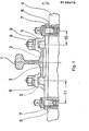
- the rail 1 lies on the threshold 4 over a damping pad 2 and a rail base plate 3.
- Sleeper screws 6 connect the rail base plate 3 through fastening holes 7 via a dowel to the sleeper 4.
- the rail 1 is laterally fixed by lateral support of the rail foot on the support ribs 5.
- hook screws 8 are fastened in a known manner, which secure the rail 1 Hold down elastically or rigidly with hold-down device 9 on the rail foot.
- the respective distance between the support rib 5 and the mounting hole 7 of the rail base plate is different on the different sides.
- the exemplary embodiment shows a small distance 10 and a large distance 11.
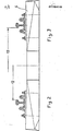
- the desired widening of the track from 1000 mm in accordance with FIG. 2 to 1067 mm in accordance with FIG. 3 is then achieved by turning over both rail fastenings of the track.
- a rail fastening of the track can be formed with a difference in the distance between the support rib and fastening bore of 5 mm and the other rail fastening of the track with a difference of 10 mm.
- the first rail attachment can be turned by 5 mm after lateral wear of the rail head, so that the original track width is restored after 10 mm wear on both rails the second rail fastening would be rotated, the first fastening having the original position and after a lateral wear of both rail heads of 15 mm in total, the original track width could be restored by rotating both rail fastening.
- the invention can also be used for slab superstructure in order to compensate for the manufacturing tolerances of the concrete slabs.
Landscapes
- Engineering & Computer Science (AREA)
- Mechanical Engineering (AREA)
- Architecture (AREA)
- Civil Engineering (AREA)
- Structural Engineering (AREA)
- Clamps And Clips (AREA)
- Machines For Laying And Maintaining Railways (AREA)
- Railway Tracks (AREA)
- Joining Of Building Structures In Genera (AREA)
- Fuel-Injection Apparatus (AREA)
- Connection Of Plates (AREA)
- Drawers Of Furniture (AREA)
- Train Traffic Observation, Control, And Security (AREA)
- Supports Or Holders For Household Use (AREA)
- Mutual Connection Of Rods And Tubes (AREA)
- Basic Packing Technique (AREA)
Abstract
Description
- Die Erfindung betrifft eine Schienenbefestigung mit verstellbarer Schienenunterlagsplatte, versehen mit Stützrippen und Befestigungsbohrungen.
- Derartige Schienenbefestigungen ermöglichen eine Korrektur der Schienenspurweite durch Verschieben der Unterlagsplatte unter Beibehaltung der Befestigungspunkte in der Schwelle. Die Korrektur der Seitenlage der Schienenbefestigung durch Verschieben der Schienenunterlagsplatte in Schienenquerrichtung erfolgt nach der DD-PS 113 781 durch einen exzentrischen Einsatz in der Befestgungsbohrung der Schienenunterlagsplatte, der durch Verdrehen eine Seitenverschiebung der Schienenunterlagsplatte hervorruft. Nach dem DE-GM 1 775 242 ist vorgesehen, die Querverschiebung der Schienenunterlagsplatte durch schrägge- stelle Langlöcher zu erzielen und dadurch eine Variation der Spurweite zu ermöglichen. Abgesehen von der aufwendigen Konstruktion dieser Schienenbefestigung ermöglicht die DD-PS 113 781 nur eine geringe Seitenverstellung, das DE-GM 1775 242 besitzt keine eindeutige Seitenfixierung, so daß sich bei Überfahren der federnd befestigten Schienenunterlagsplatte, insbesondere in Kurven, eine seitliche Verschiebung nicht ausschließen läßt.
- Der Erfindung liegt die Aufgabe zugrunde, eine Schienenbefestigung der eingangs genannten Art zu schaffen, die auch größere Spurweitenveränderungen erlaubt, wobei eine eindeutige seitliche Lagefixierung der Schienenunterlagsplatte gewährleistet ist.
- Diese Aufgabe wird erfindungsgemäß dadurch gelöst, daß die Befestigungsbohrungen für die Schwellenschrauben einen unterschiedlichen Abstand zur an der jeweils gleichen Seite des Schienenfußes angeordneten Stützrippe haben. Um die Spurweite in mehreren Stufen variieren zu können, ist nach einer weiteren Ausbildung der Erfindung vorgesehen, die Schienenunterlagsplatten eines Gleises mit unterschiedlichen Bohrungsabstandsdifferenzen auszubilden.
- Die mit der Erfindung erzielten Vorteile bestehen insbesondere darin, daß ohne zusätzliche Bauteile eine variable Schienenbefestigung es ermöglicht, die Spurweite in mehreren Stufen zu variieren. Durch die besonders einfache und anschauliche Ausgestaltung des Erfindungsgegenstandes ist es möglich, diese Spurweitenvariation auch durch Hilfskräfte ohne technische Vorbildung durchführen zu lassen. Als weiterer Vorteil ist herauszustellen, . daß eine vorgesehene Spurweitenänderung ohne zusätzlichen Meß- und Einstellaufwand durchgeführt werden kann, da die Spurweitenänderung durch die Lage der Schienenunterlagsplatte auf ein vorgesehenen Maß fixiert ist.
- Ein Ausführungsbeispiel der Erfindung ist in der Zeichnung dargestellt und wird im folgenden näher beschrieben.
- Es zeigen
- Fig. 1 eine Schienenbefestigung nach der Erfindung in Richtung der Schiene gesehen,
- Fig. 2 eine Gleishälfte mit Schwelle in Richtung der Schiene gesehen mit geringer Spurweite und
- Fig. 3 eine Ansicht entsprechend Figur 2 mit großer Spurweite.
- Im beschriebenen Ausführungsbeispiel besteht das Problem, daß in einem Land ein Eisenbahnnetz mit einer geringeren Spurweite besteht als in den umliegenden Ländern, beispielsweise 1000 mm gegenüber 1067 mm. Es ist vorgesehen, daß diese Spurweite vorerst beibehalten wird, jedoch nach Erneuerung ganzer Streckenabschnitte kurzfristig eine Umstellung auf die größere Spurweite ohne großen Umbauaufwand ermöglicht wird. Dieses wird durch die erfindungsgemäße Schienenbefestigung möglich.
- Im Ausführungsbeispiel liegt die Schiene 1 über einer Dämpfungsunterlage 2 und einer Schienenunterlagsplatte 3 auf der Schwelle 4 auf. Schwellenschrauben 6 verbinden die Schienenunterlagsplatte 3 durch Befestigungsbohrungen 7 über einen Dübel mit der Schwelle 4. Die seitliche Fixierung der Schiene 1 erfolgt durch seitliche Abstützung des Schienenfußes an den Stützrippen 5. In Taschen der Stützrippen 5 sind in bekannter Weise Hakenschrauben 8 befestigt, die die Schiene 1 elastisch oder starr über Niederhalter 9 am Schienenfuß niederhalten. Nach der Erfindung ist der jeweilige Abstand zwischen Stützrippe 5 und Befestigungsbohrung 7 der Schienenunterlagsplatte an den verschiedenen Seiten unterschiedlich. Das Ausführungsbeispiel zeigt einen geringen Abstand 10 und einen großen Abstand 11. Um im Bedarfsfall die geringe Spurweite 12 von 1000 mm auf eine größere Spurweite 13 von 1067 mm umstellen zu können, ist vorgesehen, die jeweiligen Schienenbefestigungen mit einer Differenz des Abstandes von Stützrippe 5 zur Befestigungsbohrung 11 minus 10 von 33,5 mm auszubilden. Nach dem Ausführungsbeispiel ist dann vorgesehen, durch Umdrehen beider Schienenbefestigungen des Gleises die gewünschte Spurerweiterung von 1000 mm entsprechend Figur 2 auf 1067 mm entsprechend Figur 3 zu erzielen. Es ist jedoch auch möglich, diese Spurerweiterung nur durch Umdrehen einer Schienenbefestigung eines Gleises vorzunehmen, wenn die Differenz der Abstände 11 minus 10 zwischen Stützrippe 5 und Befestigungsbohrung 7 67 mm beträgt.
- Entsprechend einer weiteren nicht dargestellten Ausgestaltung ist es jedoch auch möglich, geringe Spurdifferenzen in mehreren Stufen auszugleichen. Dieses ist besonders dann erforderlich, wenn durch starke seitliche Abnutzung des Schienenkopfes die gewünschte Spurweite nicht mehr vorliegt. In diesem Fall kann beispielsweise eine Schienenbefestigung des Gleises mit einer Differenz des Abstandes zwischen Stützrippe und Befestigungsbohrung von 5 mm ausgebildet werden und die andere Schienenbefestigung des Gleises mit einer Differenz von 10 mm. Wenn im ursprünglichen Einbauzustand die Befestigungen so eingebaut sind, daß die größtmögliche Spurweite vorgesehen ist, kann nach seitlichem Verschleiß des Schienenkopfes um 5 mm die erste Schienenbefestigung verdreht werden, so daß die ursprüngliche Spurweite wieder hergestellt ist, nach einem Verschleiß von 10 mm an beiden Schienen würde die zweite Schienenbefestigung verdreht werden, wobei die erste Befestigung die ursprüngliche Lage hat und nach einem Seitenverschleiß beider Schienenköfpe von insgesamt 15 mm könnte durch Verdrehen beider Schienenbefestigungen wieder die ursprüngliche Spurweite hergestellt werden. Die Erfindung kann jedoch auch für Plattenoberbau eingesetzt werden, um Fertigungstoleranzen der Betonplatten auszugleichen.
-
- 1 Schiene
- 2 Dämpfungsunterlage
- 3 Schienenunterlagsplatte
- 4 Schwelle
- 5 Stützrippe
- 6 Schwellenschraube
- 7 Befestigungsbohrung
- 8 Hakenschraube
- 9 Niederhalter
- 10 geringer Abstand
- 11 großer Abstand
- 12 geringe Spurweite
- 13 große Spurweite
Claims (2)
Priority Applications (1)
| Application Number | Priority Date | Filing Date | Title |
|---|---|---|---|
| AT84107317T ATE27320T1 (de) | 1983-09-09 | 1984-06-26 | Schienenbefestigung mit verstellbarer schienenunterlagsplatte. |
Applications Claiming Priority (2)
| Application Number | Priority Date | Filing Date | Title |
|---|---|---|---|
| DE3332522 | 1983-09-09 | ||
| DE19833332522 DE3332522A1 (de) | 1983-09-09 | 1983-09-09 | Schienenbefestigung mit verstellbarer schienenunterlagsplatte |
Publications (3)
| Publication Number | Publication Date |
|---|---|
| EP0136410A2 true EP0136410A2 (de) | 1985-04-10 |
| EP0136410A3 EP0136410A3 (de) | 1985-06-12 |
| EP0136410B1 EP0136410B1 (de) | 1987-05-20 |
Family
ID=6208609
Family Applications (1)
| Application Number | Title | Priority Date | Filing Date |
|---|---|---|---|
| EP84107317A Expired EP0136410B1 (de) | 1983-09-09 | 1984-06-26 | Schienenbefestigung mit verstellbarer Schienenunterlagsplatte |
Country Status (6)
| Country | Link |
|---|---|
| EP (1) | EP0136410B1 (de) |
| AT (1) | ATE27320T1 (de) |
| DE (2) | DE3332522A1 (de) |
| GB (1) | GB2146373B (de) |
| IN (1) | IN160537B (de) |
| KE (1) | KE3818A (de) |
Cited By (1)
| Publication number | Priority date | Publication date | Assignee | Title |
|---|---|---|---|---|
| CN107724192A (zh) * | 2017-11-02 | 2018-02-23 | 中铁上海工程局集团有限公司 | 铁轨定位紧固装置 |
Families Citing this family (3)
| Publication number | Priority date | Publication date | Assignee | Title |
|---|---|---|---|---|
| RU2378438C2 (ru) * | 2007-07-24 | 2010-01-10 | Открытое акционерное общество "Научно-исследовательский институт железнодорожного транспорта" (ОАО "ВНИИЖТ") | Способ и устройство для регулирования ширины колеи железнодорожного пути |
| EA020706B1 (ru) * | 2012-05-22 | 2015-01-30 | Майластейн Менеджмент Инк. | Подкладка подрельсовая |
| RU2624765C1 (ru) * | 2016-02-02 | 2017-07-06 | Виктор Акимович Воронов | Рельсовое скрепление |
Family Cites Families (11)
| Publication number | Priority date | Publication date | Assignee | Title |
|---|---|---|---|---|
| FR423994A (fr) * | 1910-11-26 | 1911-05-02 | Simon Dumartin | Coussinets pour voies légères |
| GB232133A (en) * | 1924-11-12 | 1925-04-16 | Heinrich Droste | Improved means for securing rails to sleepers for railway tracks |
| DE500920C (de) * | 1926-11-21 | 1930-06-26 | Kloeckner Werke A G Abt Georgs | Schienenbefestigung auf Unterlegplatten ohne Verwendung besonderer Spurregelungsstuecke |
| US1862521A (en) * | 1931-10-10 | 1932-06-14 | Faries Robert | Rail retaining member |
| US2626108A (en) * | 1949-01-24 | 1953-01-20 | Spencer Lee | Rail retaining structure |
| GB881898A (en) * | 1958-06-07 | 1961-11-08 | Molyneux George | Improvements in or relating to means for securing track rails |
| CH390298A (de) * | 1960-03-22 | 1965-04-15 | Dotta Virgilio | Vorrichtung zur Befestigung einer Schiene an einer Schwelle |
| GB1489882A (en) * | 1974-10-26 | 1977-10-26 | Hixson R | Rail fastening assembly |
| US4047663A (en) * | 1975-11-21 | 1977-09-13 | Clarke Reynolds | Rail plate having spring clips and lateral positioning means |
| US4060197A (en) * | 1976-10-21 | 1977-11-29 | Portec, Inc. | Rail fastener assembly |
| GB1553768A (en) * | 1977-06-13 | 1979-10-10 | Pandrol Ltd | Railway tie plate |
-
1983
- 1983-09-09 DE DE19833332522 patent/DE3332522A1/de not_active Withdrawn
- 1983-11-21 GB GB08330967A patent/GB2146373B/en not_active Expired
- 1983-11-30 IN IN802/DEL/83A patent/IN160537B/en unknown
-
1984
- 1984-06-26 DE DE8484107317T patent/DE3463802D1/de not_active Expired
- 1984-06-26 AT AT84107317T patent/ATE27320T1/de not_active IP Right Cessation
- 1984-06-26 EP EP84107317A patent/EP0136410B1/de not_active Expired
-
1988
- 1988-05-17 KE KE3818A patent/KE3818A/xx unknown
Cited By (2)
| Publication number | Priority date | Publication date | Assignee | Title |
|---|---|---|---|---|
| CN107724192A (zh) * | 2017-11-02 | 2018-02-23 | 中铁上海工程局集团有限公司 | 铁轨定位紧固装置 |
| CN107724192B (zh) * | 2017-11-02 | 2024-01-30 | 中铁上海工程局集团有限公司 | 铁轨定位紧固装置 |
Also Published As
| Publication number | Publication date |
|---|---|
| GB8330967D0 (en) | 1983-12-29 |
| ATE27320T1 (de) | 1987-06-15 |
| EP0136410A3 (de) | 1985-06-12 |
| GB2146373A (en) | 1985-04-17 |
| GB2146373B (en) | 1987-10-07 |
| EP0136410B1 (de) | 1987-05-20 |
| KE3818A (en) | 1988-08-05 |
| DE3332522A1 (de) | 1985-06-05 |
| IN160537B (de) | 1987-07-18 |
| DE3463802D1 (en) | 1987-06-25 |
Similar Documents
| Publication | Publication Date | Title |
|---|---|---|
| EP1974100B1 (de) | System zur befestigung einer schiene | |
| DD232729A5 (de) | Verfahren zur lagegenauen befestigung von ausruestungsteilen an der tragkonstruktion von fahrwegen und entsprechend ausgebildete tragkonstruktionen | |
| DE2717394C3 (de) | Höhen- und stufenlos seitenverstellbare federnde Schienenbefestigung | |
| EP0377765B1 (de) | Für zwei Spurweiten einsetzbare Gleisschwelle aus Beton | |
| EP3597825A1 (de) | Schienenbefestigungssystem | |
| EP1488041B1 (de) | Verfahren zum lagegenauen aufstellen eines fahewegtr gers un d farhweg | |
| EP0136410B1 (de) | Schienenbefestigung mit verstellbarer Schienenunterlagsplatte | |
| DE68917889T2 (de) | Befestigung für Schienen. | |
| EP0962592A1 (de) | Riegelbare Schienenbefestigung | |
| DE1906690A1 (de) | Schienengleicher Bahnuebergang | |
| DE2546147C3 (de) | Schienengleicher Bahnübergang mit einer ausschließlich zwischen den Schienen eingespannten Fahrbahnplatte | |
| DE69316871T2 (de) | Elastische befestigungsklammer in der form eines doppel "c" | |
| DE69200211T2 (de) | Schienenbefestigungsvorrichtung auf einer Betonplatte. | |
| DE10157676A1 (de) | Einrichtung zum seitlichen Abstützen einer Schiene | |
| DE10139198A1 (de) | Befestigung einer in einen Schienenweg eingebauten Weiche auf einem Oberbau | |
| DE4433325A1 (de) | Schwelle, insbesondere Betonschwelle für feste Fahrbahnen | |
| DE3512200A1 (de) | Elastisches, keilfoermiges unterlegteil fuer auf y-stahlschwellen verlegte schienen von eisenbahnen | |
| DE3106262C1 (de) | Stahlschwelle für den Eisenbahnoberbau | |
| DE7908757U1 (de) | Fahrbahnplatte | |
| EP0948679B1 (de) | Unterbau für ein aus schienen gebildetes gleis für schienenfahrzeuge | |
| EP2598695A1 (de) | Elastische schienenbefestigung mit inline-widerlager für nahverkehrssysteme | |
| DE2850298A1 (de) | Fahrbahnplatte fuer gleisanlagen | |
| DE102004045320A1 (de) | Schwellenverbundblock sowie Weiche für Eisenbahn-Gleisanlagen | |
| DE3306860A1 (de) | Vorrichtung zur befestigung von schienen auf stahlschwellen | |
| DE850457C (de) | UEberwegbefestigung aus bewehrten Betonplatten fuer Gleisanlagen |
Legal Events
| Date | Code | Title | Description |
|---|---|---|---|
| PUAI | Public reference made under article 153(3) epc to a published international application that has entered the european phase |
Free format text: ORIGINAL CODE: 0009012 |
|
| PUAL | Search report despatched |
Free format text: ORIGINAL CODE: 0009013 |
|
| AK | Designated contracting states |
Designated state(s): AT BE CH DE FR GB IT LI LU NL SE |
|
| ITCL | It: translation for ep claims filed |
Representative=s name: RICCARDI SERGIO & CO. |
|
| EL | Fr: translation of claims filed | ||
| TCNL | Nl: translation of patent claims filed | ||
| AK | Designated contracting states |
Designated state(s): AT BE CH DE FR GB IT LI LU NL SE |
|
| 17P | Request for examination filed |
Effective date: 19850504 |
|
| RTI1 | Title (correction) | ||
| GRAA | (expected) grant |
Free format text: ORIGINAL CODE: 0009210 |
|
| AK | Designated contracting states |
Kind code of ref document: B1 Designated state(s): AT BE CH DE FR GB IT LI LU NL SE |
|
| REF | Corresponds to: |
Ref document number: 27320 Country of ref document: AT Date of ref document: 19870615 Kind code of ref document: T |
|
| REF | Corresponds to: |
Ref document number: 3463802 Country of ref document: DE Date of ref document: 19870625 |
|
| ET | Fr: translation filed | ||
| ITF | It: translation for a ep patent filed | ||
| PLBE | No opposition filed within time limit |
Free format text: ORIGINAL CODE: 0009261 |
|
| STAA | Information on the status of an ep patent application or granted ep patent |
Free format text: STATUS: NO OPPOSITION FILED WITHIN TIME LIMIT |
|
| 26N | No opposition filed | ||
| PGFP | Annual fee paid to national office [announced via postgrant information from national office to epo] |
Ref country code: GB Payment date: 19930512 Year of fee payment: 10 Ref country code: DE Payment date: 19930512 Year of fee payment: 10 Ref country code: CH Payment date: 19930512 Year of fee payment: 10 |
|
| PGFP | Annual fee paid to national office [announced via postgrant information from national office to epo] |
Ref country code: BE Payment date: 19930513 Year of fee payment: 10 |
|
| PGFP | Annual fee paid to national office [announced via postgrant information from national office to epo] |
Ref country code: LU Payment date: 19930518 Year of fee payment: 10 |
|
| PGFP | Annual fee paid to national office [announced via postgrant information from national office to epo] |
Ref country code: FR Payment date: 19930519 Year of fee payment: 10 |
|
| PGFP | Annual fee paid to national office [announced via postgrant information from national office to epo] |
Ref country code: SE Payment date: 19930524 Year of fee payment: 10 Ref country code: AT Payment date: 19930524 Year of fee payment: 10 |
|
| ITTA | It: last paid annual fee | ||
| PGFP | Annual fee paid to national office [announced via postgrant information from national office to epo] |
Ref country code: NL Payment date: 19930630 Year of fee payment: 10 |
|
| EPTA | Lu: last paid annual fee | ||
| PG25 | Lapsed in a contracting state [announced via postgrant information from national office to epo] |
Ref country code: LU Free format text: LAPSE BECAUSE OF NON-PAYMENT OF DUE FEES Effective date: 19940626 Ref country code: GB Effective date: 19940626 Ref country code: AT Effective date: 19940626 |
|
| PG25 | Lapsed in a contracting state [announced via postgrant information from national office to epo] |
Ref country code: SE Effective date: 19940627 |
|
| PG25 | Lapsed in a contracting state [announced via postgrant information from national office to epo] |
Ref country code: LI Effective date: 19940630 Ref country code: CH Effective date: 19940630 Ref country code: BE Effective date: 19940630 |
|
| BERE | Be: lapsed |
Owner name: HOESCH A.G. Effective date: 19940630 |
|
| PG25 | Lapsed in a contracting state [announced via postgrant information from national office to epo] |
Ref country code: NL Effective date: 19950101 |
|
| EUG | Se: european patent has lapsed |
Ref document number: 84107317.4 Effective date: 19950110 |
|
| NLV4 | Nl: lapsed or anulled due to non-payment of the annual fee | ||
| GBPC | Gb: european patent ceased through non-payment of renewal fee |
Effective date: 19940626 |
|
| PG25 | Lapsed in a contracting state [announced via postgrant information from national office to epo] |
Ref country code: FR Effective date: 19950228 |
|
| REG | Reference to a national code |
Ref country code: CH Ref legal event code: PL |
|
| PG25 | Lapsed in a contracting state [announced via postgrant information from national office to epo] |
Ref country code: DE Effective date: 19950301 |
|
| EUG | Se: european patent has lapsed |
Ref document number: 84107317.4 |
|
| REG | Reference to a national code |
Ref country code: FR Ref legal event code: ST |