EP0142363B1 - Charpente d'escalier roulant courbe - Google Patents
Charpente d'escalier roulant courbe Download PDFInfo
- Publication number
- EP0142363B1 EP0142363B1 EP84307810A EP84307810A EP0142363B1 EP 0142363 B1 EP0142363 B1 EP 0142363B1 EP 84307810 A EP84307810 A EP 84307810A EP 84307810 A EP84307810 A EP 84307810A EP 0142363 B1 EP0142363 B1 EP 0142363B1
- Authority
- EP
- European Patent Office
- Prior art keywords
- truss
- frame structure
- members
- vertical
- transition
- Prior art date
- Legal status (The legal status is an assumption and is not a legal conclusion. Google has not performed a legal analysis and makes no representation as to the accuracy of the status listed.)
- Expired
Links
Images


Classifications
-
- B—PERFORMING OPERATIONS; TRANSPORTING
- B66—HOISTING; LIFTING; HAULING
- B66B—ELEVATORS; ESCALATORS OR MOVING WALKWAYS
- B66B21/00—Kinds or types of escalators or moving walkways
- B66B21/02—Escalators
-
- B—PERFORMING OPERATIONS; TRANSPORTING
- B66—HOISTING; LIFTING; HAULING
- B66B—ELEVATORS; ESCALATORS OR MOVING WALKWAYS
- B66B21/00—Kinds or types of escalators or moving walkways
- B66B21/02—Escalators
- B66B21/06—Escalators spiral type
Definitions
- This invention relates to a frame structure for a curved escalator including a plurality of truss units connected to each other to define an arc in plan, said frame structure having upper and lower horizontal sections and a sloped section between the upper and lower sections.
- the escalator may have a circular stairway path that has a circular horizontal projection.
- Curved escalators include a frame structure defining therein a stairway path along which a plurality of segment steps travel.
- the stairway path includes upper and lower horizontal landing sections and an intermediate inclined section connected between the upper and lower landing sections.
- a curved escalator 1 has a stairway path 2 of a spiral or circular in horizontal projection along which a plurality of segment steps 3 travel.
- the steps 3 are connected to an endless belt 5 mounted within a frame structure 4 and are driven by a drive unit 6.
- Endless moving handrails 7 are also disposed for synchronized movement with the steps 3 on the endless belt 5.
- One of the proposed structures for the main frame structure 4 of a curved escalator utilizes a plurality of truss units, each of which is comprise of upper and lower chord members and vertical members, connected to each other to define a curved or circular frame structure 40 as shown in Fig. 3, in which the frame structure 40 is illustrated in a plan view.
- the frame structure 40 comprises truss units 40a, 40b, 40c ... 40n which are connected to each other and arranged along a curve formed by smoothly connected arcs having radii of curvature R, to R 5 with respect to the centres 0, to 0 5 to form a polygonal truss structure.
- the frame structure 40 has upper and lower horizontal sections along which the upper and lower landing sections of the stairway path are defined, and an intermediate, inclined section along which the sloped section of the stairway path is defined.
- the trusses have outer and inner, upper and lower nodal points A,, B 1 , D 1 , E" ... A", B n , D n , E n ,
- the upper and lower horizontal sections of the frame structure and the inclined section of the frame structure are directly connected with a single folded point therebetween. That is, the horizontal section of the frame structure abruptly changes into the inclined section, and the chord member of the horizontal section must be folded at a relatively large angle to change into the chord member of the inclined section.
- the chord members have mounted thereon vertical members which carries cross members extending between outer and inner side members, and guide rails for guiding the steps of the escalator are mounted to the cross members to extend along the stairway path of the escalator.
- chord members are connected at the folded point or the connecting point between the horizontal section and the sloped section, the vertical distance between the top face of the truss and the tread of the guide rail is not constant at the position at which the vertical member is mounted, requiring much time and money in accurately positioning the guide rails.
- the positioning of the vertical member is very complicated, the assembly of the vertical member that is vertically disposed between the upper and the lower chord members is complicated and difficult. The positioning of the truss members is also difficult. Further, the positioning the guide rails in the radial direction within truss units arranged along a curve is difficult because the truss units themselves are constructed of straight truss members.
- an object of the present invention is to provide a frame structure for a curved escalator in which the positioning and aligning of the guide rails are relatively easy.
- Another object of the present invention is to provide a frame structure for a curved escalator in which the assembling of the vertical truss members between the upper and the lower chord members is easy.
- Still another object of the present invention is to provide a frame structure for a curved escalator in which the connecting and positioning of the truss units can be easily achieved.
- Still another object of the present invention is to provide a frame structure for a curved escalator in which the positioning of the guide rails in the radial direction, manufacturing of the truss units, and assembly of the truss are facilitated.
- Still a further object of the present invention is to provide a frame structure for a curved escalator in which the truss unit may be manufactured using the end faces at which they are connected as a reference position whereby the assembly of the main frame structure is facilitated, and in which the connecting accuracy of the respective truss units is improved.
- a frame structure for a curved escalator of the present invention includes a plurality of truss units with vertical members; connected to each other to define an arc in plan, and the frame structure has upper and lower horizontal sections and a sloped section between the upper and lower sections.
- the frame structure comprises an upper transition section including at least one truss unit connected between the upper horizontal section and the sloped section, and a lower transition section including at least one truss unit connected between the lower horizontal section and the sloped section, each transition section having a slope less than that of the sloped section.
- a frame structure for a curved escalator of the present invention comprises a truss structure 40 comprised of a plurality of truss units 40a, 40b, 40c, Vietnamese 40n each including upper chord members 41, lower chord members 42, vertical members 43 disposed between the upper and the lower chord members 41 and 42, and diagonal members 44 disposed along a diagonal line of parallelogram defined by the chord and vertical members.
- the truss structure 40 includes an outer side shown in Fig. 4 and an inner side shown in Fig. 5 which are similar but are different in their length and inclination.
- the truss structure 40 comprises horizontally extending upper and lower landing sections H, an intermediate sloped section S, and upper and lower transition sections B that smoothly connect the respective ends of the sloped section S to the horizontal sections H.
- the upper and lower horizontal sections H each include four truss units which are identical rectangular parallelpiped
- the intermediate sloped section S includes eight truss units which are identical parallelepipeds
- the upper and the lower transition sections B each includes two truss units which are parallelepipeds having varying slope angles. It is to be understood that the numbers of the truss units contained in the respective sections may be modified in accordance with the design requirement of the particular curved escalator to be built.
- the frame structure of the present invention comprises two transition sections B that smoothly connect the horizontal sections H to the sloped section S. Further, the folded points in the transition sections B are provided with vertical truss members 43. More particularly, as shown in Fig. 6, in which a cross-sectional view of the truss structure 40 is illustrated, the vertical truss members 43 are connected in a vertical position between the upper chord member 41 and the lower chord member 42, and between respective of these vertical truss members 43 is connected a transverse cross beam 45.
- the cross beam 45 has mounted thereon an upper guide rail 47 and a lower guide rail 48 via rail brackets 46. Disposed on the guide rail 47 for providing a rolling movement therealong is a drive roller 49 mounted on a step axle 50 having mounted thereon a step (not shown) and connected by an endless sprocket chains as is well known in the art.
- Another guide rail 51 is positioned in an opposing relationship relative to the lower guide rail 48 by a mounting bracket 52 secured to the vertical truss member 43, which is arranged in accordance with the rate of curvature of the truss structure 40.
- a follower roller 54 mounted on an axle 53 is disposed between the lower guide rail 48 and the rail 51 for providing a guided rolling movement along the rails 48 and 51.
- a vertical distance between the top face of the upper chord member 41 and the top face of the upper guide rail 47 is shown by symbol L" and the vertical distance between the bottom face of the lower chord member 42 and the top face of the rail 51 is shown by symbol L 2 .
- each of the truss units 40a to 40n includes a vertical truss member 43 and since the truss structure 40 has its folded points in registry with the vertical truss member 43, the vertical distance L, and L 2 shown in Fig. 6 can be made constant and the folded points can be used as a reference point for the positioning of the guide rails.
- This is a significant improvement over the conventionally proposed frame structure for a curved escalator in which it has been believed to be difficult to provide a positioning reference point for accurately positioning guide rails that have complex curved shapes.
- the mounting brackets for the guide rails or the like secured to the vertical truss member can be made identical, reducing the number of the types of parts and the number of assembly steps required, thereby decreasing the manufacturing cost of the escalator.
- the rail brackets 46 and 52 may be positioned with the outside or the inside vertical truss member 43 being used as a positioning reference, thereby facilitating the positioning of the rails 47, 48 and 51.
- the upper and the lower chord truss members 41 and 42 of the outer and the inner sides of the respective truss units 40a to 40n are folded at the positions at which the vertical truss members 43 are secured to form a portion of a polygon.
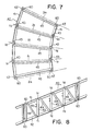
- the angles at which the truss members 41 and 42 are folded are such that the straight sections of the chord truss members 41 and 42 extend substantially along the arcs having centers O 1 to 0 5 and radii R, to R 5 as shown in Fig. 3. Since the chord members 41 and 42 are folded as described above, the vertical members 43 can be easily secured at the folded points b, to b 3 and c, to C3 as shown in Figs. 7 to 9.
- cross members 45 on which the rails are secured are mounted on the vertical members 43, these cross members 45 are automatically positioned in parallel to straight lines I,, 1 2 , and 1 3 passing through the outer and inner folding points b 1 ⁇ b 1 , b 2 -b 2 , and b 3 -b 3 as shown in Fig. 7.
- the vertical truss members are disposed at the folding points in the upper and the lower chord truss members of the truss units, and since the vertical members are aligned on the lines passing through the center of curvature of the escalator, the cross members for supporting the guide rails are positioned in parallel to the straight lines passing through the center of curvature. Therefore, the positioning of the guide rails can be easily and accurately achieved by utilizing any of the positions along the vertical truss members as a reference point for positioning the guide rails, thereby facilitating the positioning of the guide rails.
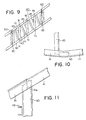
- the folding points b 1 ⁇ C 1 , b 2 -c 2 , and b 3 -c 3 shown in Figs. 8 and 9 may be vertical cut portions cut along vertical lines rather than the vertical folded portions.
- the vertical cut portions do not have to extend along vertical straight lines but may be sufficient when the positions at which the ends of the vertical truss members 43 fall on vertical straight lines.
- Figs. 10 and 11 illustrate in enlarged plan and side views a vertical folded portion or a vertical cut portion of a chord truss member 41.
- the upper end of the vertical truss member 43 is rigidly secured to the upper chord member 41 with reference to the vertical folded portion or the vertical cut portion 41 a, and the lower end of the vertical truss member 43 is similarly secured to the lower chord truss member 42 at the position of the vertical folded or cut portion.
- the vertical truss members 43 can be positioned with the vertical folded or cut portions of the upper and lower chord truss members used as positioning reference points, the positioning and assembly of the vertical truss members 43 is easy and the positioning and the assembly of the cross members 45 secured to the vertical members 43 are also facilitated.
- FIG. 7 since vertical members 43' are disposed at the opposite circumferential ends of truss units 40a, these vertical truss members 43' are also automatically positioned on a diameter passing through one of the centers of curvature O 1 to O s previously described when the vertical members 43' are secured at the ends of the folded chord truss members as described previously. Therefore, the cross truss members 45 extending between the vertical members 43' are also placed in parallel with lines I m passing through one of the centers of curvature O 1 or 0 5 .
- a connecting piece 60 is provided on each of the vertical truss members 43 for connecting the associated truss unit 40a to the adjacent truss units.
- the abutting surfaces of the connecting pieces 60 are arranged to be positioned on the same plane as a vertical plane passing through the line I m . This arrangement facilitates the connection between the adjacent truss units. While four connecting pieces 60 are provided in the vertical plane at the ends of the truss units 40a, any number of the connecting pieces 60 may be used. Also, the truss unit 40a itself may be a polygonal unit as illustrated or may be a straight unit. The connecting pieces 60 are placed in an abutting relationship with the mating connecting pieces 60 of the adjacent truss unit to be connected and may be secured by any securing means such as bolts and nuts.
Landscapes
- Escalators And Moving Walkways (AREA)
Claims (10)
Applications Claiming Priority (10)
| Application Number | Priority Date | Filing Date | Title |
|---|---|---|---|
| JP21183083A JPS60128185A (ja) | 1983-11-11 | 1983-11-11 | 曲線エスカレ−タの主枠 |
| JP211831/83 | 1983-11-11 | ||
| JP21182983A JPS60106784A (ja) | 1983-11-11 | 1983-11-11 | 曲線エスカレ−タの主枠 |
| JP211827/83 | 1983-11-11 | ||
| JP21182883A JPS60106783A (ja) | 1983-11-11 | 1983-11-11 | 曲線エスカレ−タの主枠 |
| JP21183183A JPS60106785A (ja) | 1983-11-11 | 1983-11-11 | 曲線エスカレータの主枠の組立方法 |
| JP21182783A JPS60106782A (ja) | 1983-11-11 | 1983-11-11 | 曲線エスカレ−タの主枠 |
| JP211828/83 | 1983-11-11 | ||
| JP211829/83 | 1983-11-11 | ||
| JP211830/83 | 1983-11-11 |
Publications (2)
| Publication Number | Publication Date |
|---|---|
| EP0142363A1 EP0142363A1 (fr) | 1985-05-22 |
| EP0142363B1 true EP0142363B1 (fr) | 1987-06-03 |
Family
ID=27529522
Family Applications (1)
| Application Number | Title | Priority Date | Filing Date |
|---|---|---|---|
| EP84307810A Expired EP0142363B1 (fr) | 1983-11-11 | 1984-11-12 | Charpente d'escalier roulant courbe |
Country Status (6)
| Country | Link |
|---|---|
| US (1) | US4726460A (fr) |
| EP (1) | EP0142363B1 (fr) |
| KR (1) | KR890003872Y1 (fr) |
| CA (1) | CA1224436A (fr) |
| DE (1) | DE3464047D1 (fr) |
| SG (1) | SG95487G (fr) |
Families Citing this family (12)
| Publication number | Priority date | Publication date | Assignee | Title |
|---|---|---|---|---|
| US4895239A (en) * | 1989-03-27 | 1990-01-23 | Otis Elevator Company | Curved escalator with fixed center constant radius path of travel |
| US4930622A (en) * | 1989-03-27 | 1990-06-05 | Otis Elevator Company | Curved escalator with fixed center constant radius path of travel |
| US5009302A (en) * | 1989-03-27 | 1991-04-23 | Otis Elevator Company | Curved escalator with fixed center constant radius path of travel |
| US4883160A (en) * | 1989-03-27 | 1989-11-28 | Otis Elevator Company | Curved escalator with fixed center constant radius path of travel |
| US4884673A (en) * | 1989-03-27 | 1989-12-05 | Otis Elevator Company | Curved escalator with fixed center constant radius path of travel |
| JPH03138293A (ja) * | 1989-03-30 | 1991-06-12 | Mitsubishi Electric Corp | 循環円形エスカレータ |
| US4953685A (en) * | 1989-08-10 | 1990-09-04 | Otis Elevator Company | Step chain for curved escalator |
| US4949832A (en) * | 1989-10-16 | 1990-08-21 | Otis Elevator Company | Curved escalator with vertical planar step risers and constant horizontal velocity |
| US5050721A (en) * | 1990-09-11 | 1991-09-24 | Otis Elevator Company | Step riser profile for curved escalator |
| DE4232113C2 (de) * | 1992-09-25 | 1995-11-23 | O & K Rolltreppen Gmbh | Bogenrolltreppe |
| ES2299408B1 (es) * | 2007-10-18 | 2009-06-12 | Thyssenkrupp Elevator (Es/Pbb) Ltd. | Sistema de guiado autoportante para pasillos rodantes. |
| CN104355213A (zh) * | 2014-11-06 | 2015-02-18 | 康力电梯股份有限公司 | 一种桁架加强装置 |
Family Cites Families (21)
| Publication number | Priority date | Publication date | Assignee | Title |
|---|---|---|---|---|
| US705794A (en) * | 1901-11-25 | 1902-07-29 | Harrison Snider | Winding staircase. |
| DE601565C (de) * | 1930-10-02 | 1934-08-18 | Carl Flohr A G | Wendeltreppe mit beweglichen Stufen |
| FR807933A (fr) * | 1936-05-25 | 1937-01-25 | Escalier mécanique | |
| US2633970A (en) * | 1951-01-18 | 1953-04-07 | Bell P Robinson | Produce-handling apparatus |
| US2695094A (en) * | 1952-12-26 | 1954-11-23 | Richard C Riley | Ascending and descending endless escalator |
| US2793738A (en) * | 1953-11-27 | 1957-05-28 | Lewis C Erickson | Knock-down conveyor gallery |
| US2823785A (en) * | 1954-01-13 | 1958-02-18 | Hefti Martin | Escalator adapted to follow a curved path |
| GB836292A (en) * | 1957-05-24 | 1960-06-01 | Rheinstahl Hamburg Stahlbau Eg | Improvements in moving staircases |
| FR1200297A (fr) * | 1957-05-24 | 1959-12-21 | Rheinstahl Hamburg Stahlbau Eg | Charpente de support pour escaliers mécaniques ou tapis roulants |
| US3185108A (en) * | 1963-07-10 | 1965-05-25 | C F Butz Engineering | Pedestrian carrier |
| US3664487A (en) * | 1969-05-23 | 1972-05-23 | Carl H Ballenger | Endless helical conveyer and belt |
| US3707220A (en) * | 1970-11-23 | 1972-12-26 | Westinghouse Electric Corp | Modular passenger conveyor construction |
| JPS4825559A (fr) * | 1971-08-03 | 1973-04-03 | ||
| US3857476A (en) * | 1973-01-29 | 1974-12-31 | Theodore Equipment Corp | Helical endless-belt mechanisms for fuel or empty distray transporting and lifting |
| US4064986A (en) * | 1976-04-30 | 1977-12-27 | Westinghouse Electric Corporation | Escalator having guide wheels and guide track with cooperative non-flat surfaces |
| CH621991A5 (fr) * | 1977-09-14 | 1981-03-13 | Oerlikon Buehrle Ag | |
| US4259825A (en) * | 1979-02-23 | 1981-04-07 | Nasa | Foldable beam |
| JPS5895965U (ja) * | 1981-12-21 | 1983-06-29 | 三菱電機株式会社 | 乗客コンベヤの主枠装置 |
| US4475323A (en) * | 1982-04-30 | 1984-10-09 | Martin Marietta Corporation | Box truss hoop |
| CA1204696A (fr) * | 1982-09-14 | 1986-05-20 | Hiroshi Nakatani | Escalier mecanique en colimacon |
| US4549634A (en) * | 1983-04-15 | 1985-10-29 | Waco International Corporation | Scaffold connector assembly |
-
1984
- 1984-10-10 KR KR2019840009919U patent/KR890003872Y1/ko not_active Expired
- 1984-11-07 CA CA000467242A patent/CA1224436A/fr not_active Expired
- 1984-11-12 EP EP84307810A patent/EP0142363B1/fr not_active Expired
- 1984-11-12 DE DE8484307810T patent/DE3464047D1/de not_active Expired
-
1986
- 1986-10-07 US US06/915,865 patent/US4726460A/en not_active Expired - Fee Related
-
1987
- 1987-10-29 SG SG954/87A patent/SG95487G/en unknown
Also Published As
| Publication number | Publication date |
|---|---|
| SG95487G (en) | 1988-05-06 |
| EP0142363A1 (fr) | 1985-05-22 |
| DE3464047D1 (en) | 1987-07-09 |
| CA1224436A (fr) | 1987-07-21 |
| KR890003872Y1 (ko) | 1989-06-08 |
| US4726460A (en) | 1988-02-23 |
| KR850009583U (ko) | 1985-12-05 |
Similar Documents
| Publication | Publication Date | Title |
|---|---|---|
| EP0142363B1 (fr) | Charpente d'escalier roulant courbe | |
| US4662502A (en) | Curved escalator | |
| US3707220A (en) | Modular passenger conveyor construction | |
| CA1204696A (fr) | Escalier mecanique en colimacon | |
| US9676597B2 (en) | Truss construction for a passenger conveyor | |
| EP0390630B1 (fr) | Trajet de marche d'un escalier roulant curviligne à centre fixé et au rayon constant | |
| EP0390629B1 (fr) | Trajet de marche d'un escalier roulant curviligne à centre fixé et au rayon constant | |
| CN100379676C (zh) | 无脉动的自动扶梯系统 | |
| EP0390632B1 (fr) | Trajet de marche d'un escalier roulant curviligne à centre fixé et au rayon constant | |
| US4235326A (en) | Main frame construction of conveyor | |
| EP0424209B1 (fr) | Escalier roulant avec des hauteurs de marches verticales planaires et avec vitesse costante horizontale | |
| US5170875A (en) | Conveyor machine | |
| US5009302A (en) | Curved escalator with fixed center constant radius path of travel | |
| JPS5924067B2 (ja) | エスカレ−タ | |
| US5544729A (en) | Curved escalator | |
| US10647549B2 (en) | Chain drive for a people conveyor | |
| CA1107222A (fr) | Escalier mobile | |
| JPS6036280A (ja) | コンベア・ベルト | |
| JPS6411554B2 (fr) | ||
| US1130555A (en) | Moving stairway. | |
| JPS6364387B2 (fr) | ||
| JPH05311B2 (fr) | ||
| JPS6411555B2 (fr) | ||
| JPH0485286A (ja) | マンコンベア | |
| JPH04345491A (ja) | 乗客コンベアの主枠 |
Legal Events
| Date | Code | Title | Description |
|---|---|---|---|
| PUAI | Public reference made under article 153(3) epc to a published international application that has entered the european phase |
Free format text: ORIGINAL CODE: 0009012 |
|
| AK | Designated contracting states |
Designated state(s): DE FR GB |
|
| 17P | Request for examination filed |
Effective date: 19851028 |
|
| 17Q | First examination report despatched |
Effective date: 19860902 |
|
| GRAA | (expected) grant |
Free format text: ORIGINAL CODE: 0009210 |
|
| AK | Designated contracting states |
Kind code of ref document: B1 Designated state(s): DE FR GB |
|
| REF | Corresponds to: |
Ref document number: 3464047 Country of ref document: DE Date of ref document: 19870709 |
|
| ET | Fr: translation filed | ||
| PLBE | No opposition filed within time limit |
Free format text: ORIGINAL CODE: 0009261 |
|
| STAA | Information on the status of an ep patent application or granted ep patent |
Free format text: STATUS: NO OPPOSITION FILED WITHIN TIME LIMIT |
|
| 26N | No opposition filed | ||
| REG | Reference to a national code |
Ref country code: GB Ref legal event code: 746 Effective date: 19951026 |
|
| REG | Reference to a national code |
Ref country code: FR Ref legal event code: D6 |
|
| PGFP | Annual fee paid to national office [announced via postgrant information from national office to epo] |
Ref country code: FR Payment date: 19981110 Year of fee payment: 15 |
|
| PGFP | Annual fee paid to national office [announced via postgrant information from national office to epo] |
Ref country code: GB Payment date: 19981113 Year of fee payment: 15 |
|
| PGFP | Annual fee paid to national office [announced via postgrant information from national office to epo] |
Ref country code: DE Payment date: 19981120 Year of fee payment: 15 |
|
| PG25 | Lapsed in a contracting state [announced via postgrant information from national office to epo] |
Ref country code: GB Free format text: LAPSE BECAUSE OF NON-PAYMENT OF DUE FEES Effective date: 19991112 |
|
| GBPC | Gb: european patent ceased through non-payment of renewal fee |
Effective date: 19991112 |
|
| PG25 | Lapsed in a contracting state [announced via postgrant information from national office to epo] |
Ref country code: FR Free format text: LAPSE BECAUSE OF NON-PAYMENT OF DUE FEES Effective date: 20000731 |
|
| PG25 | Lapsed in a contracting state [announced via postgrant information from national office to epo] |
Ref country code: DE Free format text: LAPSE BECAUSE OF NON-PAYMENT OF DUE FEES Effective date: 20000901 |
|
| REG | Reference to a national code |
Ref country code: FR Ref legal event code: ST |