EP0143278A1 - Appareil pour produire des tuyaux en matière plastique - Google Patents
Appareil pour produire des tuyaux en matière plastique Download PDFInfo
- Publication number
- EP0143278A1 EP0143278A1 EP84111835A EP84111835A EP0143278A1 EP 0143278 A1 EP0143278 A1 EP 0143278A1 EP 84111835 A EP84111835 A EP 84111835A EP 84111835 A EP84111835 A EP 84111835A EP 0143278 A1 EP0143278 A1 EP 0143278A1
- Authority
- EP
- European Patent Office
- Prior art keywords
- die
- channels
- die halves
- sequences
- frame
- Prior art date
- Legal status (The legal status is an assumption and is not a legal conclusion. Google has not performed a legal analysis and makes no representation as to the accuracy of the status listed.)
- Granted
Links
- 238000000465 moulding Methods 0.000 claims abstract description 15
- 238000001125 extrusion Methods 0.000 claims description 15
- 239000011159 matrix material Substances 0.000 claims description 4
- 238000001816 cooling Methods 0.000 claims 2
- 238000007493 shaping process Methods 0.000 claims 1
- 238000004519 manufacturing process Methods 0.000 description 13
- 238000000034 method Methods 0.000 description 2
- 230000006978 adaptation Effects 0.000 description 1
- 239000000969 carrier Substances 0.000 description 1
- 238000006243 chemical reaction Methods 0.000 description 1
- 230000007704 transition Effects 0.000 description 1
Images

Classifications
-
- B—PERFORMING OPERATIONS; TRANSPORTING
- B29—WORKING OF PLASTICS; WORKING OF SUBSTANCES IN A PLASTIC STATE IN GENERAL
- B29C—SHAPING OR JOINING OF PLASTICS; SHAPING OF MATERIAL IN A PLASTIC STATE, NOT OTHERWISE PROVIDED FOR; AFTER-TREATMENT OF THE SHAPED PRODUCTS, e.g. REPAIRING
- B29C49/00—Blow-moulding, i.e. blowing a preform or parison to a desired shape within a mould; Apparatus therefor
- B29C49/0015—Making articles of indefinite length, e.g. corrugated tubes
- B29C49/0021—Making articles of indefinite length, e.g. corrugated tubes using moulds or mould parts movable in a closed path, e.g. mounted on movable endless supports
-
- B—PERFORMING OPERATIONS; TRANSPORTING
- B29—WORKING OF PLASTICS; WORKING OF SUBSTANCES IN A PLASTIC STATE IN GENERAL
- B29C—SHAPING OR JOINING OF PLASTICS; SHAPING OF MATERIAL IN A PLASTIC STATE, NOT OTHERWISE PROVIDED FOR; AFTER-TREATMENT OF THE SHAPED PRODUCTS, e.g. REPAIRING
- B29C2791/00—Shaping characteristics in general
- B29C2791/004—Shaping under special conditions
- B29C2791/006—Using vacuum
-
- B—PERFORMING OPERATIONS; TRANSPORTING
- B29—WORKING OF PLASTICS; WORKING OF SUBSTANCES IN A PLASTIC STATE IN GENERAL
- B29C—SHAPING OR JOINING OF PLASTICS; SHAPING OF MATERIAL IN A PLASTIC STATE, NOT OTHERWISE PROVIDED FOR; AFTER-TREATMENT OF THE SHAPED PRODUCTS, e.g. REPAIRING
- B29C33/00—Moulds or cores; Details thereof or accessories therefor
- B29C33/0022—Multi-cavity moulds
-
- B—PERFORMING OPERATIONS; TRANSPORTING
- B29—WORKING OF PLASTICS; WORKING OF SUBSTANCES IN A PLASTIC STATE IN GENERAL
- B29L—INDEXING SCHEME ASSOCIATED WITH SUBCLASS B29C, RELATING TO PARTICULAR ARTICLES
- B29L2023/00—Tubular articles
- B29L2023/18—Pleated or corrugated hoses
Definitions
- the invention relates to a device for producing plastic pipes according to the preamble of claim 1.
- two sequences of die halves each rotating in an endless path.
- the webs adjoin one another along a working path in such a way that the die halves of the two webs lying opposite one another each form a continuous hollow shape for such a tube.
- the still plastic tube is extruded into this continuous hollow shape and, by creating a pressure gradient between the inside of the tube and the outside thereof, is molded onto the die walls. This tube moves together with the two sequences of dies until it has cooled sufficiently and is thus solidified and the two sequences of matrices diverge again when the endless path is covered.
- the die halves are provided with several mutually parallel, different shaped channels. These die halves can be moved transversely to the longitudinal direction of a chain carrying them. Control slides for the shifting position run around in guide rails which are provided with switches. It is thus possible with the known device to switch from one form of the tube just produced to another by controlling the complicated switch arrangement in the ongoing extrusion process. It is thus possible with the known device to continuously produce pipes with differently shaped sections by extrusion.
- the invention provides a device which enables the production changeover from one form of an endless tube to another, in particular from a cross-section to a larger or smaller one, with only little constructional expenditure, without the die halves needing to be replaced.
- the individual, separate die halves are not moved in their relative position to a chain carrying them, which in turn rotates stationary with respect to the extrusion die, but the guide means can assume such different positions relative to the extrusion die with frame and drive that in each case the desired molding channel of the die halves forming a plurality of molding channels lies in front of the extrusion die.
- This seemingly complex route is surprisingly easier than training according to the state of the art.
- the device according to the invention allows the rapid changeover of production from the production of an endless tube with one shape (wall profile, diameter and the like) to an endless tube with a different shape, without the structural complexity of the latter, therefore, only for the production of a single one In the form of an endless tube suitable device would need to be significantly exceeded.
- the manufacture of a device which, according to the invention, has die halves with, for example, three mold cavities is considerably cheaper than the manufacture of the latter known device with three sets of different die halves.
- the device according to the invention is not subject to such restrictions, since the one carrying the guide means
- the frame can be adjusted in practically any position by means of a suitable adjusting device without further ado and with little mechanical effort.
- the conversion of the manufacturing process is further simplified and facilitated by the fact that an end stop is assigned to each of the mold channels formed by the die sequences, which is attached to the frame or to the stationary base frame carrying it and allows each the positions of the frame can be approached easily and without additional adjustment work.
- the changeover of the manufacturing process is not only particularly quick, but can be done by inexperienced personnel without white teres.
- the exchange dies can have the same or a different number of mold channels than the die halves originally provided.
- end stops are themselves adjustable, so that adaptation to the die halves used is possible.
- the number of form channels in the matrix sequences can be selected within wide limits, especially when a guide channel is used as the guide means that is suitable for guiding even very high die halves cleanly. In view of the effort required to cool the die half, die halves with two to five mold channels are particularly preferred.
- the frame carrying the guide means is adjusted by a drive by means of a plug-in hexagon key.
- a power drive for adjusting the positions of the guide provided means or the frame whereby the changeover work is simplified and accelerated.
- This power drive can take place, for example, by means of a pneumatic or hydraulic lifting cylinder which acts on the frame guided in the adjustment direction.
- the end stops can be replaced by readable markings or a suitable coding in a drive control unit.
- the end stops are preferably coupled to the power drive in such a way that they automatically switch off the power drive when a desired position is reached.
- Microswitches are particularly suitable here, which stop the lifting motor when passing a stop that is movable relative to them.
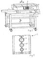
- Fig. 1 the overall arrangement of an embodiment of the device according to the invention is shown schematically.
- a base 7 rests on a fixed base 9 perpendicular to the circumferential plane of the die halves, i.e. here in the vertical direction along the double arrow B, of which for the sake of simplicity only two supports, each forming a longitudinal rail, are shown, which are connected by cross members (in FIG. 3 shown) are interconnected.
- This underframe is attached by means of a (not shown) e.g. known drive moves up and down in the vertical direction and can be determined in preselected heights or positions.
- a (not shown) e.g. known drive moves up and down in the vertical direction and can be determined in preselected heights or positions.
- a frame 3 On the top of the carrier runs a frame 3, which is also essentially horizontally aligned and which is supported on the carriers via rollers 11. This arrangement of the mold, which can be moved in the extrusion direction, is known and generally customary and is therefore not explained in detail.
- On the The top of this carrier 3 rests two elongated oval guide channels 2, in each of which a matrix sequence of matrix halves 1 rotates in the usual manner.
- Each of these die halves 1 has a plurality of mold half-channels 4, 5 and 6 which are arranged next to one another and differ from one another, preferably of different sizes.
- a (not shown) drive allows the die halves 1 to rotate in opposite directions in the two adjacent guide channels 2, the individual die halves 1 being placed in the middle region of the frame to form a plurality of hollow shapes, as can be seen from FIG. 2, through the guide channels 2.
- a still-formable, under-calibrated tube is introduced from an extruder head (not shown) into a continuous molding channel formed along the above-mentioned route and occurs solidified at the end of this channel and in accordance with the wall configuration of the channel shaped out again.
- the extruder head In a position which is stationary relative to the base 9 is the extruder head (not shown) with an extruder nozzle which ejects a still deformable hose coaxially with the migrating mold channel located in front of it and introduces it into it.
- the extruder head is always easily accessible by pushing the frame 3 away.
- the extrusion is stopped in the usual way and the base frame 7 and thus the frame 3 and the die halves 1 are raised or lowered in the direction of arrow B until the molding channel corresponding to the desired product lies coaxially with the extruder head in front of it. Then the extruder is started up again in the usual way.
- the base frame 7 is shown in more detail in FIG. 3; as can be seen, the two longitudinal beams are connected to one another by cross members.
- the two worm shafts 14 are extended at one end and each provided with a sprocket 15, both of which are connected by a chain 16.
- One of the worm spindles 14 is extended beyond the sprocket 15 and carries a drive motor 17, which in turn is seated firmly on the base 9.
- the gear or thread pairings on the two sides of the underframe 7 are coordinated with one another in such a way that when the motor rotates, the underframe 7 is raised or lowered evenly, that is to say always in a horizontal position.
- the nuts or worm wheels 13 are in turn mounted in the base 9 in such a way that they cannot move up and down.
- a protruding stop 18 is attached, which is designed to be arranged opposite and above one another on the base 9 croswitch (not shown) to engage so that the drive motor 17 connected via the microswitch comes to a standstill whenever the stopper 18 engages with one of the microswitches.
- the position of the microswitch can be adjusted independently of one another in the vertical direction, so that the approach height of each molding channel 4, 5, 6 can be set exactly to the height of the extruder head by adjusting the corresponding microswitch.
Landscapes
- Engineering & Computer Science (AREA)
- Manufacturing & Machinery (AREA)
- Mechanical Engineering (AREA)
- Extrusion Moulding Of Plastics Or The Like (AREA)
- Blow-Moulding Or Thermoforming Of Plastics Or The Like (AREA)
Applications Claiming Priority (2)
| Application Number | Priority Date | Filing Date | Title |
|---|---|---|---|
| DE3335850 | 1983-10-03 | ||
| DE3335850A DE3335850C2 (de) | 1983-10-03 | 1983-10-03 | Vorrichtung zum Herstellen von Kunststoffrohren |
Publications (2)
| Publication Number | Publication Date |
|---|---|
| EP0143278A1 true EP0143278A1 (fr) | 1985-06-05 |
| EP0143278B1 EP0143278B1 (fr) | 1988-04-13 |
Family
ID=6210797
Family Applications (1)
| Application Number | Title | Priority Date | Filing Date |
|---|---|---|---|
| EP84111835A Expired EP0143278B1 (fr) | 1983-10-03 | 1984-10-03 | Appareil pour produire des tuyaux en matière plastique |
Country Status (5)
| Country | Link |
|---|---|
| US (1) | US4674969A (fr) |
| EP (1) | EP0143278B1 (fr) |
| JP (1) | JPS61500657A (fr) |
| DE (1) | DE3335850C2 (fr) |
| WO (1) | WO1985001471A1 (fr) |
Cited By (4)
| Publication number | Priority date | Publication date | Assignee | Title |
|---|---|---|---|---|
| GB2240302A (en) * | 1989-12-29 | 1991-07-31 | Kenneth Macmillan | Moulding articles of different length or diameter in a single mould |
| WO1993025373A1 (fr) * | 1992-06-15 | 1993-12-23 | Lupke Manfred Arno Alfred | Moule mobile de moulage a cavites multiples pour le moulage de tubes profiles et blocs de moulage |
| US5433916A (en) * | 1993-06-18 | 1995-07-18 | Dowbrands, Inc. | Utilizing multi cavity mold in extrusion blow molding process |
| DE10058889A1 (de) * | 2000-11-24 | 2002-06-06 | Binder Gottlieb Gmbh & Co | Verfahren zum Herstellen von Profilen |
Families Citing this family (14)
| Publication number | Priority date | Publication date | Assignee | Title |
|---|---|---|---|---|
| DE3930318C1 (fr) * | 1989-09-11 | 1990-05-17 | Fraenkische Rohrwerke Gebr. Kirchner Gmbh & Co, 8729 Koenigsberg, De | |
| DE4004282C1 (en) * | 1990-02-13 | 1991-05-16 | Unicor Gmbh Rahn Plastmaschinen, 8728 Hassfurt, De | Appts. for plastic pipe prodn. - comprises injection head with nozzle unit and moulding unit having two matrix sections |
| DE4200628C1 (en) * | 1992-01-13 | 1993-06-17 | Fraenkische Rohrwerke Gebr. Kirchner Gmbh & Co, 8729 Koenigsberg, De | Extruder head with e.g. three settings - has die and intermediate feed tool which can both be rotated to align their angled flow bores differently with that supplied from extruder |
| CA2077872C (fr) * | 1993-12-20 | 1998-06-09 | Manfred A. A. Lupke | Installation pour la fabrication de tuyaux en plastique a ondulations annulaires et methode de fabrication de ceux-ci |
| DE69601509T2 (de) * | 1995-03-28 | 1999-06-17 | Corelco, Manziat | Vakuumzuführkreislauf für eine Anlage zum Herstellen von Wellenrohren |
| DE19517023C1 (de) * | 1995-05-10 | 1996-06-13 | Unicor Rohrsysteme Gmbh | Vorrichtung zum Herstellen von Rohren mit Querrippen |
| DE29814457U1 (de) * | 1997-10-03 | 1998-12-24 | Lupke, Manfred Arno Alfred, Thornhill, Ontario | Vorrichtung zum Formen von Kunststoffteilen |
| DE19845321C2 (de) * | 1998-10-01 | 2002-03-28 | Unitec Gmbh Tech Entwicklungen | Vorrichtung zur Herstellung von dünnwandigen glatten Kunststoffrohren mit gewellten Sektionen in unterschiedlichen Abständen zueinander |
| DE10348242B4 (de) * | 2003-10-16 | 2006-11-30 | Thyssen Polymer Gmbh | Schnellrüstsystem für Kalibriervorrichtungen |
| DE102007049653A1 (de) * | 2007-10-12 | 2009-04-16 | Unicor Gmbh | Vorrichtung zum Herstellen von thermoplastischen Wellrohren |
| DE202008005870U1 (de) | 2008-04-28 | 2008-10-23 | Maintools Gmbh & Co.Kg | Formvorrichtung, insbesondere Corrugator, zum Herstellen von profilierten Kunststoffrohren |
| JP6131094B2 (ja) * | 2013-05-09 | 2017-05-17 | 矢崎総業株式会社 | コルゲートチューブ製造装置及びコルゲートチューブ製造方法 |
| CN103419350B (zh) * | 2013-08-27 | 2016-08-10 | 青州市塑霸机械有限公司 | 一种连续循环运转的塑料管材模具冷却装置 |
| DE102013015306A1 (de) * | 2013-09-14 | 2015-03-19 | G & S Plast GmbH & Co. KG | Multichannel - Corrugator zur Herstellung von flexiblen Wellrohren, mit modularem Aufbau und mit parallel angeordneten und mit mindestens drei horizontal nebeneinander liegenden Formkanäle. |
Citations (2)
| Publication number | Priority date | Publication date | Assignee | Title |
|---|---|---|---|---|
| DE1116180B (de) * | 1959-07-08 | 1961-11-02 | Mannesmann Meer Ag | Metallstrangpresse |
| EP0048113A1 (fr) * | 1980-09-12 | 1982-03-24 | Manfred Arno Alfred Lupke | Dispositif et procédé pour fabriquer des tubes en matière thermoplastique |
Family Cites Families (16)
| Publication number | Priority date | Publication date | Assignee | Title |
|---|---|---|---|---|
| US2281860A (en) * | 1939-05-27 | 1942-05-05 | Jean C Renault | Continuous feed and pressure press |
| US2613619A (en) * | 1947-02-01 | 1952-10-14 | Adolf E Willomitzer | Multiple mold continuous plastic forming machine |
| US2866230A (en) * | 1956-02-24 | 1958-12-30 | Pullman Vacuum Cleaner Corp | Corrugated rubber tubing and its production |
| NL124750C (fr) * | 1959-02-21 | 1900-01-01 | ||
| DE1218574B (de) * | 1961-10-19 | 1966-06-08 | Wilhelm Hegler | Kunststoffrohr fuer Elektroinstallation |
| US3286430A (en) * | 1963-02-11 | 1966-11-22 | Joseph J Esty | Method of sealing and packaging |
| GB1193939A (en) * | 1967-11-29 | 1970-06-03 | Wilhelm Hegler | Apparatus for and a Method of Producing Plastics Pipes |
| DE2061027C3 (de) * | 1970-12-11 | 1982-03-04 | Wilhelm 8730 Bad Kissingen Hegler | Vorrichtung zum Anbringen einer Querprofilierung an einem Rohr aus thermoplastischem Kunststoff |
| US3746487A (en) * | 1971-08-23 | 1973-07-17 | Armstrong Cork Co | Conveyor-mold construction |
| US3981663A (en) * | 1973-09-10 | 1976-09-21 | Lupke Gerd Paul Heinrich | Apparatus for making high speed corrugated plastic tubing |
| US4003685A (en) * | 1974-10-09 | 1977-01-18 | Maroschak Ernest J | Apparatus for molding plastic pipe with enlarged portions formed therein |
| DE2537184C2 (de) * | 1975-08-21 | 1984-06-07 | Ziegelwerke Heinrich Oltmanns, 2905 Edewecht | Anlage zur kontinuierlichen Herstellung von Kunststoffrohren |
| MX144554A (es) * | 1976-07-30 | 1981-10-26 | Pont A Mousson | Mejoras a procedimiento y sistema para modificar el espesor de un cuerpo extruido a caudal constante |
| DE2832350A1 (de) * | 1978-07-22 | 1980-01-31 | Wilhelm Hegler | Vorrichtung zur herstellung von rohren aus thermoplastischem kunststoff mit querprofilierung |
| US4313750A (en) * | 1980-09-12 | 1982-02-02 | Css International Corporation | Electronically controlled robot for handling glassware |
| DE3118932C3 (de) * | 1981-05-13 | 1995-02-09 | Wilhelm Hegler | Vorrichtung zur Herstellung von Kunststoffrohren mit Querrillen |
-
1983
- 1983-10-03 DE DE3335850A patent/DE3335850C2/de not_active Expired
-
1984
- 1984-10-03 US US06/741,668 patent/US4674969A/en not_active Expired - Lifetime
- 1984-10-03 EP EP84111835A patent/EP0143278B1/fr not_active Expired
- 1984-10-03 JP JP59503875A patent/JPS61500657A/ja active Pending
- 1984-10-03 WO PCT/DE1984/000206 patent/WO1985001471A1/fr not_active Ceased
Patent Citations (2)
| Publication number | Priority date | Publication date | Assignee | Title |
|---|---|---|---|---|
| DE1116180B (de) * | 1959-07-08 | 1961-11-02 | Mannesmann Meer Ag | Metallstrangpresse |
| EP0048113A1 (fr) * | 1980-09-12 | 1982-03-24 | Manfred Arno Alfred Lupke | Dispositif et procédé pour fabriquer des tubes en matière thermoplastique |
Cited By (7)
| Publication number | Priority date | Publication date | Assignee | Title |
|---|---|---|---|---|
| GB2240302A (en) * | 1989-12-29 | 1991-07-31 | Kenneth Macmillan | Moulding articles of different length or diameter in a single mould |
| GB2240302B (en) * | 1989-12-29 | 1993-09-15 | Kenneth Macmillan | Apparatus for and method of molding articles |
| WO1993025373A1 (fr) * | 1992-06-15 | 1993-12-23 | Lupke Manfred Arno Alfred | Moule mobile de moulage a cavites multiples pour le moulage de tubes profiles et blocs de moulage |
| US5433916A (en) * | 1993-06-18 | 1995-07-18 | Dowbrands, Inc. | Utilizing multi cavity mold in extrusion blow molding process |
| US5551860A (en) * | 1993-06-18 | 1996-09-03 | Dow Brands L.P. | Quick bottle production changeover utilizing multi-cavity molds in an extrusion blow molding system |
| US5556648A (en) * | 1993-06-18 | 1996-09-17 | Dowbrands Inc. | Quick bottle production changeover utilizing multi-cavity molds in an extrusion blow molding system |
| DE10058889A1 (de) * | 2000-11-24 | 2002-06-06 | Binder Gottlieb Gmbh & Co | Verfahren zum Herstellen von Profilen |
Also Published As
| Publication number | Publication date |
|---|---|
| JPS61500657A (ja) | 1986-04-10 |
| US4674969A (en) | 1987-06-23 |
| WO1985001471A1 (fr) | 1985-04-11 |
| EP0143278B1 (fr) | 1988-04-13 |
| DE3335850C2 (de) | 1986-11-06 |
| DE3335850A1 (de) | 1985-04-18 |
Similar Documents
| Publication | Publication Date | Title |
|---|---|---|
| EP0143278B1 (fr) | Appareil pour produire des tuyaux en matière plastique | |
| DE69517467T2 (de) | Kombinierte Formträger und Gestängevorrichtung | |
| EP0363394B1 (fr) | Unite de fixation de precision pour machines de moulage par injection | |
| DE19747698C2 (de) | Blasformmaschine | |
| EP1673208B1 (fr) | Machine de moulage par injection horizontale pourvue d'un dispositif tournant | |
| DE1479679B2 (de) | Vorrichtung zum Herstellen von Fla sehen aus thermoplastischem Kunststoff | |
| EP2200804B1 (fr) | Dispositif pour fabriquer des tubes ondulés thermoplastiques | |
| EP0623449B1 (fr) | Cadre de fixation pour une machine d'emboutissage | |
| EP0641279A1 (fr) | Machine a souffler. | |
| DE2442676A1 (de) | Biegevorrichtung fuer maschinen zur herstellung geschweisster rohre | |
| EP0155332A1 (fr) | Support intermédiaire de pièce dans une presse-transfert | |
| DE2429223A1 (de) | Kontinuierlich arbeitende rotationsvorrichtung zum formblasen von kunststoffhohlkoerpern | |
| EP0585664A1 (fr) | Machine à mouler par injection des matières plastiques | |
| EP0116132A1 (fr) | Presse à mouler par injection ainsi que procédé pour fabriquer des pièces moulées par injection | |
| DE1604575C3 (de) | Vorrichtung zum Herstellen von Hohl-' körpern aus thermoplastischem Kunststoff im Blasverfahren | |
| DE4223314A1 (de) | Einrichtung zum Schließen und Öffnen von Formen | |
| DE2656218C2 (de) | Form- und Packmaschine | |
| EP1053857B1 (fr) | Machine à souffler pour soufflage avec bavures réduites | |
| DE1920920A1 (de) | Maschine zum Herstellen von Giessereiformen aus Formsand | |
| DE2528645C3 (de) | Vorrichtung zur automatischen Herstellung kastenloser Gießformen | |
| DE3201447C1 (de) | Vorrichtung zum Wechseln von Modellplatten in Formmaschinen | |
| DE3542878A1 (de) | Auswerfereinrichtung fuer spritzgiessmaschinen | |
| DE420318C (de) | Graviermaschine | |
| DE2255536C3 (de) | Maschine zum Herstellen geblasener Hohlkörper aus thermoplastischem Kunststoff | |
| DE2461214A1 (de) | Vorrichtung zum herstellen von kunststoffrohren |
Legal Events
| Date | Code | Title | Description |
|---|---|---|---|
| PUAI | Public reference made under article 153(3) epc to a published international application that has entered the european phase |
Free format text: ORIGINAL CODE: 0009012 |
|
| AK | Designated contracting states |
Designated state(s): FR IT |
|
| 17P | Request for examination filed |
Effective date: 19851121 |
|
| ITCL | It: translation for ep claims filed |
Representative=s name: BARZANO' E ZANARDO MILANO S.P.A. |
|
| EL | Fr: translation of claims filed | ||
| 17Q | First examination report despatched |
Effective date: 19860813 |
|
| ITF | It: translation for a ep patent filed | ||
| GRAA | (expected) grant |
Free format text: ORIGINAL CODE: 0009210 |
|
| AK | Designated contracting states |
Kind code of ref document: B1 Designated state(s): FR IT |
|
| ET | Fr: translation filed | ||
| PLBI | Opposition filed |
Free format text: ORIGINAL CODE: 0009260 |
|
| 26 | Opposition filed |
Opponent name: HEGLER PLASTIK GMBH Effective date: 19890111 Opponent name: CORMA INC. Effective date: 19890109 |
|
| PGFP | Annual fee paid to national office [announced via postgrant information from national office to epo] |
Ref country code: FR Payment date: 19911017 Year of fee payment: 8 |
|
| ITTA | It: last paid annual fee | ||
| RDAG | Patent revoked |
Free format text: ORIGINAL CODE: 0009271 |
|
| STAA | Information on the status of an ep patent application or granted ep patent |
Free format text: STATUS: PATENT REVOKED |
|
| 27W | Patent revoked |
Effective date: 19920120 |
|
| APAH | Appeal reference modified |
Free format text: ORIGINAL CODE: EPIDOSCREFNO |