EP0143543B1 - Dispositif de découpe - Google Patents
Dispositif de découpe Download PDFInfo
- Publication number
- EP0143543B1 EP0143543B1 EP84307261A EP84307261A EP0143543B1 EP 0143543 B1 EP0143543 B1 EP 0143543B1 EP 84307261 A EP84307261 A EP 84307261A EP 84307261 A EP84307261 A EP 84307261A EP 0143543 B1 EP0143543 B1 EP 0143543B1
- Authority
- EP
- European Patent Office
- Prior art keywords
- cutters
- cutting device
- pivot pin
- blade edge
- edge portion
- Prior art date
- Legal status (The legal status is an assumption and is not a legal conclusion. Google has not performed a legal analysis and makes no representation as to the accuracy of the status listed.)
- Expired
Links
Images


Classifications
-
- B—PERFORMING OPERATIONS; TRANSPORTING
- B26—HAND CUTTING TOOLS; CUTTING; SEVERING
- B26B—HAND-HELD CUTTING TOOLS NOT OTHERWISE PROVIDED FOR
- B26B13/00—Hand shears; Scissors
- B26B13/04—Hand shears; Scissors with detachable blades
-
- B—PERFORMING OPERATIONS; TRANSPORTING
- B26—HAND CUTTING TOOLS; CUTTING; SEVERING
- B26B—HAND-HELD CUTTING TOOLS NOT OTHERWISE PROVIDED FOR
- B26B13/00—Hand shears; Scissors
- B26B13/28—Joints
Definitions
- This invention relates to cutting devices having pivoted cutters which operate with shear action.
- Cutting devices such as scissors and shears comprising a pair of blades which operate with a shear action about a pivot are well known. It is also well known to provide scissors in which cutters made of steel are secured to plastics handle portions.
- a cutting device having pivoted cutters which operate with a shear action
- which cutting device comprises a pair of cutters, a pair of handle portions one for each cutter of the pair, and a pivot pin means which enables the cutters to be mutually pivoted and held together, the cutters each having a blade body portion having a pivot pin hole therein for the pivot pin means and a blade edge portion which extends obliquely from the blade body portion longitudinally of the blade body portion from the end thereof remote from the handle portions to a region before the pivot pin hole.
- the cutters may be made of a metal and the handle portions may be made of a plastics material.
- the cutting device described in GB-A-610035 can snap across the pivot pin hole if too much pressure is applied to the handle portions. This is because the pivot pin hole extends through the handle portions and weakens the handle portions at this point. Handle portions made of steel could possibly tolerate this weakening. However handle portions made of a plastics material often cannot tolerate this weakening and one or other of the handle portions may often snap off if the handle portions are squeezed together too hard.
- this invention provides a cutting device having pivoted cutters which operate with a shear action, which cutting device comprises a pair of cutters, a pair of handle portions one for each cutter of the pair, and a pivot pin means which enables the cutters to be mutually pivoted and held together, the cutters each having a blade body portion having a pivot pin hole therein for the pivot means and a blade edge portion which is for effecting a cutting action, the cutters being made of a metal, and the handle portions being made of a plastics material which extends partially over the metal of the cutters, characterised in that the blade edge portion extends obliquely from the blade body portion from the end thereof remote from the handle portions to a region beyond the pivot pin hole.
- each blade edge portion extends to the region beyond the pivot pin hole, it is able to reinforce the cutting device and especially the handle portions in the region of the pivot pin hole and snapping of the handles, even under severe squeezing pressure, can be prevented.
- each cutter is provided with keying means for causing the cutter to key to the plastics material.
- the metal for the cutters will usually be steel and the keying means may be, for example, holes, slots, notches or projecting portions such as lugs.
- the blade edge portion extends along the blade body portion to beyond the pivot pin holes, the blade body portion is thereby strengthened and any risk of fracturing of the blade body portion in the region of the pivot pin hole is thereby substantially obviated.
- the blade edge portion may extend beyond that end of the blade body portion remote from the handle portions.
- the blade edge portion may be tapered so as to be thicker at the end remote from the handle portions. This facilitates a good cutting action.
- At least one of the cutters is bent towards the other. If desired, both cutters may be bent towards each other. This bending also facilitates a good cutting action.
- the bending may occur about a line near the pivot pin and on the cutter side of the pivot pin.
- the bending of the cutters may be regarded as preloading the cutters. As the cutters cross to cut, they can flex slightly against the preloading.
- one blade may be bent inwardly by Y4 inch (i.e. 6.25 millimetres), or both blades may be bent inwardly by % inch (i.e. 3.125 millimetres).
- the blade or blades are preferably bent inwardly by a press.
- the press may be a power press or a hand press.
- the blades may be bent inwardly by induction hardening.
- Each blade being bent is normally clamped around its pivot pin hole during the bending.
- the bending may be effected as a separate operation or as part of one of the other operations in the manufacture of the scissors.
- the blade edge portion and the blade body portion may be press formed from a steel blank.
- the blade edge portion may be hardened as by means of a laser hardening process or by means of an induction hardening process.
- the blade edges may be characterised by a Rock- wall hardness figure of the order of 56.
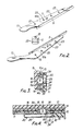
- a pair of scissors comprises a first member 2 and a second member 4 pivoted about a pin 6 which fits within a bush 6a.
- the member 2 comprises a moulded plastics handle 8 and a steel cutter 10.
- the member 4 comprises a moulded plastics handle 12 and a steel cutter 14.
- the handle 8 has a thumb hole 8a and the handle 12 has a finger hole 12a.
- the cutter 10 is embedded in plastics material 11 forming a part of the handle 8 and the cutter 10 is also provided with an extension piece 13 which extends into the handle 8 and around which the handle 8 is moulded.
- the cutter 14 is embedded in plastics material 15 and the cutter 14 is also provided with an extension piece 17 which extends into the handle 12 and around which the handle 12 is moulded.
- the cutter 10 is press formed from a steel blank and it has a flat blade body portion 3 from which a blade edge portion 5 is arranged to extend obliquely.
- the cutter 14 is similarly formed and fabricated, and it has a flat blade body portion 7 and a blade edge portion 9. Holes 19 and 21 are formed in the blade body portions 3 and 7 respectively to receive the pin 6 about which they are pivoted. Others holes 23 are formed in the blade body portions 3 and 7 to receive the plastics material 11 and so enable a good key to be provided between the cutters 10, 14 and their respective plastic handles 8, 12.
- the blade edge portions 5 and 9 are arranged to extend longitudinally of their respective blade body portions 3 and 7 to beyond the holes 19 and 21 whereby the regions of the blade body portions 3 and 7 around the holes 19 and 21 respectively, are strengthened.
- This extension of the blade edge portions 9 and 13 thus serve to strengthen the cutters 10 and 14 and to facilitate the provision of scissors suitable for rugged use.
- the blade edge portions 5 and 9 are tapered so that they are slightly thicker at their ends remote from the extension pieces 13 and 17 to improve end cutting action.
- the end cutting action is also improved by bending one or both of the entire cutters 10, 14 towards each other, for example about one or both of the crink lines 10a, 14a shown in Figure 2.
- the blade edge portions 5 and 9 are hardened as by laser hardening or induction hardening to give a Rockwell figure of about 56.
- the blade edge portions 5 and 9 cut well due the blade edge hardening but they tend to become slightly brittle.
- the brittleness does not matter however as the body portions 3 and 7 are not hardened so that the body portions 3 and 7 do not become brittle. Obviously, if brittleness is not a governing factor, then the entire cutters 10, 14 can be hardened.
- blade edge portions 5 and 9 of the cutters 10, 14 respectively extend proud of the plastics material (as shown in Figure 3) so that they can effect a cutting action.
- the diameter of one end portion of the pin 6 is reduced to define a spigot 16, the spigot 16 being peened or spun over to define an abutment part in the form of a rivet head 18.
- the rivet head 18 serves to secure the cutter 14 in position on the pin 6.
- the cutter 10 is held in position on the pin 6 by means of a slotted clip 20.
- the clip 20 is located in a circumferential groove 22 which is formed in the pin 6 at its other end portion.
- the clip 20 comprises a flat strip having a wider slotted end part 21 which includes an elongate slot 24 in which the pin 6 is accommodated.
- the slot 24 may either have an open end 26 as shown in Figure 6 or it may extend to define a circular aperture 28 as shown in Figure 5.
- the clip 20 may be made of a metal such for example as spring steel.
- the circular aperture 28 is placed over the pin 6 whereby the slotted end part 21 of the clip 20 can be slid on to the complementary groove 22 in the pin 6.
- the open end 26 facilitates positioning of the slotted end part 21 of the clip 20 in the groove 22 of the pin 6.
- the strip material which defines the clip 20 is bent back on itself to form a limb 29 which lies parallel with the slotted end part 21 of the clip 20 and which is further bent to define an end portion 30 which includes a projection 32.
- the handle 8 in which the cutter 10 is secured is provided with a pair of undercut grooves 34 in which the wider slotted end part 21 of the clip 20 is accommodated.
- the cutter 10 is provided with a recess 36 (see Figure 4) in which the projection 32 is received to lock the clip 20 in position.
- the recess 36 is associated with a raised portion 38 which separates it from another recess 40.
- the clip 20 may be constrained to slide from a first position whereat the projection 32 is engaged in the recess 40, to a second position whereat the projection 32 is engaged in the recess 36, the projection 32. being required to ride over the raised portion 38 as it is constrained to slide from the first to the second position.
- the clip 20 of Figure 5 may be removed from the pin 6 since the aperture 28 will align with the end of the pin 6.
- the pin 6 will lie between the projection 32 and an end of the clip 20 when it is in the first position and thus will be clear of the slot 24 such that the scissors can be easily dismantled for sharpening purposes for example and can easily be assembled during manufacture.
- the handle 8 is provided with a stop member 39 which is effective to keep the handle 8,12 slightly apart during a cutting action and thereby to prevent a user of the scissor from trapping their skin between the handles 8, 12 as the cutters 10, 14 close and cut.
- the stop member 39 also helps to align the tips of the blades on the first assembly of the scissors, removal of a small amount of plastics material from the stop member 39 being effected until the tips of the scissors 10, 14 align.
- the scissors as just before described may be used for any desired purposes so that they may be for example household scissors, hairdressing scissors, clothers making scissors, surgical scissors, or manicure scissors. Since the cutters may be press formed from a steel blank, they may quickly and easily be fabricated with a minimum of production time.
- the extra width of the wider slotted end part 21 of the clip 20 could be continued to either of bends 42, 44 or 46 if desired.
- different shapes may be employed for the pin 6, and the pin 6 and the bush 6a may be formed as a single member. If desired, with some pivots, the blade edge portions 5 and 9 could taper the other way to that illustrated.
- a simple bent over pivot pin may be employed to obviate the need for the clip 20.
- the recesses 36, 40 and the raised portion 38 are shown as being formed integrally with the cutter 10, they could be separately formed if desired, for example from a plastics material.
- the holes 23 could be omitted or they could be replaced by slots, by other shaped holes, or by projecting portions such as lugs.
- the scissors may also be another type of twin bladed cutting device, for example a pair of shears. Further, the blades may be replaceable blades.
Landscapes
- Life Sciences & Earth Sciences (AREA)
- Forests & Forestry (AREA)
- Engineering & Computer Science (AREA)
- Mechanical Engineering (AREA)
- Scissors And Nippers (AREA)
- Confectionery (AREA)
- Electrical Discharge Machining, Electrochemical Machining, And Combined Machining (AREA)
- Processing Of Meat And Fish (AREA)
Claims (9)
Priority Applications (1)
| Application Number | Priority Date | Filing Date | Title |
|---|---|---|---|
| AT84307261T ATE34533T1 (de) | 1983-10-28 | 1984-10-22 | Schneidvorrichtung. |
Applications Claiming Priority (2)
| Application Number | Priority Date | Filing Date | Title |
|---|---|---|---|
| GB8328870 | 1983-10-28 | ||
| GB838328870A GB8328870D0 (en) | 1983-10-28 | 1983-10-28 | Cutting device |
Publications (2)
| Publication Number | Publication Date |
|---|---|
| EP0143543A1 EP0143543A1 (fr) | 1985-06-05 |
| EP0143543B1 true EP0143543B1 (fr) | 1988-05-25 |
Family
ID=10550890
Family Applications (1)
| Application Number | Title | Priority Date | Filing Date |
|---|---|---|---|
| EP84307261A Expired EP0143543B1 (fr) | 1983-10-28 | 1984-10-22 | Dispositif de découpe |
Country Status (6)
| Country | Link |
|---|---|
| EP (1) | EP0143543B1 (fr) |
| AT (1) | ATE34533T1 (fr) |
| AU (1) | AU569134B2 (fr) |
| CA (1) | CA1246846A (fr) |
| DE (1) | DE3471453D1 (fr) |
| GB (2) | GB8328870D0 (fr) |
Families Citing this family (3)
| Publication number | Priority date | Publication date | Assignee | Title |
|---|---|---|---|---|
| DE10138392C1 (de) * | 2001-08-04 | 2003-03-13 | Aesculap Ag & Co Kg | Medizinisches Instrument |
| SE538829C2 (en) * | 2014-05-26 | 2016-12-20 | Jaffar Amini Med Enskild Firma Teknonatur Sweden | Hand tool |
| FR3034285B1 (fr) * | 2015-04-01 | 2017-03-17 | Pellenc Sa | Dispositif de maintien d'une lame de coupe pivotante |
Family Cites Families (13)
| Publication number | Priority date | Publication date | Assignee | Title |
|---|---|---|---|---|
| FR961388A (fr) * | 1950-05-11 | |||
| GB189614120A (en) * | 1896-06-25 | 1896-07-25 | Jacob Fulton Shultz | Improvements in Shears or Scissors. |
| US843667A (en) * | 1905-08-28 | 1907-02-12 | Frederick D Davies | Shears or the like. |
| GB610035A (en) * | 1945-06-21 | 1948-10-11 | Wilhelmina Milton Kuhn | Improvements in or relating to shears |
| GB719900A (en) * | 1951-10-24 | 1954-12-08 | Hans Sandkaulen | Improvements in or relating to scissors |
| GB958819A (en) * | 1962-05-12 | 1964-05-27 | Bullock Bros Edge Tools Ltd | Garden shears |
| GB999624A (en) * | 1963-06-27 | 1965-07-28 | Glenullen George Victor Thomps | Improvements in and relating to scissors or the like |
| US3846910A (en) * | 1973-09-24 | 1974-11-12 | True Temper Corp | Shear bumper |
| GB1445305A (en) * | 1974-01-04 | 1976-08-11 | Hough J A | Shearing tools |
| GB1514169A (en) * | 1974-12-05 | 1978-06-14 | Russell Ltd | Scissors |
| GB2049528A (en) * | 1979-05-02 | 1980-12-31 | British Syphon Ind Ltd | An improvement in or relating to scissors |
| GB2128125B (en) * | 1982-10-05 | 1985-10-02 | Russell | Cutting device |
| CA1219744A (fr) * | 1982-10-05 | 1987-03-31 | Nicholas J. Quick | Outil de coupe |
-
1983
- 1983-10-28 GB GB838328870A patent/GB8328870D0/en active Pending
-
1984
- 1984-10-19 CA CA000465894A patent/CA1246846A/fr not_active Expired
- 1984-10-22 GB GB08426690A patent/GB2148772B/en not_active Expired
- 1984-10-22 DE DE8484307261T patent/DE3471453D1/de not_active Expired
- 1984-10-22 EP EP84307261A patent/EP0143543B1/fr not_active Expired
- 1984-10-22 AT AT84307261T patent/ATE34533T1/de not_active IP Right Cessation
- 1984-12-28 AU AU37213/84A patent/AU569134B2/en not_active Ceased
Also Published As
| Publication number | Publication date |
|---|---|
| AU569134B2 (en) | 1988-01-21 |
| EP0143543A1 (fr) | 1985-06-05 |
| DE3471453D1 (en) | 1988-06-30 |
| GB8328870D0 (en) | 1983-11-30 |
| CA1246846A (fr) | 1988-12-20 |
| ATE34533T1 (de) | 1988-06-15 |
| GB2148772B (en) | 1987-07-08 |
| GB8426690D0 (en) | 1984-11-28 |
| AU3721384A (en) | 1986-07-03 |
| GB2148772A (en) | 1985-06-05 |
Similar Documents
| Publication | Publication Date | Title |
|---|---|---|
| CA2140966C (fr) | Outil de coupe a main avec pivot | |
| US5063671A (en) | Kitchen shears with hiding spring | |
| HK1000531B (en) | Pivoted hand-held cutting tool | |
| US4048721A (en) | Scissors | |
| US4203208A (en) | Biased pocket knife scissors | |
| US12016444B1 (en) | Single blade nail cutter | |
| EP0143543B1 (fr) | Dispositif de découpe | |
| US20260108041A1 (en) | Single blade nail cutter | |
| US2353599A (en) | Safety razor | |
| US20060026839A1 (en) | Nail cutter with double lever | |
| US4598477A (en) | Cutting device | |
| US2558264A (en) | Tapering and thinning shears | |
| US3728792A (en) | Cutting blades for powered carving knives | |
| US1060245A (en) | Razor-blade. | |
| US1696323A (en) | Composite blade for scissors | |
| US4602432A (en) | Shear with offset cutting edge | |
| GB2310819A (en) | Plastic razor blade | |
| US4779343A (en) | Cutting shears | |
| US3015159A (en) | Combined safety razor blade and guard assembly | |
| US1895763A (en) | Safety razor blade | |
| US20020138989A1 (en) | Rotary cutter | |
| KR200166341Y1 (ko) | 경사진면도날을갖는면도기 | |
| US2064878A (en) | Safety razor | |
| GB2128125A (en) | Cutting device | |
| US468207A (en) | Shears |
Legal Events
| Date | Code | Title | Description |
|---|---|---|---|
| PUAI | Public reference made under article 153(3) epc to a published international application that has entered the european phase |
Free format text: ORIGINAL CODE: 0009012 |
|
| AK | Designated contracting states |
Designated state(s): AT BE CH DE FR IT LI LU NL SE |
|
| 17P | Request for examination filed |
Effective date: 19851111 |
|
| 17Q | First examination report despatched |
Effective date: 19861027 |
|
| RAP1 | Party data changed (applicant data changed or rights of an application transferred) |
Owner name: RUSSELL (SHEARS) LIMITED |
|
| GRAA | (expected) grant |
Free format text: ORIGINAL CODE: 0009210 |
|
| AK | Designated contracting states |
Kind code of ref document: B1 Designated state(s): AT BE CH DE FR IT LI LU NL SE |
|
| PG25 | Lapsed in a contracting state [announced via postgrant information from national office to epo] |
Ref country code: NL Effective date: 19880525 Ref country code: LI Effective date: 19880525 Ref country code: CH Effective date: 19880525 Ref country code: BE Effective date: 19880525 Ref country code: AT Effective date: 19880525 |
|
| REF | Corresponds to: |
Ref document number: 34533 Country of ref document: AT Date of ref document: 19880615 Kind code of ref document: T |
|
| PG25 | Lapsed in a contracting state [announced via postgrant information from national office to epo] |
Ref country code: SE Effective date: 19880531 |
|
| REF | Corresponds to: |
Ref document number: 3471453 Country of ref document: DE Date of ref document: 19880630 |
|
| ITF | It: translation for a ep patent filed | ||
| REG | Reference to a national code |
Ref country code: CH Ref legal event code: PL |
|
| ET | Fr: translation filed | ||
| PG25 | Lapsed in a contracting state [announced via postgrant information from national office to epo] |
Ref country code: LU Free format text: LAPSE BECAUSE OF NON-PAYMENT OF DUE FEES Effective date: 19881031 |
|
| NLV1 | Nl: lapsed or annulled due to failure to fulfill the requirements of art. 29p and 29m of the patents act | ||
| PLBE | No opposition filed within time limit |
Free format text: ORIGINAL CODE: 0009261 |
|
| STAA | Information on the status of an ep patent application or granted ep patent |
Free format text: STATUS: NO OPPOSITION FILED WITHIN TIME LIMIT |
|
| 26N | No opposition filed | ||
| ITTA | It: last paid annual fee | ||
| PGFP | Annual fee paid to national office [announced via postgrant information from national office to epo] |
Ref country code: FR Payment date: 19941028 Year of fee payment: 11 |
|
| PGFP | Annual fee paid to national office [announced via postgrant information from national office to epo] |
Ref country code: DE Payment date: 19941123 Year of fee payment: 11 |
|
| PG25 | Lapsed in a contracting state [announced via postgrant information from national office to epo] |
Ref country code: FR Effective date: 19960628 |
|
| PG25 | Lapsed in a contracting state [announced via postgrant information from national office to epo] |
Ref country code: DE Effective date: 19960702 |
|
| REG | Reference to a national code |
Ref country code: FR Ref legal event code: ST |