EP0143728A1 - Thermischer Dampfmotor für selbständiges Unterwasserfahrzeug, ohne Verbindung mit der Oberfläche - Google Patents
Thermischer Dampfmotor für selbständiges Unterwasserfahrzeug, ohne Verbindung mit der Oberfläche Download PDFInfo
- Publication number
- EP0143728A1 EP0143728A1 EP84430032A EP84430032A EP0143728A1 EP 0143728 A1 EP0143728 A1 EP 0143728A1 EP 84430032 A EP84430032 A EP 84430032A EP 84430032 A EP84430032 A EP 84430032A EP 0143728 A1 EP0143728 A1 EP 0143728A1
- Authority
- EP
- European Patent Office
- Prior art keywords
- water
- steam
- turbine
- condenser
- combustion
- Prior art date
- Legal status (The legal status is an assumption and is not a legal conclusion. Google has not performed a legal analysis and makes no representation as to the accuracy of the status listed.)
- Granted
Links
- XLYOFNOQVPJJNP-UHFFFAOYSA-N water Substances O XLYOFNOQVPJJNP-UHFFFAOYSA-N 0.000 title claims abstract description 108
- 229910001868 water Inorganic materials 0.000 title claims abstract description 82
- 238000004891 communication Methods 0.000 title description 4
- 238000002485 combustion reaction Methods 0.000 claims abstract description 58
- 239000007789 gas Substances 0.000 claims abstract description 40
- 238000010438 heat treatment Methods 0.000 claims abstract description 33
- 239000000446 fuel Substances 0.000 claims abstract description 14
- 238000003860 storage Methods 0.000 claims abstract description 10
- 238000004064 recycling Methods 0.000 claims abstract description 8
- 230000009467 reduction Effects 0.000 claims abstract description 8
- 230000005587 bubbling Effects 0.000 claims abstract description 7
- 238000011084 recovery Methods 0.000 claims abstract description 6
- 239000013535 sea water Substances 0.000 claims abstract description 5
- 239000007791 liquid phase Substances 0.000 claims abstract 2
- 238000010025 steaming Methods 0.000 claims abstract 2
- 238000004326 stimulated echo acquisition mode for imaging Methods 0.000 claims description 20
- 238000001816 cooling Methods 0.000 claims description 19
- 238000002347 injection Methods 0.000 claims description 18
- 239000007924 injection Substances 0.000 claims description 18
- RLQJEEJISHYWON-UHFFFAOYSA-N flonicamid Chemical compound FC(F)(F)C1=CC=NC=C1C(=O)NCC#N RLQJEEJISHYWON-UHFFFAOYSA-N 0.000 claims description 17
- 239000003638 chemical reducing agent Substances 0.000 claims description 15
- MYMOFIZGZYHOMD-UHFFFAOYSA-N Dioxygen Chemical compound O=O MYMOFIZGZYHOMD-UHFFFAOYSA-N 0.000 claims description 9
- 238000009833 condensation Methods 0.000 claims description 8
- 230000005494 condensation Effects 0.000 claims description 8
- 230000000694 effects Effects 0.000 claims description 7
- 239000003507 refrigerant Substances 0.000 claims description 7
- 238000007789 sealing Methods 0.000 claims description 7
- 238000012546 transfer Methods 0.000 claims description 6
- 230000008016 vaporization Effects 0.000 claims description 6
- 238000006243 chemical reaction Methods 0.000 claims description 5
- 239000000567 combustion gas Substances 0.000 claims description 4
- 239000012530 fluid Substances 0.000 claims description 4
- 241000555745 Sciuridae Species 0.000 claims description 3
- 238000013021 overheating Methods 0.000 claims description 3
- 230000002441 reversible effect Effects 0.000 claims description 3
- 239000010959 steel Substances 0.000 claims description 3
- 229910000831 Steel Inorganic materials 0.000 claims description 2
- 230000005465 channeling Effects 0.000 claims description 2
- 230000001590 oxidative effect Effects 0.000 claims description 2
- 239000008400 supply water Substances 0.000 claims 3
- XLYOFNOQVPJJNP-PWCQTSIFSA-N Tritiated water Chemical compound [3H]O[3H] XLYOFNOQVPJJNP-PWCQTSIFSA-N 0.000 claims 2
- 230000005855 radiation Effects 0.000 claims 1
- 239000001301 oxygen Substances 0.000 abstract description 26
- 229910052760 oxygen Inorganic materials 0.000 abstract description 26
- QVGXLLKOCUKJST-UHFFFAOYSA-N atomic oxygen Chemical compound [O] QVGXLLKOCUKJST-UHFFFAOYSA-N 0.000 abstract description 24
- 229910052739 hydrogen Inorganic materials 0.000 abstract description 5
- 229910052799 carbon Inorganic materials 0.000 abstract description 4
- 239000002737 fuel gas Substances 0.000 abstract description 3
- 239000004215 Carbon black (E152) Substances 0.000 abstract description 2
- 239000002826 coolant Substances 0.000 abstract description 2
- 229930195733 hydrocarbon Natural products 0.000 abstract description 2
- 150000002430 hydrocarbons Chemical class 0.000 abstract description 2
- 230000000740 bleeding effect Effects 0.000 abstract 2
- 230000006698 induction Effects 0.000 abstract 1
- 239000007788 liquid Substances 0.000 abstract 1
- 229910002092 carbon dioxide Inorganic materials 0.000 description 41
- 239000000203 mixture Substances 0.000 description 10
- ATUOYWHBWRKTHZ-UHFFFAOYSA-N Propane Chemical compound CCC ATUOYWHBWRKTHZ-UHFFFAOYSA-N 0.000 description 8
- 238000007906 compression Methods 0.000 description 8
- 238000000034 method Methods 0.000 description 8
- 238000000605 extraction Methods 0.000 description 7
- 238000005461 lubrication Methods 0.000 description 7
- 238000004519 manufacturing process Methods 0.000 description 7
- CURLTUGMZLYLDI-UHFFFAOYSA-N Carbon dioxide Chemical compound O=C=O CURLTUGMZLYLDI-UHFFFAOYSA-N 0.000 description 6
- 230000006978 adaptation Effects 0.000 description 6
- 239000003921 oil Substances 0.000 description 6
- 208000031968 Cadaver Diseases 0.000 description 5
- UFHFLCQGNIYNRP-UHFFFAOYSA-N Hydrogen Chemical compound [H][H] UFHFLCQGNIYNRP-UHFFFAOYSA-N 0.000 description 5
- 240000008042 Zea mays Species 0.000 description 5
- 230000008901 benefit Effects 0.000 description 5
- 230000033228 biological regulation Effects 0.000 description 5
- 230000006835 compression Effects 0.000 description 5
- 239000000498 cooling water Substances 0.000 description 5
- 230000002349 favourable effect Effects 0.000 description 5
- 230000002093 peripheral effect Effects 0.000 description 5
- 238000009834 vaporization Methods 0.000 description 5
- 239000001273 butane Substances 0.000 description 4
- 230000005284 excitation Effects 0.000 description 4
- 239000013505 freshwater Substances 0.000 description 4
- 239000001257 hydrogen Substances 0.000 description 4
- IJDNQMDRQITEOD-UHFFFAOYSA-N n-butane Chemical compound CCCC IJDNQMDRQITEOD-UHFFFAOYSA-N 0.000 description 4
- OFBQJSOFQDEBGM-UHFFFAOYSA-N n-pentane Natural products CCCCC OFBQJSOFQDEBGM-UHFFFAOYSA-N 0.000 description 4
- 230000007935 neutral effect Effects 0.000 description 4
- 230000008569 process Effects 0.000 description 4
- 239000001294 propane Substances 0.000 description 4
- 230000009466 transformation Effects 0.000 description 4
- OKTJSMMVPCPJKN-UHFFFAOYSA-N Carbon Chemical compound [C] OKTJSMMVPCPJKN-UHFFFAOYSA-N 0.000 description 3
- 241000722921 Tulipa gesneriana Species 0.000 description 3
- 230000001276 controlling effect Effects 0.000 description 3
- 238000013461 design Methods 0.000 description 3
- 238000009826 distribution Methods 0.000 description 3
- 238000007654 immersion Methods 0.000 description 3
- 230000033001 locomotion Effects 0.000 description 3
- 229910001018 Cast iron Inorganic materials 0.000 description 2
- 238000010793 Steam injection (oil industry) Methods 0.000 description 2
- 229910052782 aluminium Inorganic materials 0.000 description 2
- XAGFODPZIPBFFR-UHFFFAOYSA-N aluminium Chemical compound [Al] XAGFODPZIPBFFR-UHFFFAOYSA-N 0.000 description 2
- 230000005540 biological transmission Effects 0.000 description 2
- 238000010276 construction Methods 0.000 description 2
- 238000010586 diagram Methods 0.000 description 2
- 230000009189 diving Effects 0.000 description 2
- 238000005553 drilling Methods 0.000 description 2
- 238000010891 electric arc Methods 0.000 description 2
- 230000008030 elimination Effects 0.000 description 2
- 238000003379 elimination reaction Methods 0.000 description 2
- JEIPFZHSYJVQDO-UHFFFAOYSA-N iron(III) oxide Inorganic materials O=[Fe]O[Fe]=O JEIPFZHSYJVQDO-UHFFFAOYSA-N 0.000 description 2
- 238000003754 machining Methods 0.000 description 2
- 230000037230 mobility Effects 0.000 description 2
- 230000008520 organization Effects 0.000 description 2
- 239000007800 oxidant agent Substances 0.000 description 2
- 239000007858 starting material Substances 0.000 description 2
- 238000011144 upstream manufacturing Methods 0.000 description 2
- 239000006200 vaporizer Substances 0.000 description 2
- 229910001208 Crucible steel Inorganic materials 0.000 description 1
- 241001080024 Telles Species 0.000 description 1
- 230000001133 acceleration Effects 0.000 description 1
- 230000009471 action Effects 0.000 description 1
- 239000000654 additive Substances 0.000 description 1
- 239000004411 aluminium Substances 0.000 description 1
- 230000003042 antagnostic effect Effects 0.000 description 1
- 230000002528 anti-freeze Effects 0.000 description 1
- 230000009286 beneficial effect Effects 0.000 description 1
- 230000015572 biosynthetic process Effects 0.000 description 1
- 239000001569 carbon dioxide Substances 0.000 description 1
- 150000001875 compounds Chemical class 0.000 description 1
- 230000003111 delayed effect Effects 0.000 description 1
- 230000001419 dependent effect Effects 0.000 description 1
- 230000001627 detrimental effect Effects 0.000 description 1
- 238000011161 development Methods 0.000 description 1
- 238000007599 discharging Methods 0.000 description 1
- 238000006073 displacement reaction Methods 0.000 description 1
- 229940082150 encore Drugs 0.000 description 1
- 238000004880 explosion Methods 0.000 description 1
- 239000002360 explosive Substances 0.000 description 1
- 238000007667 floating Methods 0.000 description 1
- 230000005021 gait Effects 0.000 description 1
- 230000005484 gravity Effects 0.000 description 1
- 239000004519 grease Substances 0.000 description 1
- 230000017525 heat dissipation Effects 0.000 description 1
- 239000001307 helium Substances 0.000 description 1
- 229910052734 helium Inorganic materials 0.000 description 1
- SWQJXJOGLNCZEY-UHFFFAOYSA-N helium atom Chemical compound [He] SWQJXJOGLNCZEY-UHFFFAOYSA-N 0.000 description 1
- 239000012535 impurity Substances 0.000 description 1
- 230000010354 integration Effects 0.000 description 1
- 238000003874 inverse correlation nuclear magnetic resonance spectroscopy Methods 0.000 description 1
- 238000003475 lamination Methods 0.000 description 1
- 239000010687 lubricating oil Substances 0.000 description 1
- 238000012423 maintenance Methods 0.000 description 1
- 230000000873 masking effect Effects 0.000 description 1
- 239000000463 material Substances 0.000 description 1
- 230000007246 mechanism Effects 0.000 description 1
- 229910052751 metal Inorganic materials 0.000 description 1
- 239000002184 metal Substances 0.000 description 1
- 238000012986 modification Methods 0.000 description 1
- 230000004048 modification Effects 0.000 description 1
- 239000010705 motor oil Substances 0.000 description 1
- 230000003472 neutralizing effect Effects 0.000 description 1
- 210000002445 nipple Anatomy 0.000 description 1
- 231100000252 nontoxic Toxicity 0.000 description 1
- 230000003000 nontoxic effect Effects 0.000 description 1
- -1 only CO Chemical compound 0.000 description 1
- 230000035515 penetration Effects 0.000 description 1
- 230000037452 priming Effects 0.000 description 1
- 230000001105 regulatory effect Effects 0.000 description 1
- 238000003303 reheating Methods 0.000 description 1
- 230000000284 resting effect Effects 0.000 description 1
- 102220043690 rs1049562 Human genes 0.000 description 1
- 238000005070 sampling Methods 0.000 description 1
- 230000035939 shock Effects 0.000 description 1
- 238000004513 sizing Methods 0.000 description 1
- 239000008234 soft water Substances 0.000 description 1
- 239000007921 spray Substances 0.000 description 1
- 238000005507 spraying Methods 0.000 description 1
- 238000003756 stirring Methods 0.000 description 1
- 238000013517 stratification Methods 0.000 description 1
- 239000000725 suspension Substances 0.000 description 1
- 230000001052 transient effect Effects 0.000 description 1
- 238000009423 ventilation Methods 0.000 description 1
Images


Classifications
-
- F—MECHANICAL ENGINEERING; LIGHTING; HEATING; WEAPONS; BLASTING
- F02—COMBUSTION ENGINES; HOT-GAS OR COMBUSTION-PRODUCT ENGINE PLANTS
- F02B—INTERNAL-COMBUSTION PISTON ENGINES; COMBUSTION ENGINES IN GENERAL
- F02B43/00—Engines characterised by operating on gaseous fuels; Plants including such engines
- F02B43/10—Engines or plants characterised by use of other specific gases, e.g. acetylene, oxyhydrogen
-
- F—MECHANICAL ENGINEERING; LIGHTING; HEATING; WEAPONS; BLASTING
- F01—MACHINES OR ENGINES IN GENERAL; ENGINE PLANTS IN GENERAL; STEAM ENGINES
- F01B—MACHINES OR ENGINES, IN GENERAL OR OF POSITIVE-DISPLACEMENT TYPE, e.g. STEAM ENGINES
- F01B23/00—Adaptations of machines or engines for special use; Combinations of engines with devices driven thereby
- F01B23/02—Adaptations for driving vehicles, e.g. locomotives
- F01B23/04—Adaptations for driving vehicles, e.g. locomotives the vehicles being waterborne vessels
-
- F—MECHANICAL ENGINEERING; LIGHTING; HEATING; WEAPONS; BLASTING
- F01—MACHINES OR ENGINES IN GENERAL; ENGINE PLANTS IN GENERAL; STEAM ENGINES
- F01K—STEAM ENGINE PLANTS; STEAM ACCUMULATORS; ENGINE PLANTS NOT OTHERWISE PROVIDED FOR; ENGINES USING SPECIAL WORKING FLUIDS OR CYCLES
- F01K11/00—Plants characterised by the engines being structurally combined with boilers or condensers
- F01K11/04—Plants characterised by the engines being structurally combined with boilers or condensers the boilers or condensers being rotated in use
-
- F—MECHANICAL ENGINEERING; LIGHTING; HEATING; WEAPONS; BLASTING
- F01—MACHINES OR ENGINES IN GENERAL; ENGINE PLANTS IN GENERAL; STEAM ENGINES
- F01K—STEAM ENGINE PLANTS; STEAM ACCUMULATORS; ENGINE PLANTS NOT OTHERWISE PROVIDED FOR; ENGINES USING SPECIAL WORKING FLUIDS OR CYCLES
- F01K15/00—Adaptations of plants for special use
- F01K15/02—Adaptations of plants for special use for driving vehicles, e.g. locomotives
- F01K15/04—Adaptations of plants for special use for driving vehicles, e.g. locomotives the vehicles being waterborne vessels
-
- Y—GENERAL TAGGING OF NEW TECHNOLOGICAL DEVELOPMENTS; GENERAL TAGGING OF CROSS-SECTIONAL TECHNOLOGIES SPANNING OVER SEVERAL SECTIONS OF THE IPC; TECHNICAL SUBJECTS COVERED BY FORMER USPC CROSS-REFERENCE ART COLLECTIONS [XRACs] AND DIGESTS
- Y02—TECHNOLOGIES OR APPLICATIONS FOR MITIGATION OR ADAPTATION AGAINST CLIMATE CHANGE
- Y02E—REDUCTION OF GREENHOUSE GAS [GHG] EMISSIONS, RELATED TO ENERGY GENERATION, TRANSMISSION OR DISTRIBUTION
- Y02E20/00—Combustion technologies with mitigation potential
- Y02E20/32—Direct CO2 mitigation
-
- Y—GENERAL TAGGING OF NEW TECHNOLOGICAL DEVELOPMENTS; GENERAL TAGGING OF CROSS-SECTIONAL TECHNOLOGIES SPANNING OVER SEVERAL SECTIONS OF THE IPC; TECHNICAL SUBJECTS COVERED BY FORMER USPC CROSS-REFERENCE ART COLLECTIONS [XRACs] AND DIGESTS
- Y02—TECHNOLOGIES OR APPLICATIONS FOR MITIGATION OR ADAPTATION AGAINST CLIMATE CHANGE
- Y02T—CLIMATE CHANGE MITIGATION TECHNOLOGIES RELATED TO TRANSPORTATION
- Y02T10/00—Road transport of goods or passengers
- Y02T10/10—Internal combustion engine [ICE] based vehicles
- Y02T10/30—Use of alternative fuels, e.g. biofuels
Definitions
- the GOAL sought is to COMPETE the DIESEL with Recycling and.
- the STIRLING Engine with a reliable machine of comparable Total Return, of simpler construction and producing only residues relatively easy to eliminate or to store: It is thus about a STEAM MACHINE with EXTERNAL and CONTINUOUS combustion obtained by one or more burners permanently producing the Fuel / Oxygen mixture in stoichiometric proportion. Oxygen being here always perfectly controlled (and never in the free state in a hydrocarbon medium as is the case in DIESEL), the risk of explosion, always to be feared with this gas, is low.
- the CYCLE is that, derived from the RANKINE cycle, with HIRN OVERHEATED STEAM improved by STEAM DRAINING during relaxation.
- the recommended fuels are PROPANE, BUTANE or an approximately equivalent mixture.
- a continuous recirculation of gases is organized in the Boiler, which, while optimizing the heat exchanges, ensures the CO Combustion if necessary formed at high temperature so as to have only C02 and WATER.
- CAF'TAGE, REJECTION or STORAGE of C02 The Boiler has a closed Combustion Chamber in thick sheet steel (14) suspended, with a certain interval in the outer Double jacket (13) COOLED in order to limit temperatures and avoid external losses.
- the heat exchange with the casing is as small as possible in order to avoid rejecting the heat-dissipation system in pure loss:
- the drainage of the heat from the walls of this room is organized in such a way as to regulate the temperature of certain regions, ie 350 ° C for possible CO reduction by the Water Vapor.
- the combustion gases are collected in the space (16) between the chamber and the cooled envelope, thanks to slots and perforations (15) practiced in Zones favorable to this capture. From there, they are evacuated by the conduit (17) towards a "Bubbling Pot” (d, Pl.5) whose water load regulates the pressure in the Combustion chamber. This bubbling in the cooling water leaving the jacket of the boiler ensures the recovery of the residual heat of the gases and above all, the condensation of the steam of WATER that they contain: Thus, the WATER produced by combustion comes as a continuous backup in the "Monohydric Circuit" of the steam engine.
- TIMBRE Up to 100 bar, Overheating limited by the materials of the Superheater and the engine, around 480 ° C. Its Combustion chamber (1) is closed, under pressure controlled by the CHARGE OF WATER through which the burnt gases escape. The Heat Transfer is accelerated by a high speed of the combustion gases compared to the heating surfaces, so as to agree with their low importance: But, as the burner is only a kind of "Oxygen / Gas Torch "Producing a relatively concentrated heat flow, setting the heating surfaces in relation to the flame is preferred.
- Vaporizer Tubes are of identical sampling to the others, but are flattened in the part between the Rims: This slightly curvilinear formation in wing profile, aims, while leaving sufficient interior passage, to reduce the volume d 'water and especially to make it GAS IMPELLERS thanks to an orientation conforming to the triangle of the speeds of the vane thus formed (10).
- TUBES OVERHEATERS 11
- the C02 and the remaining Water Vapor are collected and channeled through the Conduit (17) to a "Bubbling Exhaust Pot” (d, PL.5.86) using the outgoing water (18) of the boiler casing (13).
- This Pot is included in the cooling circuit of the boiler controlled by THERMOSTAT (t) and driven by the Pump (i) from the Food tank (f).
- This consists of the freshwater chamber (e) and the large capacity expansion tank (f) of a Freshwater / Seawater Refrigerant of DIESEL-MARIN engine, equipped with its "By- pass "thermostatically controlled.
- the tubular bundle of this exchanger is traversed by the cooling water leaving the Condenser (c): This water removes, if necessary, the excess heat taken from the Boiler.
- the expansion tank (f) is surmounted by a Box (h) collecting the continuous overflow of water resulting from the contribution of the condensed combustion in the Pot (d): This excess Water is taken up by the Pump ( z) planned for the Rejection or Storage of the Water produced.
- the Box (h) also ensures the Transit of Air and C02 driven by the Pump Vacuum (x) and recycled through the tubing (u).
- the Vase (f) has an Oil Separator (s) with permanent extraction (g).
- a SPEED REDUCER (22) is therefore necessary to set up rotation of a SECONDARY Shaft with PTO (23) driving all the Auxiliaries and ensuring the rotation of the HEATING WHEEL at a suitable speed.
- This BP TURBINE (PL. 2) is equipped with VARIABLE GEOMETRY TUYERES and an integrated SPEED REGULATOR to adapt to all gait regimes and avoid runaway:
- the realization consists of TWO discs (24) & (25) integral with the tree, mounted face to face, trapping a free sleeve (26) in -otation according to a limited arc and bearing machined "wings":
- the edge (24) carries in the mass the EXTERIOR profile of the expansion nozzles (as many as desired or possible and at least TWO).
- the "wings" of the sleeve (26) carry the profile [NTERIEUR.
- the rotation of one with respect to the other has the effect of bringing these 2 profiles contained between the 2 parallel faces of the discs closer or further away.
- the nozzle with rectangular basement section thus formed is therefore modified in shape and section, the 2 extreme positions being:
- OPEN POSITION MAXI-Neck section, CONVERGENT-DIVERGENT profile
- the masses are cylindrical rollers (M) and the spring the steam itself: the discs (24) & (25) carry sliding grooves (R) receiving the ends of the rollers, oriented at 45 ° from the radius according to which the stresses the centrifugal force.
- the Sleeve (26) is milled with "buttonholes" of identical profile (R) also oriented at 45 °, but on the other side of the spoke:
- Masses are related to the Pressure-Upstream Range to which the Turbine is subjected and the Maximum Rotation Speed desired, the System being: Either a simple OVERSPEED limiter, or an ADAPTER of the OPTIMUM PROFILE to the momentary conditions of Relaxation.
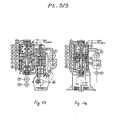
- CONDENSER (PL.3 / 8): It contains the Turbine which it serves as an ENVELOPE. Also, it is circular as well as its beam.
- the head plate of this bundle serves as the bottom on the "reducing" side, supplemented by a disc (30) carrying one of the Bearings (32) and the Oil and Steam Sealing Devices (44).
- the shaft (21) carries the turbine (20) using a disc (31) forming a thrust-axial balancing drum, provided with a HYDRAULIC SEAL OF VACUUM by centrifugal effect on the '' Water from the permanent leak in the Boiler Supply Box routed through the Conduit (31).
- the Shafts are coaxial but without any contact with each other:
- the PRIMARY Shaft (21) on the outside, rotating at 40,000 rpm, is carried by ⁇ 2 BEARINGS (32) with Double-ring lubricated by Oil according to the technique of modern Turboblowers and held in position by a Stop Disc (33) engaging in a groove:
- the SECONDARY can reach 8000 rpm is carried at its ends by 2 BALL BEARINGS, one of Stop , integrated into the Reducer.
- the bottom side "Reducer” carries a double annular water circulation box (35):
- the inlet ring serves the Outer row of tubes so that they are THE COLDEST.
- the return to the "exit" compartment is carried out by the tubes of the interior row by means of an annular collecting box (36) carried by the bundle and the central body (34).
- the supply of the annular water inlet box is done by the Pale Circulation Pump (k) directly fixed on the Device and driven like the other auxiliaries, by the PTOs (23).
- the periphery of the manifold (36) is the “cold point” (37) or sucks the "air-pump and vacuum” (x).
- the "Reducer" side is the "well” (38) where the "Water-condensed Extraction Pump” (1) flasks on the bottom (35).
- the assembly is built to support 95% of VACUUM in service.
- CONDENSER OPERATION The jets of relaxed steam coming out of the nozzles of the Turbine uniformly sweep all the tubes, being slightly deflected and helped by the centrifugal component due to the rotation at high speed: This avoids the difficulties of penetration and masking of cold surfaces by runoff encountered in condensers of conventional arrangement, at least for the lower half of the beam if the AXIS is HORIZONTAL. From this point of view (as well as for the organization of the lubrication of the speed reducer and of the functioning of the "sealed box" which separates it, in particular to avoid sucking oil), the arrangement at VERTICAL AXIS is much PREFERABLE, without being compulsory: In this case, the runoff is uniform along all the tubes.
- the "well” (38) can be located at the lowest point by positioning the hole made in the beam head plate (28) opening into a circular groove in the bottom (35) where the Extraction Pump (1) is drawn .
- Cooling is therefore MANDATORY of the "KEEL or SKIN-COOLING" type, ie indirect cooling by surfaces attached to the hull of the submarine or capacities in contact with external ner water: Also the coolant could be soft water, especially that produced by combustion if you prefer to store it rather than to push it back into the sea at the price of Imparting work of a special WATER PUMP.
- the Condenser has:
- BOILER SAFETY VALVE A safety valve (42) is mounted in the Central Body (34) at the end of the HP vapor duct supplying the engine: When relieved, the HP Steam discharged by this valve ends up in the 'entry of Steam to the Turbine (20), therefore to the Condenser: In the event of accidental overpressure, no loss of water or external release - disturbing in a submarine - is to be feared.
- this EXTERNAL COMBUSTION Engine has a trigger that transforms Calorific Energy into Mechanical Energy:
- This "regulator” is a VOLUMETRIC ENGINE or a TURBINE: Their characteristics being very different, one may be preferred to the other depending on the application.
- the Cylinders are SINGLE-EFFECT, but DOUBLE-EXPANSION (Compound), with 2-diameter pistons and "crossed" exhausts which implies, AT LEAST, AN ENGINE WITH TWO IDENTICAL CYLINDERS and a 2-STROKE Cycle:
- the cylinder H.P (1st Expansion) of small diameter is in the upper part.
- a CYLINDER HEAD is specially made to close the HP cylinder at its upper part and fixed by screws or studs installed in the HP Cylinder Body: If the overall height allows it, this cylinder head receives the steam injection valve (39) HP (head valve). Otherwise, it is housed in the HP Cylinder Body according to the classic arrangement known as "with side valve".
- the H.P Cylinder Body includes a chamber collecting the Steam of the 1st Expansion at the level of the H.P. Cylinder Lights: A Conduit made in this Cylinder Body channels it to the ADMISSION of the neighboring B.P Cylinder (Crossed exhaust)
- this Steam-Engine is of the "Equi-current" type, the steam never passing by the same way, thus avoiding alternating heating and cooling of the conduits: This arrangement considerably reduces the Heat Losses by Effect of wall.
- each HP cylinder escapes into a neighboring BP cylinder at 120 ° after.
- the height of the BP cylinder exhaust lights, controlling the DELAY POINT at the CLOSING of the BP EXHAUST, conditions the re-compression phase of this cylinder: We therefore arrange for this re-compression to be equivalent to the inlet pressure so that the effective transfer of steam from the HP to the LP only begins in the vicinity of the TOP dead center of the LP cylinder, thus neutralizing the relatively high value of the ADVANCE to the BP INTAKE OPENING (30 °).
- VAPOR INJECTION VALVE (39) placed on each HP cylinder must be, due to the high vapor pressure (100 bar), of the "balanced” type: It is however of the current "tulip" model used in DIESEL with sliding rod in a Guide.
- the lubrication of the rod in the guide is ensured, as described below, by the Hydraulic Opening control system: The leakage towards the tulip which results at each opening ensures the internal lubrication of the cylinders in which it is conveyed by the Steam-Overheated.
- the advantage of re-using the injector and its injector holder thus lies in their high availability and the economy of machining fairly expensive equivalent special parts.
- the high-pressure circuit and its directly usable connection are in fact available on the injector holder.
- INJECTION PUMP (46) It REGULATES the work of the engine by DOSING the Vapor Flow injected by Cycle and by Cylinder HP: The RAISE of the valve is almost instantaneous and has, of construction, a constant value.
- any maneuvering of the worm which modifies the angular position of the wheel carrying the satellites results in an offset of the shaft driven in relation to the shaft leading from an ANGLE EQUAL in DIRECTION -INVERSE, that is to say, give ADVANCE or DELAYED.
- the lubricating oil pump (49) must be able to pump in both directions.
- the injection of steam into the HP cylinder begins at Neutral HIGH or with a slight ADVANCE on it (approx. 10 ° from A.O.A):
- This angle is "THE MARKET TIP ANGLE”.
- This DRAWING (n) during expansion is a well-known and very effective process for improving the yield of the theoretical Rankine-Hirn cycle, which passes here from 0.42 to 0.46 for a sample of the order of 20% of the evolving mass.
- the machine can start alone (3 Cyl. At 120 °) and be used after a brief Idle Warm-up: This provided that a certain number of pressure switches and thermal switches have confirmed that everything is in order and unlocked the Lever (50 ) of the injection pump speed control which is thus authorized to leave the "Idle" position.
- step 4-7 The rotation of the planet carrier wheel enters that of the camshaft of the injection pump (46) causing an "injection” of Steam which "balance” the engine to a position favorable for departure.
- REGULATION OF HEATING AND POWER The regulation of the rotation speed and the engine load is ensured by the speed regulator, mechanical or hydraulic, of the DIESEL injection pump (46).
- Adjustment device available to the User is, as for the DIESEL, the speed control lever (50) of the Regulator which sets the Rotation speed ("All speed” regulator): But here, it acts only on the duration of steam injection and not on the quantity of fuel burned. It is therefore essential to CONTROL the "Flow injected” which controls the introduction of steam, the GAS FLOW to the burners and, if necessary, the NUMBER of BURNERS in service (The setting range of a single burner can be much too narrow).
- the Cruise Control must therefore activate, in addition to the "rack and pinion" of the injection pump, the ADJUSTING MEMBER of the GAS FLOW TO THE BURNERS in Service and A CONTACTOR controlling these Ignitions or Extensions as required.
- the expansion member of the EXTERNAL COMBUSTION engine object of the invention may be a TURBINE.
- Each expansion stage is constituted by a "PURE REACTION" type wheel with VARIABLE GEOMETRY TUYERES controlled by a centrifugal regulator, in all respects similar in principle to that already described, used as the last expansion stage and placed in the Condenser. Their number is as low as possible to limit losses and mechanical complications: Indeed these wheels are all placed on the Shaft PRIMARY that they drive at a very high speed (of the order of 40,000 rpm). However, the bearings thereof must be moved away from high temperature areas and where they can be lubricated, ie in the mechanical assembly comprising the SPEED REDUCER.
- the H.P Turbine Wheel according to PL.8 / 8 is a variant, powered by the axis, of the previously described Model (PL.2 / 8) powered by the Side and used for the MP and BP stages.
- the VERTICAL arrangement is preferable (but NOT MANDATORY) as much as it is beneficial both for the Condenser, for the drainage of the Heater (o) and for the lubrication of the Reducer (22).
- MANDATORY MANDATORY
- this arrangement is not too unfavorable if precisely, we limit the overall height by a small number of expansion stages: The ALTERNATOR placed in the lower part and which represents the greater part of the Weight of the assembly, then constitutes the Base of a Device whose Center of gravity remains sufficiently low.
- the speed of rotation of the SECONDARY shaft, after reduction is 3000 RPM to produce AC current at 50 Hertz, 3600 rpm for 60 Hertz.
- This DRAWING during relaxation is a well-known and very effective Process for improving the Yield of the Rankine-Hirn Theoretical Cycle, which passes here from 0.42 to 0.46 for a Removal of the order of 20% of the Mass evolving.
- This Regulator sensitive to the speed of the Turbo-engine and to the Steam Pressure delivered by the Boiler therefore only activates the ADJUSTING MEMBER of the GAS FLOW TO BURNERS in Service and AN ELECTROVALVE CONTACTOR controlling the Ignitions or Shutdowns according to the need.
Landscapes
- Engineering & Computer Science (AREA)
- Mechanical Engineering (AREA)
- General Engineering & Computer Science (AREA)
- Chemical & Material Sciences (AREA)
- Combustion & Propulsion (AREA)
- Engine Equipment That Uses Special Cycles (AREA)
- Fire-Extinguishing By Fire Departments, And Fire-Extinguishing Equipment And Control Thereof (AREA)
- Toys (AREA)
- Structures Of Non-Positive Displacement Pumps (AREA)
Priority Applications (1)
| Application Number | Priority Date | Filing Date | Title |
|---|---|---|---|
| AT84430032T ATE41974T1 (de) | 1983-09-15 | 1984-09-17 | Thermischer dampfmotor fuer selbstaendiges unterwasserfahrzeug, ohne verbindung mit der oberflaeche. |
Applications Claiming Priority (2)
| Application Number | Priority Date | Filing Date | Title |
|---|---|---|---|
| FR8315473 | 1983-09-15 | ||
| FR8315473A FR2552160B1 (fr) | 1983-09-15 | 1983-09-15 | Moteur thermique a vapeur pour engin submersible autonome, sans communication avec la surface |
Publications (2)
| Publication Number | Publication Date |
|---|---|
| EP0143728A1 true EP0143728A1 (de) | 1985-06-05 |
| EP0143728B1 EP0143728B1 (de) | 1989-04-05 |
Family
ID=9292644
Family Applications (1)
| Application Number | Title | Priority Date | Filing Date |
|---|---|---|---|
| EP84430032A Expired EP0143728B1 (de) | 1983-09-15 | 1984-09-17 | Thermischer Dampfmotor für selbständiges Unterwasserfahrzeug, ohne Verbindung mit der Oberfläche |
Country Status (4)
| Country | Link |
|---|---|
| EP (1) | EP0143728B1 (de) |
| AT (1) | ATE41974T1 (de) |
| DE (1) | DE3477597D1 (de) |
| FR (1) | FR2552160B1 (de) |
Cited By (3)
| Publication number | Priority date | Publication date | Assignee | Title |
|---|---|---|---|---|
| WO1990008693A1 (en) * | 1989-02-02 | 1990-08-09 | C.D.S.S. Limited | Recirculatory system |
| FR2661453A1 (fr) * | 1990-04-26 | 1991-10-31 | Bertin & Cie | Generateur autonome d'energie thermique et module energetique sous-marin comprenant un tel generateur. |
| US10030961B2 (en) | 2015-11-27 | 2018-07-24 | General Electric Company | Gap measuring device |
Families Citing this family (2)
| Publication number | Priority date | Publication date | Assignee | Title |
|---|---|---|---|---|
| FR2644206B1 (fr) * | 1989-03-13 | 1991-06-21 | Bech Jean | Machine thermique a vapeur a combustion externe et procede pour son fonctionnement a l'air atmospherique ou en chambre close |
| ES2488123T3 (es) | 2010-06-15 | 2014-08-26 | Astrium Gmbh | Procedimiento para la regeneración de un medio de adsorción o medio de absorción |
Citations (6)
| Publication number | Priority date | Publication date | Assignee | Title |
|---|---|---|---|---|
| US2525804A (en) * | 1945-05-02 | 1950-10-17 | Robert B Kellogg | Aircraft rotary boiler turbine air condenser power plant |
| US3559402A (en) * | 1969-04-24 | 1971-02-02 | Us Navy | Closed cycle diesel engine |
| FR2118343A5 (de) * | 1970-12-18 | 1972-07-28 | Liautaud Jean | |
| US3769796A (en) * | 1971-12-10 | 1973-11-06 | Du Pont | Rotary heat engines |
| US3775976A (en) | 1972-05-26 | 1973-12-04 | Us Navy | Lox heat sink system for underwater thermal propulsion system |
| US3950950A (en) | 1975-05-05 | 1976-04-20 | E. I. Du Pont De Nemours And Company | Rotary Rankine engine powered electric generating apparatus |
-
1983
- 1983-09-15 FR FR8315473A patent/FR2552160B1/fr not_active Expired
-
1984
- 1984-09-17 DE DE8484430032T patent/DE3477597D1/de not_active Expired
- 1984-09-17 EP EP84430032A patent/EP0143728B1/de not_active Expired
- 1984-09-17 AT AT84430032T patent/ATE41974T1/de active
Patent Citations (6)
| Publication number | Priority date | Publication date | Assignee | Title |
|---|---|---|---|---|
| US2525804A (en) * | 1945-05-02 | 1950-10-17 | Robert B Kellogg | Aircraft rotary boiler turbine air condenser power plant |
| US3559402A (en) * | 1969-04-24 | 1971-02-02 | Us Navy | Closed cycle diesel engine |
| FR2118343A5 (de) * | 1970-12-18 | 1972-07-28 | Liautaud Jean | |
| US3769796A (en) * | 1971-12-10 | 1973-11-06 | Du Pont | Rotary heat engines |
| US3775976A (en) | 1972-05-26 | 1973-12-04 | Us Navy | Lox heat sink system for underwater thermal propulsion system |
| US3950950A (en) | 1975-05-05 | 1976-04-20 | E. I. Du Pont De Nemours And Company | Rotary Rankine engine powered electric generating apparatus |
Cited By (6)
| Publication number | Priority date | Publication date | Assignee | Title |
|---|---|---|---|---|
| WO1990008693A1 (en) * | 1989-02-02 | 1990-08-09 | C.D.S.S. Limited | Recirculatory system |
| GB2246085A (en) * | 1989-02-02 | 1992-01-22 | Cdss Ltd | Recirculatory system |
| GB2246085B (en) * | 1989-02-02 | 1992-12-02 | Cdss Ltd | Recirculatory system |
| FR2661453A1 (fr) * | 1990-04-26 | 1991-10-31 | Bertin & Cie | Generateur autonome d'energie thermique et module energetique sous-marin comprenant un tel generateur. |
| WO1991016526A1 (fr) * | 1990-04-26 | 1991-10-31 | Bertin & Cie | Generateur autonome d'energie thermique et module energetique sous-marin comprenant un tel generateur |
| US10030961B2 (en) | 2015-11-27 | 2018-07-24 | General Electric Company | Gap measuring device |
Also Published As
| Publication number | Publication date |
|---|---|
| FR2552160B1 (fr) | 1987-12-04 |
| ATE41974T1 (de) | 1989-04-15 |
| FR2552160A1 (fr) | 1985-03-22 |
| DE3477597D1 (en) | 1989-05-11 |
| EP0143728B1 (de) | 1989-04-05 |
Similar Documents
| Publication | Publication Date | Title |
|---|---|---|
| EP3218639B1 (de) | Vorrichtung und verfahren zum kühlen eines flüssiggases | |
| AU2005284864B2 (en) | Heat regenerative engine | |
| FR2624200A1 (fr) | Systeme pour le traitement et le stockage cryogeniques des produits de combustion d'un moteur thermique | |
| FR3040773A1 (fr) | Systeme et procede de traitement de gaz issu de l'evaporation d'un liquide cryogenique | |
| EP0143728B1 (de) | Thermischer Dampfmotor für selbständiges Unterwasserfahrzeug, ohne Verbindung mit der Oberfläche | |
| EP2816013B1 (de) | Hybridmotorsystem, das eine Kombination aus zwei komplementären Motorkreisläufen umfasst | |
| CN101265838A (zh) | 固体燃料内燃机 | |
| EP1488843A1 (de) | Verfahren zur Behandlung von Rauchgasen | |
| EP1486246A2 (de) | Verfahren zur Behandlung von Rauchgasen mit Energierückgewinnung | |
| WO2022064152A1 (fr) | Moteur a vapeur perfectionne | |
| EP0388337B1 (de) | Dampfmaschine mit äusserer Verbrennung und Betriebsverfahren dafür mit atmospherischer Luft oder in geschlossenem Raum | |
| FR2491135A1 (fr) | Mecanisme de turbines a gaz | |
| EP3189224B1 (de) | Motor mit differentiellen verdampfungsdrücken | |
| EP1426586A1 (de) | Turbomotor mit Holzgasgenerator | |
| FR2607581A1 (fr) | Convertisseur de chaleur ambiante | |
| FR3059355B1 (fr) | Installation de production d'energie electrique, d'energie mecanique et/ou de froid | |
| BE487485A (de) | ||
| RU2184259C2 (ru) | Двигатель внутреннего теплообмена с преобразованием тепловой энергии газов в механическое давление газов | |
| CA2080689A1 (fr) | Generateur autonome d'energie electrique et module energetique sous-marin comprenant un tel generateur | |
| BE514603A (de) | ||
| FR2607551A1 (fr) | Moteurs a distribution rotative et modules a explosion exterieurs | |
| BE356052A (de) | ||
| BE465149A (de) | ||
| BE342996A (de) | ||
| BE427721A (de) |
Legal Events
| Date | Code | Title | Description |
|---|---|---|---|
| PUAI | Public reference made under article 153(3) epc to a published international application that has entered the european phase |
Free format text: ORIGINAL CODE: 0009012 |
|
| 17P | Request for examination filed |
Effective date: 19840921 |
|
| AK | Designated contracting states |
Designated state(s): AT BE CH DE FR GB IT LI LU NL SE |
|
| 17Q | First examination report despatched |
Effective date: 19860604 |
|
| GRAA | (expected) grant |
Free format text: ORIGINAL CODE: 0009210 |
|
| AK | Designated contracting states |
Kind code of ref document: B1 Designated state(s): AT BE CH DE FR GB IT LI LU NL SE |
|
| PG25 | Lapsed in a contracting state [announced via postgrant information from national office to epo] |
Ref country code: NL Effective date: 19890405 Ref country code: AT Effective date: 19890405 |
|
| REF | Corresponds to: |
Ref document number: 41974 Country of ref document: AT Date of ref document: 19890415 Kind code of ref document: T |
|
| REF | Corresponds to: |
Ref document number: 3477597 Country of ref document: DE Date of ref document: 19890511 |
|
| ITF | It: translation for a ep patent filed | ||
| GBT | Gb: translation of ep patent filed (gb section 77(6)(a)/1977) | ||
| NLV1 | Nl: lapsed or annulled due to failure to fulfill the requirements of art. 29p and 29m of the patents act | ||
| PLBE | No opposition filed within time limit |
Free format text: ORIGINAL CODE: 0009261 |
|
| STAA | Information on the status of an ep patent application or granted ep patent |
Free format text: STATUS: NO OPPOSITION FILED WITHIN TIME LIMIT |
|
| 26N | No opposition filed | ||
| PGFP | Annual fee paid to national office [announced via postgrant information from national office to epo] |
Ref country code: LU Payment date: 19920921 Year of fee payment: 9 |
|
| EPTA | Lu: last paid annual fee | ||
| PG25 | Lapsed in a contracting state [announced via postgrant information from national office to epo] |
Ref country code: LU Free format text: LAPSE BECAUSE OF NON-PAYMENT OF DUE FEES Effective date: 19930917 |
|
| PGFP | Annual fee paid to national office [announced via postgrant information from national office to epo] |
Ref country code: GB Payment date: 19930929 Year of fee payment: 10 |
|
| ITTA | It: last paid annual fee | ||
| PGFP | Annual fee paid to national office [announced via postgrant information from national office to epo] |
Ref country code: SE Payment date: 19930930 Year of fee payment: 10 Ref country code: FR Payment date: 19930930 Year of fee payment: 10 |
|
| PGFP | Annual fee paid to national office [announced via postgrant information from national office to epo] |
Ref country code: BE Payment date: 19931018 Year of fee payment: 10 |
|
| PGFP | Annual fee paid to national office [announced via postgrant information from national office to epo] |
Ref country code: CH Payment date: 19931029 Year of fee payment: 10 |
|
| PGFP | Annual fee paid to national office [announced via postgrant information from national office to epo] |
Ref country code: DE Payment date: 19931126 Year of fee payment: 10 |
|
| PG25 | Lapsed in a contracting state [announced via postgrant information from national office to epo] |
Ref country code: GB Effective date: 19940917 |
|
| PG25 | Lapsed in a contracting state [announced via postgrant information from national office to epo] |
Ref country code: SE Effective date: 19940918 |
|
| PG25 | Lapsed in a contracting state [announced via postgrant information from national office to epo] |
Ref country code: LI Effective date: 19940930 Ref country code: CH Effective date: 19940930 Ref country code: BE Effective date: 19940930 |
|
| EAL | Se: european patent in force in sweden |
Ref document number: 84430032.7 |
|
| BERE | Be: lapsed |
Owner name: BECH JEAN Effective date: 19940930 |
|
| GBPC | Gb: european patent ceased through non-payment of renewal fee |
Effective date: 19940917 |
|
| PG25 | Lapsed in a contracting state [announced via postgrant information from national office to epo] |
Ref country code: FR Effective date: 19950531 |
|
| REG | Reference to a national code |
Ref country code: CH Ref legal event code: PL |
|
| PG25 | Lapsed in a contracting state [announced via postgrant information from national office to epo] |
Ref country code: DE Effective date: 19950601 |
|
| EUG | Se: european patent has lapsed |
Ref document number: 84430032.7 |
|
| REG | Reference to a national code |
Ref country code: FR Ref legal event code: ST |