EP0143852B1 - Systeme de detection de position absolue dans un systeme de servo-commande - Google Patents
Systeme de detection de position absolue dans un systeme de servo-commande Download PDFInfo
- Publication number
- EP0143852B1 EP0143852B1 EP84901427A EP84901427A EP0143852B1 EP 0143852 B1 EP0143852 B1 EP 0143852B1 EP 84901427 A EP84901427 A EP 84901427A EP 84901427 A EP84901427 A EP 84901427A EP 0143852 B1 EP0143852 B1 EP 0143852B1
- Authority
- EP
- European Patent Office
- Prior art keywords
- absolute
- resolver
- grid
- absolute position
- absolute encoder
- Prior art date
- Legal status (The legal status is an assumption and is not a legal conclusion. Google has not performed a legal analysis and makes no representation as to the accuracy of the status listed.)
- Expired - Lifetime
Links
Images


Classifications
-
- G—PHYSICS
- G05—CONTROLLING; REGULATING
- G05B—CONTROL OR REGULATING SYSTEMS IN GENERAL; FUNCTIONAL ELEMENTS OF SUCH SYSTEMS; MONITORING OR TESTING ARRANGEMENTS FOR SUCH SYSTEMS OR ELEMENTS
- G05B19/00—Program-control systems
- G05B19/02—Program-control systems electric
- G05B19/18—Numerical control [NC], i.e. automatically operating machines, in particular machine tools, e.g. in a manufacturing environment, so as to execute positioning, movement or co-ordinated operations by means of program data in numerical form
- G05B19/406—Numerical control [NC], i.e. automatically operating machines, in particular machine tools, e.g. in a manufacturing environment, so as to execute positioning, movement or co-ordinated operations by means of program data in numerical form characterised by monitoring or safety
- G05B19/4062—Monitoring servoloop, e.g. overload of servomotor, loss of feedback or reference
-
- G—PHYSICS
- G01—MEASURING; TESTING
- G01B—MEASURING LENGTH, THICKNESS OR SIMILAR LINEAR DIMENSIONS; MEASURING ANGLES; MEASURING AREAS; MEASURING IRREGULARITIES OF SURFACES OR CONTOURS
- G01B7/00—Measuring arrangements characterised by the use of electric or magnetic techniques
- G01B7/003—Measuring arrangements characterised by the use of electric or magnetic techniques for measuring position, not involving coordinate determination
-
- G—PHYSICS
- G01—MEASURING; TESTING
- G01D—MEASURING NOT SPECIALLY ADAPTED FOR A SPECIFIC VARIABLE; ARRANGEMENTS FOR MEASURING TWO OR MORE VARIABLES NOT COVERED IN A SINGLE OTHER SUBCLASS; TARIFF METERING APPARATUS; MEASURING OR TESTING NOT OTHERWISE PROVIDED FOR
- G01D3/00—Indicating or recording apparatus with provision for the special purposes referred to in the subgroups
- G01D3/08—Indicating or recording apparatus with provision for the special purposes referred to in the subgroups with provision for safeguarding the apparatus, e.g. against abnormal operation, against breakdown
-
- G—PHYSICS
- G01—MEASURING; TESTING
- G01D—MEASURING NOT SPECIALLY ADAPTED FOR A SPECIFIC VARIABLE; ARRANGEMENTS FOR MEASURING TWO OR MORE VARIABLES NOT COVERED IN A SINGLE OTHER SUBCLASS; TARIFF METERING APPARATUS; MEASURING OR TESTING NOT OTHERWISE PROVIDED FOR
- G01D5/00—Mechanical means for transferring the output of a sensing member; Means for converting the output of a sensing member to another variable where the form or nature of the sensing member does not constrain the means for converting; Transducers not specially adapted for a specific variable
- G01D5/12—Mechanical means for transferring the output of a sensing member; Means for converting the output of a sensing member to another variable where the form or nature of the sensing member does not constrain the means for converting; Transducers not specially adapted for a specific variable using electric or magnetic means
- G01D5/244—Mechanical means for transferring the output of a sensing member; Means for converting the output of a sensing member to another variable where the form or nature of the sensing member does not constrain the means for converting; Transducers not specially adapted for a specific variable using electric or magnetic means influencing characteristics of pulses or pulse trains; generating pulses or pulse trains
- G01D5/245—Mechanical means for transferring the output of a sensing member; Means for converting the output of a sensing member to another variable where the form or nature of the sensing member does not constrain the means for converting; Transducers not specially adapted for a specific variable using electric or magnetic means influencing characteristics of pulses or pulse trains; generating pulses or pulse trains using a variable number of pulses in a train
- G01D5/2454—Encoders incorporating incremental and absolute signals
- G01D5/2458—Encoders incorporating incremental and absolute signals with incremental and absolute tracks on separate encoders
-
- G—PHYSICS
- G05—CONTROLLING; REGULATING
- G05B—CONTROL OR REGULATING SYSTEMS IN GENERAL; FUNCTIONAL ELEMENTS OF SUCH SYSTEMS; MONITORING OR TESTING ARRANGEMENTS FOR SUCH SYSTEMS OR ELEMENTS
- G05B19/00—Program-control systems
- G05B19/02—Program-control systems electric
- G05B19/18—Numerical control [NC], i.e. automatically operating machines, in particular machine tools, e.g. in a manufacturing environment, so as to execute positioning, movement or co-ordinated operations by means of program data in numerical form
- G05B19/19—Numerical control [NC], i.e. automatically operating machines, in particular machine tools, e.g. in a manufacturing environment, so as to execute positioning, movement or co-ordinated operations by means of program data in numerical form characterised by positioning or contouring control systems, e.g. to control position from one programmed point to another or to control movement along a programmed continuous path
- G05B19/39—Numerical control [NC], i.e. automatically operating machines, in particular machine tools, e.g. in a manufacturing environment, so as to execute positioning, movement or co-ordinated operations by means of program data in numerical form characterised by positioning or contouring control systems, e.g. to control position from one programmed point to another or to control movement along a programmed continuous path using a combination of the means covered by at least two of the preceding groups G05B19/21, G05B19/27 and G05B19/33
Definitions
- the present invention relates to a system for detecting the absolute position of an operating shaft under servocontrol of a servomotor.
- Servomotors are widely used for positioning a movable portion of an industrial robot, machine tool or the like with a high accuracy, the servomotors being subjected to servo-control.
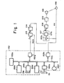
- Fig. 1 is a block diagram explanatory of such servocontrol, showing an example in which an operating shaft of an industrial robot or the like is positionally controlled by an NC (numerical control) apparatus.
- Designated in Fig. 1 at 101 is a paper tape punched with NC command data such as positioning information for machining, M, S, T function information, etc., and 102 an NC apparatus for enabling a tape reader, described later, to read NC data from the paper tape 101, encoding the read NC data, feeding M, S, T function commands, etc. to the machine through a driver, not shown, and feeding a movement command Zc to a following pulse distributor.
- NC command data such as positioning information for machining, M, S, T function information, etc.
- 102 an NC apparatus for enabling a tape reader, described later, to read NC data from the paper tape 101, encoding the read NC data, feeding M, S, T function commands, etc. to the machine through a driver, not shown, and feeding a movement command Zc to a
- the NC apparatus 102 is composed of a processor 102a for effecting arithmetic operations according to a control program, a program memory 102 storing the control program, a data memory 102c for storing data, an operator's console 102d for effecting control a tape reader/puncher 102e, a display unit 102f, an input/output port 102g, a current position counter 102h, and an address/data bus 102 interconnecting the above components.
- Denoted at 103 is the pulse distributor for effecting a known pulse distributing arithmetic operation based on the movement command Zc to generate distributed pulses Ps having a frequency dependent on a command speed.
- 104 is a known acceleration and deceleration circuit for producing a pulse train Pi by rectilinearly increasing the pulse rate of the distributed pulse train Ps at the time it is generated, and by rectilinearly reducing the pulse rate at the time it is ended.
- the 105 is a servomotor for driving an operating shaft, 106 a pulse coder for generating one feedback pulse FP each time the motor 105 rotates through a prescribed interval, and 107 an error calculating and storing unit provided as a reversible counter for storing the difference Er between the number of input pulses Pi generated by the acceleration and deceleration circuit 104 and the number of feedback pulses FP.
- the error calculating and storing unit comprises, as shown, an arithmetic circuit 107a for calculating the difference Er between Pi and FP, and an error register 107b for storing Er.
- the error calculating and storing unit 107 counts up the pulse Pi each time it is generated, counts down the feedback pulse FP each time it is generated, and stores the difference Er between the number of the input pulses and the number of the feedback pulses in the error register 107b.
- 108 denotes a digital-to-analog (DA) converter for generating an analog voltage in proportion to the content of the error register 107b, and 109 a speed control circuit.
- the error calculating and storing unit 107 and the DA converter 108 constitute a motor position control circuit.
- the NC data on the paper tape 101 is read by the tape reader/puncher 102e and stored through the bus 102j into the data memory 102c. Then a start command is applied via the bus 102j to the processor 102a in response to operation of the operator's console 102d. Then, the operator's console 102d is operated-upon to successively read the machining control program out of the program memory 102d and execute the machining control program.
- the NC data is read from the data memory 102c and at the same time necessary parameters (NC parameter, feed speed, machining voltage, etc.) are read to produce an X-axis movement command Xc and a Y-xis movement command Yc for moving a table, not shown, in X and Y directions, the commands being fed through the input/output port, not shown, to a table driver for positioning the table.
- necessary parameters NC parameter, feed speed, machining voltage, etc.
- the shown Z-axis movement command Zc is produced, and M, X, T function commands are delivered through the input/output port 102g to the machine.
- the movement command Zc is issued through the bus 102j to the input/output port 102g.
- the pulse distributor 103 effects a pulse distributing arithmetic operation based on the movement command Zc to issue distributed pulses Ps, which are applied to the acceleration and deceleration cirucit 104 to increase or reduce the pulse rate for supplying a command pulse train Pi to the error calculating and storing unit 107.
- a voltage is supplied from the DA converter 108 to enable the speed control circuit 109 to drive the motor 105 for driving the operating shaft.
- feedback pulses FP are generated by the pulse coder 106 and applied to the error calculating and storing unit 107, and the error register 107b now stores the difference Er between the number of command pulses Pi and the number of feedback pulses FP.
- the motor 105 is then subjected to servocontrol so as to bring the error Er to zero for driving the operating shaft to a target position.
- the current position is determined by the counter 102h by employing the feedback pulse FP from the pulse coder 106, which are also utilized for positional control.
- the pulse coder 106 has a high resolving accuracy and is capable of highly accurate positional control. Therefore, this pulse coder is better than other detectors such as a resolver as a detector for positional control.
- the pulse coder since the pulse coder has no absolute position detecting function, it will be necessary to effect an origin-return operation when the absolute position of the operating shaft is lost (as when the servo system malfunctions or a power supply is switched on).
- the origin-return operation requires a complex mode of control and is time-consuming. Therefore, there is desired a new system for detecting an absolute position without effecting the origin-return operation.
- US-A-4 085 890 discloses an absolute position detecting system for a servocontrol system in which the detection of the absolute position is based on the outputs of two pulse generators arranged to rotate relatively to one another at a fixed ratio. One of these pulse generators measures the position absolutely and its signal is converted into the measuring unit of the other pulse generator.
- an absolute encoder and a resolver as positional detectors capable of detecting an absolute position.
- the absolute encoder serves to issue an absolute position corresponding to a rotational angle of the operating shaft.
- the reservoir has, as shown in Fig. 2, a rotor 202a, a rotor winding 202b, two stator windings 202c, 202d positioned 90° out of phase with each other, and carrier generator circuit 202e, 202f for generating carriers of sin wt, sin wt, respectively. If the rotor 202a is in the position of an angle 8, then the rotor winding 202b develops a voltage e expressed as follows:
- the relationship between the carrier sin wt and the output e from the resolver 202 is illustrated in Fig. 3.
- the absolute position can be determined by finding the phase differences 01-E), with the carrier sin wt.
- the full stroke of the movable portion to be detected positionally is generally achieved by n (100, for example) revolutions of the motor. Therefore, the resolution is 1/n with respect to one revolution of the motor, resulting in a failure to achieve a sufficient positional accuracy. No increased positional control accuracy can be accomplished unless the accuracy of detecting the absolute position is compatible with a high resolution of the pulse coder.
- an absolute position detecting system for a servocontrol system for servo-controlling a servomotor arranged for driving an operating shaft of a machine comprising for said shaft a rough position detector in the form of a resolver and an accurate position detector in the form of an absolute encoder arranged to rotate at a predetermined revolutions ratio of 1:m with respect to one another, wherein the system is such that in use the resolver outputs a coarse grid of detected position signals and the absolute encoder outputs a fine grid of detected position signals, a detected grid position within said coarse grid and outputted by the resolver is converted into the corresponding grid position within the fine grid of the absolute encoder, and the absolute position of the shaft is detected accurately in dependence upon the converted grid position and upon the output of the absolute encoder.
- Fig. 1 is a block diagram of a general servocontrol system
- Fig. 2 is a view showing the arrangement of a resolver employed in an embodiment of the present invention
- Fig. 3 is a diagram illustrative of operation of the arrangement of Fig. 2
- Fig. 4 is a block diagram of an embodiment of the present invention
- Fig. 5 is a diagram explanatory of operation of the embodiment of Fig. 4.
- Fig. 4 is a diagram showing the arrangement of an embodiment of the present invention
- Fig. 5 is a diagram explanatory of the embodiment. Parts identical to those in Figs. 1 and 2 are denoted by identical reference characters.
- Denoted at 110 is an absolute encoder which, together with the pulse coder 106, is directly coupled to a rotational shaft of the motor 105.
- the absolute encoder 110 is composed of a disk bearing on a circumference thereof marks (codes) corresponding to rotational positions, and an optical readout means for reading the codes at certain positions.
- the absolute encoder may be integral with the pulse coder 106.
- Designated at 111a, 111 b are gears mounted respectively on the rotational shafts of the motor 105 and a resolver 202, for transmitting rotation of the motor 105 to the resolver 202.
- the full stroke of a movable portion drivable by rotation of the motor 105 along an operating shaft is indicated by I while the number of revolutions of the motor 105 is indicated by m (which need not be limited to an integer).
- the gear ratio of the gears 111a, 111b is determined so that the resolver 202 makes one revolution when the motor makes m revolutions. Therefore, the resolver 202 makes one revolution upon movement across the full stroke.
- PCC Denoted at PCC is a positional control circuit including the error calculating und storing unit 107, the DA converter 108, and the current position counter 102h as shown in Fig. 1.
- Designated at RPC is a resolver detecting circuit for detecting a phase difference from an output of the resolver 202 and issuing a grid position ri.
- Denoted at APC is an absolute position detecting circuit for detecting an absolute position A from the grid position ri and an output ah of the absolute encoder 110.
- the grid position ri is obtained from the resolver detecting circuit RPC based on the output from the resolver 202. More specifically, the detecting circuit RPC determines a mechanical angle of the resolver 202 from an electrical angle of the output from the resolver 202 to calculate the grid position ri. Since the resolver 202 makes one revolution in response to m revolutions (corresponding to the movement across the full stroke I) of the motor 105, the mechanical angle corresponds to the position of a point A.
- the resolver 202 has a resolution n and the number of r.p.m. of i, Although it is said that the resolution n of the resolver 202 is 4000, it has a large error and the actual resolution n is about 1000.
- the grid position ri is converted into a grid position of the absolute encoder 110.
- the absolute encoder 110 divides the interval of each 1/4 revolution of the motor 105 into 16 sections and issues absolute positions a,-al6 corresponding respectively to the divided sections. Therefore, the absolute positions a,-a,., are issued four times per revolution of the motor 105.
- the grid position ri is converted into a grid position Pjk of the absolute encoder 110 at the time the motor 105 makes the ith revolution. This can easily be determined since the resolution n and the number m of r.p.m of the motor 105 are already known.
- the detecting circuit APC thus determines the grid position Pjk in the above manner, and the absolute position of the point A can be determined by reading the detected output ah of the absolute encoder 110 and combining the same with the above grid position.
- the resolution becomes 64m as compared with ths resolution n of the resolver 202.
- the actual resolution of the resolver is about n/4, a resolution which is 6.4 times the actual resolution of the resolver is obtained. With the resolution converted into a full stroke, positions can be detected at about 1.5 mm steps.
- the absolute position x thus detected is set in the current position counter 102h.
- the absolution position is detected, and thereafter pulses are applied to rotate the motor 105 at a low speed in a fixed direction, and the application of the pulses to the motor 105 is stopped when the detected output of the absolute encoder 110 is increased from ah to ah+1. Then, ah+1, instead of ah, is regarded as the absolute position.
- the absolute position of the operating shaft with respect to the full stroke can be detected with a high accuracy based on the detected output of the resolver and the detected output of the absolute encoder, and no positional accuracy of the servo system is impaired.
- the resolver and the absolute encoder which rotate with the servomotor are rotated at a certain ratio, and the absolute position of the operating shaft can be detected with a high accuracy from the value of the resolver output converted into the unit grid value of the absolute encoder and the output of the absolute encoder.
- the present invention is highly effective when employed for operation control of a machine tool or the like under NC.
Landscapes
- Physics & Mathematics (AREA)
- General Physics & Mathematics (AREA)
- Engineering & Computer Science (AREA)
- Human Computer Interaction (AREA)
- Manufacturing & Machinery (AREA)
- Automation & Control Theory (AREA)
- Control Of Position Or Direction (AREA)
- Transmission And Conversion Of Sensor Element Output (AREA)
- Numerical Control (AREA)
- Measurement Of Length, Angles, Or The Like Using Electric Or Magnetic Means (AREA)
Abstract
Claims (3)
Applications Claiming Priority (2)
| Application Number | Priority Date | Filing Date | Title |
|---|---|---|---|
| JP63332/83 | 1983-04-11 | ||
| JP58063333A JPS59188518A (ja) | 1983-04-11 | 1983-04-11 | サ−ボ制御系の絶対位置検出方式 |
Publications (3)
| Publication Number | Publication Date |
|---|---|
| EP0143852A1 EP0143852A1 (fr) | 1985-06-12 |
| EP0143852A4 EP0143852A4 (fr) | 1987-01-28 |
| EP0143852B1 true EP0143852B1 (fr) | 1990-09-19 |
Family
ID=13226209
Family Applications (1)
| Application Number | Title | Priority Date | Filing Date |
|---|---|---|---|
| EP84901427A Expired - Lifetime EP0143852B1 (fr) | 1983-04-11 | 1984-04-11 | Systeme de detection de position absolue dans un systeme de servo-commande |
Country Status (5)
| Country | Link |
|---|---|
| US (1) | US4575666A (fr) |
| EP (1) | EP0143852B1 (fr) |
| JP (1) | JPS59188518A (fr) |
| DE (1) | DE3483235D1 (fr) |
| WO (1) | WO1984004162A1 (fr) |
Families Citing this family (26)
| Publication number | Priority date | Publication date | Assignee | Title |
|---|---|---|---|---|
| JPS6294251A (ja) * | 1985-10-17 | 1987-04-30 | Toshiba Mach Co Ltd | 位置制御装置 |
| US4703238A (en) * | 1987-01-13 | 1987-10-27 | Design Components, Incorporated | Amplifier system for D.C. motor |
| JP2525849B2 (ja) * | 1988-02-24 | 1996-08-21 | ファナック株式会社 | 原点復帰方法 |
| JP2702499B2 (ja) * | 1988-04-20 | 1998-01-21 | ファナック株式会社 | サーボモータ制御方法 |
| JPH0210796U (fr) * | 1988-06-28 | 1990-01-23 | ||
| US5191271A (en) * | 1988-11-04 | 1993-03-02 | Kuka Schweissanlagen & Roboter Gmbh | Process and device for adjusting an axis |
| SE8902416L (sv) * | 1989-07-04 | 1991-01-05 | Asea Brown Boveri | Absolutmaetande laegesgivarutrustning foer industrirobot |
| JP2935713B2 (ja) * | 1989-08-22 | 1999-08-16 | ファナック株式会社 | 数値制御装置 |
| US5093610A (en) * | 1990-02-12 | 1992-03-03 | Abb Robotics Inc. | Apparatus for absolute position measurement |
| US5075870A (en) * | 1990-06-27 | 1991-12-24 | Kabushiki Kaisha Kobe Seiko Sho | Method and device for determining whether or not origin return operation for industrial robot is required |
| JPH04294406A (ja) * | 1991-03-22 | 1992-10-19 | Kobe Steel Ltd | ロボットの回転位置検出装置 |
| US5640835A (en) * | 1991-10-16 | 1997-06-24 | Muscoplat; Richard | Multiple envelope with integrally formed and printed contents and return envelope |
| FR2703450A1 (fr) * | 1993-03-31 | 1994-10-07 | Aut Comp | Codeur numérique incrémental absolu, installation et machine comportant ce codeur. |
| JP3170449B2 (ja) * | 1996-03-25 | 2001-05-28 | オークマ株式会社 | アブソリュートエンコーダ |
| US6323614B1 (en) * | 1998-09-04 | 2001-11-27 | The Texas A&M University System | System and method for controlling suspension using a magnetic field |
| DE19840665C2 (de) * | 1998-09-05 | 2002-08-14 | Oechsler Ag | Verfahren zum Aufbringen einer Sensor-Stromschleife auf einen Leitungsträger sowie induktiver Sensor |
| US6750626B2 (en) * | 2002-09-11 | 2004-06-15 | Ford Global Technologies, Llc | Diagnostic strategy for an electric motor using sensorless control and a position sensor |
| JP2005221258A (ja) * | 2004-02-03 | 2005-08-18 | Fanuc Ltd | エンコーダ |
| US7273067B2 (en) * | 2005-04-14 | 2007-09-25 | Honeywell International, Inc. | Reduced profile electromechanical valve actuator |
| DE102008031620A1 (de) * | 2008-07-07 | 2010-01-14 | Continental Automotive Gmbh | Verfahren und Vorrichtung zur Ansteuerung von bürstenlosen (EC)-Elektromotoren |
| US7960934B2 (en) * | 2008-09-23 | 2011-06-14 | Honeywell International Inc. | Fault-tolerant control system |
| CN101660226B (zh) * | 2009-04-24 | 2010-12-29 | 上海一纺机械有限公司 | 一种增强精梳机分离罗拉伺服电机传动功率的结构 |
| JP5810552B2 (ja) * | 2011-02-25 | 2015-11-11 | 日本精工株式会社 | モータ回転角度検出装置及び搬送装置 |
| JP5980965B2 (ja) * | 2015-01-08 | 2016-08-31 | ファナック株式会社 | 複数の回転角検出器により回転角を更新するロボット制御装置 |
| JP7056367B2 (ja) * | 2018-05-17 | 2022-04-19 | トヨタ自動車株式会社 | 認識エラー検出装置、電動ブレーキ制御装置 |
| JP7160737B2 (ja) * | 2019-03-25 | 2022-10-25 | ファナック株式会社 | 機械の制御装置 |
Citations (1)
| Publication number | Priority date | Publication date | Assignee | Title |
|---|---|---|---|---|
| US4085890A (en) * | 1976-02-20 | 1978-04-25 | Okuma Machinery Works Ltd. | Position detecting system |
Family Cites Families (13)
| Publication number | Priority date | Publication date | Assignee | Title |
|---|---|---|---|---|
| US3551656A (en) * | 1965-04-12 | 1970-12-29 | Giddings & Lewis | Numerical control system |
| JPS526180B2 (fr) * | 1972-11-14 | 1977-02-19 | ||
| US3904944A (en) * | 1974-01-02 | 1975-09-09 | Babcock & Wilcox Co | Machine tool control |
| US4023085A (en) * | 1975-08-06 | 1977-05-10 | General Electric Company | Numerical control system having a digitized phase loop |
| CA1080326A (fr) * | 1975-12-18 | 1980-06-24 | Marvin Masel | Transducteurs de position d'arbre a grande resolution et a gamme etendue |
| JPS52132858A (en) * | 1976-04-30 | 1977-11-07 | Sakura Sokki Kk | Analogue to digital converter |
| JPS5316695A (en) * | 1976-07-29 | 1978-02-15 | Omron Tateisi Electronics Co | Processing apparatus for transaction |
| JPS5418767A (en) * | 1977-07-12 | 1979-02-13 | Toshiba Corp | Digital position detector |
| JPS5420760A (en) * | 1977-07-15 | 1979-02-16 | Toshiba Corp | Digital position detector |
| JPS56135102A (en) * | 1980-03-25 | 1981-10-22 | Mitsubishi Electric Corp | Angle detector |
| JPS58204311A (ja) * | 1982-05-24 | 1983-11-29 | Mitsubishi Electric Corp | 絶対位置検出装置 |
| JPS5946506A (ja) * | 1982-09-10 | 1984-03-15 | Hitachi Ltd | 2速シンクロ式位置検出装置 |
| JPS5990114A (ja) * | 1982-11-15 | 1984-05-24 | Toshiba Mach Co Ltd | レゾルバによる位置決め装置 |
-
1983
- 1983-04-11 JP JP58063333A patent/JPS59188518A/ja active Pending
-
1984
- 1984-04-11 EP EP84901427A patent/EP0143852B1/fr not_active Expired - Lifetime
- 1984-04-11 WO PCT/JP1984/000185 patent/WO1984004162A1/fr not_active Ceased
- 1984-04-11 US US06/688,049 patent/US4575666A/en not_active Expired - Fee Related
- 1984-04-11 DE DE8484901426T patent/DE3483235D1/de not_active Expired - Lifetime
Patent Citations (1)
| Publication number | Priority date | Publication date | Assignee | Title |
|---|---|---|---|---|
| US4085890A (en) * | 1976-02-20 | 1978-04-25 | Okuma Machinery Works Ltd. | Position detecting system |
Also Published As
| Publication number | Publication date |
|---|---|
| WO1984004162A1 (fr) | 1984-10-25 |
| EP0143852A4 (fr) | 1987-01-28 |
| US4575666A (en) | 1986-03-11 |
| DE3483235D1 (de) | 1990-10-25 |
| JPS59188518A (ja) | 1984-10-25 |
| EP0143852A1 (fr) | 1985-06-12 |
Similar Documents
| Publication | Publication Date | Title |
|---|---|---|
| EP0143852B1 (fr) | Systeme de detection de position absolue dans un systeme de servo-commande | |
| EP0139769B1 (fr) | Systeme de detection de la position absolue d'un systeme de servo-commande | |
| US2784359A (en) | Digital curve generator | |
| US4639653A (en) | Method and apparatus for performing work in a three dimensional space | |
| EP0077178B1 (fr) | Système de régulation de moteur pour fonctionnement en synchronisme | |
| EP0051477B1 (fr) | Procédé et appareil de commande d'orientation de broche | |
| US3781629A (en) | Synchronous control system adapted for a numerically controlled machine | |
| NO842324L (no) | Automatisk, dynamisk feilkompensator | |
| US4109185A (en) | Servo system employing digital components | |
| EP0292574B1 (fr) | Dispositif de commande numerique | |
| HK1004903B (en) | Spindle position/speed control unit | |
| US5194790A (en) | Control device for controlling a servo motor | |
| EP0034927A2 (fr) | Appareil de commande d'orientation de broche | |
| US5260879A (en) | Numerical control apparatus | |
| US4101817A (en) | Position-correctable numerical control system | |
| US4386407A (en) | Lathe control system | |
| EP0305526A1 (fr) | Systeme de sortie pour determiner une vitesse axiale | |
| US3611101A (en) | Multiloop positioning control system | |
| EP0185776B1 (fr) | Dispositif de detection de la position absolue d'un systeme de servocommande | |
| US3911346A (en) | Numerical contouring control for a flamecutting tool | |
| US4675490A (en) | Method and apparatus for controlling electrode position in an electric discharge machine by counting feedback pulses and repeatedly adding the count | |
| JPS59102557A (ja) | 移動物体の位置決め装置 | |
| JP2796335B2 (ja) | 数値制御装置 | |
| JPH03190649A (ja) | 工作機械における可動部の原点復帰方法 | |
| Leonhard | Some Applications of Controlled Electrical Drives |
Legal Events
| Date | Code | Title | Description |
|---|---|---|---|
| PUAI | Public reference made under article 153(3) epc to a published international application that has entered the european phase |
Free format text: ORIGINAL CODE: 0009012 |
|
| 17P | Request for examination filed |
Effective date: 19841221 |
|
| AK | Designated contracting states |
Designated state(s): DE FR GB SE |
|
| A4 | Supplementary search report drawn up and despatched |
Effective date: 19870128 |
|
| 17Q | First examination report despatched |
Effective date: 19890605 |
|
| GRAA | (expected) grant |
Free format text: ORIGINAL CODE: 0009210 |
|
| AK | Designated contracting states |
Kind code of ref document: B1 Designated state(s): DE FR GB SE |
|
| REF | Corresponds to: |
Ref document number: 3483243 Country of ref document: DE Date of ref document: 19901025 |
|
| ET | Fr: translation filed | ||
| PGFP | Annual fee paid to national office [announced via postgrant information from national office to epo] |
Ref country code: FR Payment date: 19910322 Year of fee payment: 8 |
|
| PGFP | Annual fee paid to national office [announced via postgrant information from national office to epo] |
Ref country code: SE Payment date: 19910325 Year of fee payment: 8 |
|
| PGFP | Annual fee paid to national office [announced via postgrant information from national office to epo] |
Ref country code: GB Payment date: 19910404 Year of fee payment: 8 |
|
| PGFP | Annual fee paid to national office [announced via postgrant information from national office to epo] |
Ref country code: DE Payment date: 19910410 Year of fee payment: 8 |
|
| PLBE | No opposition filed within time limit |
Free format text: ORIGINAL CODE: 0009261 |
|
| STAA | Information on the status of an ep patent application or granted ep patent |
Free format text: STATUS: NO OPPOSITION FILED WITHIN TIME LIMIT |
|
| 26N | No opposition filed | ||
| PG25 | Lapsed in a contracting state [announced via postgrant information from national office to epo] |
Ref country code: GB Effective date: 19920411 |
|
| PG25 | Lapsed in a contracting state [announced via postgrant information from national office to epo] |
Ref country code: SE Effective date: 19920412 |
|
| GBPC | Gb: european patent ceased through non-payment of renewal fee | ||
| PG25 | Lapsed in a contracting state [announced via postgrant information from national office to epo] |
Ref country code: FR Effective date: 19921230 |
|
| PG25 | Lapsed in a contracting state [announced via postgrant information from national office to epo] |
Ref country code: DE Effective date: 19930101 |
|
| REG | Reference to a national code |
Ref country code: FR Ref legal event code: ST |
|
| EUG | Se: european patent has lapsed |
Ref document number: 84901427.9 Effective date: 19921108 |