EP0144112A1 - Magnetische Legierungen mit hohem Energieprodukt aus seltenen Erden, Übergangsmetallen und Bor - Google Patents
Magnetische Legierungen mit hohem Energieprodukt aus seltenen Erden, Übergangsmetallen und Bor Download PDFInfo
- Publication number
- EP0144112A1 EP0144112A1 EP84300741A EP84300741A EP0144112A1 EP 0144112 A1 EP0144112 A1 EP 0144112A1 EP 84300741 A EP84300741 A EP 84300741A EP 84300741 A EP84300741 A EP 84300741A EP 0144112 A1 EP0144112 A1 EP 0144112A1
- Authority
- EP
- European Patent Office
- Prior art keywords
- alloy
- alloys
- magnetic
- boron
- rare earth
- Prior art date
- Legal status (The legal status is an assumption and is not a legal conclusion. Google has not performed a legal analysis and makes no representation as to the accuracy of the status listed.)
- Granted
Links
- 229910052796 boron Inorganic materials 0.000 title claims abstract description 82
- ZOXJGFHDIHLPTG-UHFFFAOYSA-N Boron Chemical compound [B] ZOXJGFHDIHLPTG-UHFFFAOYSA-N 0.000 title claims abstract description 77
- 229910052723 transition metal Inorganic materials 0.000 title claims abstract description 33
- 229910045601 alloy Inorganic materials 0.000 title claims description 257
- 239000000956 alloy Substances 0.000 title claims description 257
- XEEYBQQBJWHFJM-UHFFFAOYSA-N Iron Chemical group [Fe] XEEYBQQBJWHFJM-UHFFFAOYSA-N 0.000 claims abstract description 226
- 229910052742 iron Inorganic materials 0.000 claims abstract description 63
- 229910052761 rare earth metal Inorganic materials 0.000 claims abstract description 57
- 229910052779 Neodymium Inorganic materials 0.000 claims abstract description 50
- QEFYFXOXNSNQGX-UHFFFAOYSA-N neodymium atom Chemical compound [Nd] QEFYFXOXNSNQGX-UHFFFAOYSA-N 0.000 claims abstract description 42
- 229910052777 Praseodymium Inorganic materials 0.000 claims abstract description 25
- 239000013078 crystal Substances 0.000 claims abstract description 23
- PUDIUYLPXJFUGB-UHFFFAOYSA-N praseodymium atom Chemical compound [Pr] PUDIUYLPXJFUGB-UHFFFAOYSA-N 0.000 claims abstract description 20
- RKTYLMNFRDHKIL-UHFFFAOYSA-N copper;5,10,15,20-tetraphenylporphyrin-22,24-diide Chemical compound [Cu+2].C1=CC(C(=C2C=CC([N-]2)=C(C=2C=CC=CC=2)C=2C=CC(N=2)=C(C=2C=CC=CC=2)C2=CC=C3[N-]2)C=2C=CC=CC=2)=NC1=C3C1=CC=CC=C1 RKTYLMNFRDHKIL-UHFFFAOYSA-N 0.000 claims abstract description 13
- 230000005415 magnetization Effects 0.000 claims description 25
- 239000000203 mixture Substances 0.000 abstract description 44
- 229910001004 magnetic alloy Inorganic materials 0.000 abstract description 7
- 230000005291 magnetic effect Effects 0.000 description 133
- 238000010791 quenching Methods 0.000 description 72
- 230000005347 demagnetization Effects 0.000 description 37
- 238000010438 heat treatment Methods 0.000 description 28
- PXHVJJICTQNCMI-UHFFFAOYSA-N Nickel Chemical compound [Ni] PXHVJJICTQNCMI-UHFFFAOYSA-N 0.000 description 22
- 239000000470 constituent Substances 0.000 description 19
- 238000001816 cooling Methods 0.000 description 19
- 239000000463 material Substances 0.000 description 17
- 229910001172 neodymium magnet Inorganic materials 0.000 description 17
- 150000003624 transition metals Chemical class 0.000 description 16
- 229910000640 Fe alloy Inorganic materials 0.000 description 14
- 229910017052 cobalt Inorganic materials 0.000 description 14
- 239000010941 cobalt Substances 0.000 description 14
- 150000002910 rare earth metals Chemical class 0.000 description 14
- GUTLYIVDDKVIGB-UHFFFAOYSA-N cobalt atom Chemical compound [Co] GUTLYIVDDKVIGB-UHFFFAOYSA-N 0.000 description 13
- 238000002074 melt spinning Methods 0.000 description 13
- 238000000034 method Methods 0.000 description 13
- 230000001965 increasing effect Effects 0.000 description 12
- 229910052759 nickel Inorganic materials 0.000 description 11
- XKRFYHLGVUSROY-UHFFFAOYSA-N Argon Chemical compound [Ar] XKRFYHLGVUSROY-UHFFFAOYSA-N 0.000 description 10
- VYZAMTAEIAYCRO-UHFFFAOYSA-N Chromium Chemical compound [Cr] VYZAMTAEIAYCRO-UHFFFAOYSA-N 0.000 description 10
- 238000000137 annealing Methods 0.000 description 10
- 229910052804 chromium Inorganic materials 0.000 description 10
- 239000011651 chromium Substances 0.000 description 10
- 239000000155 melt Substances 0.000 description 10
- 230000008569 process Effects 0.000 description 10
- 230000015572 biosynthetic process Effects 0.000 description 9
- 230000005381 magnetic domain Effects 0.000 description 9
- 229910000521 B alloy Inorganic materials 0.000 description 8
- PWHULOQIROXLJO-UHFFFAOYSA-N Manganese Chemical compound [Mn] PWHULOQIROXLJO-UHFFFAOYSA-N 0.000 description 8
- 229910052772 Samarium Inorganic materials 0.000 description 8
- 229910052771 Terbium Inorganic materials 0.000 description 8
- 238000002441 X-ray diffraction Methods 0.000 description 8
- QJVKUMXDEUEQLH-UHFFFAOYSA-N [B].[Fe].[Nd] Chemical compound [B].[Fe].[Nd] QJVKUMXDEUEQLH-UHFFFAOYSA-N 0.000 description 8
- 230000000694 effects Effects 0.000 description 8
- 229910052748 manganese Inorganic materials 0.000 description 8
- 239000011572 manganese Substances 0.000 description 8
- KZUNJOHGWZRPMI-UHFFFAOYSA-N samarium atom Chemical compound [Sm] KZUNJOHGWZRPMI-UHFFFAOYSA-N 0.000 description 8
- 239000000758 substrate Substances 0.000 description 8
- 229910052746 lanthanum Inorganic materials 0.000 description 7
- FZLIPJUXYLNCLC-UHFFFAOYSA-N lanthanum atom Chemical compound [La] FZLIPJUXYLNCLC-UHFFFAOYSA-N 0.000 description 7
- 239000002245 particle Substances 0.000 description 7
- 239000010453 quartz Substances 0.000 description 7
- VYPSYNLAJGMNEJ-UHFFFAOYSA-N silicon dioxide Inorganic materials O=[Si]=O VYPSYNLAJGMNEJ-UHFFFAOYSA-N 0.000 description 7
- GZCRRIHWUXGPOV-UHFFFAOYSA-N terbium atom Chemical group [Tb] GZCRRIHWUXGPOV-UHFFFAOYSA-N 0.000 description 7
- 238000002083 X-ray spectrum Methods 0.000 description 6
- 239000010949 copper Substances 0.000 description 6
- 229910052751 metal Inorganic materials 0.000 description 6
- 238000006467 substitution reaction Methods 0.000 description 6
- RYGMFSIKBFXOCR-UHFFFAOYSA-N Copper Chemical compound [Cu] RYGMFSIKBFXOCR-UHFFFAOYSA-N 0.000 description 5
- 229910052692 Dysprosium Chemical group 0.000 description 5
- 229910000583 Nd alloy Inorganic materials 0.000 description 5
- PXAWCNYZAWMWIC-UHFFFAOYSA-N [Fe].[Nd] Chemical compound [Fe].[Nd] PXAWCNYZAWMWIC-UHFFFAOYSA-N 0.000 description 5
- 230000002411 adverse Effects 0.000 description 5
- 229910052786 argon Inorganic materials 0.000 description 5
- 229910052802 copper Inorganic materials 0.000 description 5
- 230000007423 decrease Effects 0.000 description 5
- 238000000113 differential scanning calorimetry Methods 0.000 description 5
- KBQHZAAAGSGFKK-UHFFFAOYSA-N dysprosium atom Chemical group [Dy] KBQHZAAAGSGFKK-UHFFFAOYSA-N 0.000 description 5
- 238000002844 melting Methods 0.000 description 5
- 230000008018 melting Effects 0.000 description 5
- 239000002184 metal Substances 0.000 description 5
- 238000001383 neutron diffraction data Methods 0.000 description 5
- 238000001878 scanning electron micrograph Methods 0.000 description 5
- 229910052684 Cerium Inorganic materials 0.000 description 4
- GWXLDORMOJMVQZ-UHFFFAOYSA-N cerium Chemical group [Ce] GWXLDORMOJMVQZ-UHFFFAOYSA-N 0.000 description 4
- 238000002425 crystallisation Methods 0.000 description 4
- 230000008025 crystallization Effects 0.000 description 4
- 239000000843 powder Substances 0.000 description 4
- OKTJSMMVPCPJKN-UHFFFAOYSA-N Carbon Chemical compound [C] OKTJSMMVPCPJKN-UHFFFAOYSA-N 0.000 description 3
- 229910052799 carbon Inorganic materials 0.000 description 3
- 239000011521 glass Substances 0.000 description 3
- 229910052747 lanthanoid Inorganic materials 0.000 description 3
- 150000002602 lanthanoids Chemical class 0.000 description 3
- 239000000696 magnetic material Substances 0.000 description 3
- -1 manganese-aluminium- carbon Chemical compound 0.000 description 3
- 238000004519 manufacturing process Methods 0.000 description 3
- 238000001000 micrograph Methods 0.000 description 3
- 238000002156 mixing Methods 0.000 description 3
- 230000000171 quenching effect Effects 0.000 description 3
- 229910000938 samarium–cobalt magnet Inorganic materials 0.000 description 3
- 229910052691 Erbium Inorganic materials 0.000 description 2
- 229910052689 Holmium Inorganic materials 0.000 description 2
- 229910052765 Lutetium Inorganic materials 0.000 description 2
- 238000010009 beating Methods 0.000 description 2
- 230000008901 benefit Effects 0.000 description 2
- 150000001875 compounds Chemical class 0.000 description 2
- 230000008878 coupling Effects 0.000 description 2
- 238000010168 coupling process Methods 0.000 description 2
- 238000005859 coupling reaction Methods 0.000 description 2
- 230000006378 damage Effects 0.000 description 2
- 230000002939 deleterious effect Effects 0.000 description 2
- 230000001747 exhibiting effect Effects 0.000 description 2
- 238000010348 incorporation Methods 0.000 description 2
- 230000006698 induction Effects 0.000 description 2
- 230000001939 inductive effect Effects 0.000 description 2
- OHSVLFRHMCKCQY-UHFFFAOYSA-N lutetium atom Chemical compound [Lu] OHSVLFRHMCKCQY-UHFFFAOYSA-N 0.000 description 2
- 238000007712 rapid solidification Methods 0.000 description 2
- 229910052706 scandium Inorganic materials 0.000 description 2
- SIXSYDAISGFNSX-UHFFFAOYSA-N scandium atom Chemical compound [Sc] SIXSYDAISGFNSX-UHFFFAOYSA-N 0.000 description 2
- 238000004626 scanning electron microscopy Methods 0.000 description 2
- 229910052727 yttrium Inorganic materials 0.000 description 2
- VWQVUPCCIRVNHF-UHFFFAOYSA-N yttrium atom Chemical compound [Y] VWQVUPCCIRVNHF-UHFFFAOYSA-N 0.000 description 2
- 229910052726 zirconium Inorganic materials 0.000 description 2
- 229910000714 At alloy Inorganic materials 0.000 description 1
- ZOKXTWBITQBERF-UHFFFAOYSA-N Molybdenum Chemical compound [Mo] ZOKXTWBITQBERF-UHFFFAOYSA-N 0.000 description 1
- OAICVXFJPJFONN-UHFFFAOYSA-N Phosphorus Chemical compound [P] OAICVXFJPJFONN-UHFFFAOYSA-N 0.000 description 1
- 229910001154 Pr alloy Inorganic materials 0.000 description 1
- XUIMIQQOPSSXEZ-UHFFFAOYSA-N Silicon Chemical compound [Si] XUIMIQQOPSSXEZ-UHFFFAOYSA-N 0.000 description 1
- 229910000831 Steel Inorganic materials 0.000 description 1
- 229910052775 Thulium Inorganic materials 0.000 description 1
- RTAQQCXQSZGOHL-UHFFFAOYSA-N Titanium Chemical compound [Ti] RTAQQCXQSZGOHL-UHFFFAOYSA-N 0.000 description 1
- 229910000767 Tm alloy Inorganic materials 0.000 description 1
- QCWXUUIWCKQGHC-UHFFFAOYSA-N Zirconium Chemical compound [Zr] QCWXUUIWCKQGHC-UHFFFAOYSA-N 0.000 description 1
- KAKSOIFMWVBCBG-UHFFFAOYSA-N [B].[Fe].[Pr] Chemical compound [B].[Fe].[Pr] KAKSOIFMWVBCBG-UHFFFAOYSA-N 0.000 description 1
- AYIZIASFKOYHAN-UHFFFAOYSA-N [Fe].[Pr] Chemical class [Fe].[Pr] AYIZIASFKOYHAN-UHFFFAOYSA-N 0.000 description 1
- 239000000654 additive Substances 0.000 description 1
- 230000000996 additive effect Effects 0.000 description 1
- 238000005275 alloying Methods 0.000 description 1
- 229910000828 alnico Inorganic materials 0.000 description 1
- 239000004411 aluminium Substances 0.000 description 1
- 229910052782 aluminium Inorganic materials 0.000 description 1
- XAGFODPZIPBFFR-UHFFFAOYSA-N aluminium Chemical compound [Al] XAGFODPZIPBFFR-UHFFFAOYSA-N 0.000 description 1
- 229910000808 amorphous metal alloy Inorganic materials 0.000 description 1
- 230000005290 antiferromagnetic effect Effects 0.000 description 1
- 238000003491 array Methods 0.000 description 1
- 239000000919 ceramic Substances 0.000 description 1
- 230000008859 change Effects 0.000 description 1
- 238000004590 computer program Methods 0.000 description 1
- 239000000356 contaminant Substances 0.000 description 1
- 238000011109 contamination Methods 0.000 description 1
- 239000002178 crystalline material Substances 0.000 description 1
- 238000002447 crystallographic data Methods 0.000 description 1
- 230000003247 decreasing effect Effects 0.000 description 1
- 230000000593 degrading effect Effects 0.000 description 1
- 230000001419 dependent effect Effects 0.000 description 1
- 238000011161 development Methods 0.000 description 1
- 238000002050 diffraction method Methods 0.000 description 1
- 238000004453 electron probe microanalysis Methods 0.000 description 1
- UYAHIZSMUZPPFV-UHFFFAOYSA-N erbium Chemical compound [Er] UYAHIZSMUZPPFV-UHFFFAOYSA-N 0.000 description 1
- 238000002474 experimental method Methods 0.000 description 1
- 230000005294 ferromagnetic effect Effects 0.000 description 1
- 239000012530 fluid Substances 0.000 description 1
- 230000004907 flux Effects 0.000 description 1
- 239000007789 gas Substances 0.000 description 1
- 229910052732 germanium Inorganic materials 0.000 description 1
- GNPVGFCGXDBREM-UHFFFAOYSA-N germanium atom Chemical compound [Ge] GNPVGFCGXDBREM-UHFFFAOYSA-N 0.000 description 1
- KJZYNXUDTRRSPN-UHFFFAOYSA-N holmium atom Chemical compound [Ho] KJZYNXUDTRRSPN-UHFFFAOYSA-N 0.000 description 1
- 239000008240 homogeneous mixture Substances 0.000 description 1
- 238000007731 hot pressing Methods 0.000 description 1
- 239000011261 inert gas Substances 0.000 description 1
- 150000002505 iron Chemical class 0.000 description 1
- 230000000670 limiting effect Effects 0.000 description 1
- 230000005389 magnetism Effects 0.000 description 1
- 238000005259 measurement Methods 0.000 description 1
- 150000002739 metals Chemical class 0.000 description 1
- 229910052750 molybdenum Inorganic materials 0.000 description 1
- 239000011733 molybdenum Substances 0.000 description 1
- 238000001683 neutron diffraction Methods 0.000 description 1
- 238000004685 neutron diffraction pattern Methods 0.000 description 1
- 150000004767 nitrides Chemical class 0.000 description 1
- 230000036961 partial effect Effects 0.000 description 1
- 230000000737 periodic effect Effects 0.000 description 1
- 229910000543 permanently magnetic alloy Inorganic materials 0.000 description 1
- 239000011574 phosphorus Substances 0.000 description 1
- 229910052698 phosphorus Inorganic materials 0.000 description 1
- 238000000634 powder X-ray diffraction Methods 0.000 description 1
- 238000012545 processing Methods 0.000 description 1
- 230000002829 reductive effect Effects 0.000 description 1
- 239000011819 refractory material Substances 0.000 description 1
- 238000011160 research Methods 0.000 description 1
- 230000002441 reversible effect Effects 0.000 description 1
- 239000010703 silicon Substances 0.000 description 1
- 229910052710 silicon Inorganic materials 0.000 description 1
- 239000007787 solid Substances 0.000 description 1
- 238000001228 spectrum Methods 0.000 description 1
- 239000010959 steel Substances 0.000 description 1
- 239000000126 substance Substances 0.000 description 1
- FRNOGLGSGLTDKL-UHFFFAOYSA-N thulium atom Chemical compound [Tm] FRNOGLGSGLTDKL-UHFFFAOYSA-N 0.000 description 1
- 229910052719 titanium Inorganic materials 0.000 description 1
- 239000010936 titanium Substances 0.000 description 1
- 229910052720 vanadium Inorganic materials 0.000 description 1
- 210000003462 vein Anatomy 0.000 description 1
- 238000005303 weighing Methods 0.000 description 1
- 238000002424 x-ray crystallography Methods 0.000 description 1
- 229910000859 α-Fe Inorganic materials 0.000 description 1
Images


Classifications
-
- C—CHEMISTRY; METALLURGY
- C22—METALLURGY; FERROUS OR NON-FERROUS ALLOYS; TREATMENT OF ALLOYS OR NON-FERROUS METALS
- C22C—ALLOYS
- C22C38/00—Ferrous alloys, e.g. steel alloys
-
- H—ELECTRICITY
- H01—ELECTRIC ELEMENTS
- H01F—MAGNETS; INDUCTANCES; TRANSFORMERS; SELECTION OF MATERIALS FOR THEIR MAGNETIC PROPERTIES
- H01F1/00—Magnets or magnetic bodies characterised by the magnetic materials therefor; Selection of materials for their magnetic properties
- H01F1/01—Magnets or magnetic bodies characterised by the magnetic materials therefor; Selection of materials for their magnetic properties of inorganic materials
- H01F1/03—Magnets or magnetic bodies characterised by the magnetic materials therefor; Selection of materials for their magnetic properties of inorganic materials characterised by their coercivity
- H01F1/032—Magnets or magnetic bodies characterised by the magnetic materials therefor; Selection of materials for their magnetic properties of inorganic materials characterised by their coercivity of hard-magnetic materials
- H01F1/04—Magnets or magnetic bodies characterised by the magnetic materials therefor; Selection of materials for their magnetic properties of inorganic materials characterised by their coercivity of hard-magnetic materials metals or alloys
- H01F1/047—Alloys characterised by their composition
- H01F1/053—Alloys characterised by their composition containing rare earth metals
- H01F1/055—Alloys characterised by their composition containing rare earth metals and magnetic transition metals, e.g. SmCo5
- H01F1/057—Alloys characterised by their composition containing rare earth metals and magnetic transition metals, e.g. SmCo5 and IIIa elements, e.g. Nd2Fe14B
Definitions
- This invention relates to permanent magnet alloys including rare earth elements and transition metal elements.
- British Patent Application No. 2 100 286A entitled "High Coercivity Rare Earth-Iron Magnets” discloses novel magnetically hard compositions and the method of making them. More specifically, it relates to alloying mixtures of one or more transition metals and one or-more rare earth elements.
- the alloys are quenched from a molten state at a carefully controlled rate such that they solidify with extremely fine.grained crystalline microstructures as determinable by X-ray diffraction of powdered samples.
- the alloys have room temperature intrinsic magnetic coercivities after saturation magnetization of at least about 1,000 Oersteds.
- the preferred transition metal for the magnet alloys is iron, and the preferred rare earth elements are praseodymium and neodymium. Among the reasons why these constituents are preferred are their relative abundance in nature, low cost and inherently higher magnetic moments.
- a new family of magnets have now been discovered that have markedly improved properties compared with the above-mentioned earlier discovery. It is an object of the subject invention to provide novel magnetically hard compositions based on rare earth elements and iron with extremely fine grained crystal structures having very high magnetic remanence and energy. products and Curie temperatures well above room temperature. Another object is to create a stable, finely crystalline, magnetically hard, rare earth element and iron-containing phase in melted and rapidly quenched alloys so that strong permanent magnets can'be reliably and economically produced.
- a more specific object is to make magnetically hard alloys by melting and rapidly quenching mixtures of one or more rare earth elements, one or more transition metal elements and the element boron. Such alloys exhibit higher intrinsic coercivities and energy products than boron-free alloys.
- a more specific object is to make such high strength magnet alloys from iron, boron and lower atomic weight rare earth elements, particularly neodymium and praseodymium. Another object is to make these magnetically hard alloys by melt spinning or a comparable rapid solidification process.
- Yet another object of the invention is to provide a novel, stable, rare earth-iron-boron, intermetallic, very finely crystalline, magnetic phase.
- a more particular object is to control the formation of such phase so that the crystallite size appears to be commensurate with optimum single magnetic domain size either by a direct quench or over q uench and subsequent heat treatment.
- Another particular object is to either directly or indirectly create such optimum domain size crystallites in a melt spun or otherwise rapidly quenched RE-Fe-B alloy, particularly a neodymium or praseodymium-iron-boron alloy.
- an alloy with hard magnetic properties is formed having the basic formula RE 1-x (TM 1-y B y ) x .
- RE represents one or more rare earth elements.
- the rare earth elements include scandium and yttrium in Group IIIA of the periodic table and the elements from atomic number 57 (lanthanum) through 71 (lutetium).
- the preferred rare earth elements are the lower atomic weight members of the lanthanide series, particularly neodymium and praseodymium. However, substantial amounts of certain other rare earth elements may be mixed with these preferred rare earth elements without destroying or substantially degrading the permanent magnetic properties.
- TM herein is used to symbolize a transition metal taken from the group consisting of iron or iron mixed with cobalt, or iron and small amounts of such other metals as nickel, chromium or manganese.
- Iron is preferred for its relatively high magnetic remanence and low cost. A substantial amount may be mixed with iron without adverse effect on the magnetic properties.
- Nickel, chromium and manganese are also transition metals. However, their inclusion in amounts greater than 10 percent have generally been found to have a deleterious effect on permanent magnetic properties of Nd-Fe-B alloys.
- the most preferred alloys contain the rare earth elements Nd and/or Pr and the transition metal element, Fe.
- the superior properties of these light rare earth-iron combinations are due, at least in part, to ferromagnetic coupling between the light rare earth elements and Fe. That is, in optimum alloys the orbital magnetic moments ( L ) of the rare earths align in the same parallel direction as the spin moments of the iron ( S ) so that the total moment ( J ) equals L + S .
- the total magnetic moment of the ferromagnetically coupled light rare earth-iron alloys is, therefore, greater than that of antiferromagnetically coupled heavy rare earth-iron alloys.
- the rare earth element, samarium may couple ferro or antiferromagnetically with iron, behaving therefore as both a light and a heavy rare earth element within the context of this invention.
- B is the atomic symbol for the element boron.
- X is the combined atomic fraction of transition metal and boron present in a said composition and generally 0.5 ⁇ x ⁇ 0-9, and preferably 0.8 ⁇ x ⁇ 0.9.
- Y is the atomic fraction of boron present in the composition based on the amount of boron and transition metal present.
- An acceptable range for y is 0.005 ⁇ y ⁇ 0.10. the preferred range being 0.05 ⁇ y ⁇ 0.07.
- B should not be present as more than about 10 atomic percent of the total composition, and preferably less than 7 percent-The incorporation of only a small amount of boron in alloys having suitable finely crystalline microstructures was found to substantially increase the coercivity of RE-Fe alloys at temperatures up to 200°C or greater, particularly those alloys having high iron concentrations. In fact, the alloy Nd 0.2 (Fe 0.95 B 0.05 ) 0.8 exhibited an intrinsic magnetic room temperature coercivity exceeding about 20 kiloOersteds, substantially comparable to the hard magnetic characteristics of much more expensive SmCo 5 magnets. The boron inclusion also substantially improved the energy product of the alloy and increased its Curie temperature.
- Permanent magnet alloys in accordance with the invention were made by mixing suitable weight portions of elemental forms of the rare earths, transition metals and boron. The mixtures were arc melted to form alloy ingots. The alloy was in turn remelted in a quartz crucible and expressed through a small nozzle onto a rotating chill surface. This produced thin ribbons of alloy. The process is generally referred to in the art as 'melt spinning" and is also described in United States Serial No. 274,040. In melt spinning, the quench rate of the melt spun material can be varied by changing the linear speed of the quench surface. By selection of suitable speed ranges-products were obtained that exhibited high intrinsic magnetic coercivities and remanence.
- the magnetic material comprised very small crystallites (about 20 to 400 nanometers average diameter) apparently sized near the optimum single magnetic domain size or smaller.
- the fairly uniform shape of the crystallites as exhibited by scanning electron microscopy suggest a crystal structure that is fairly uniform in all directions such as a tetragonal or cubic structure.
- the nominal composition of the magnetic phase is believed to be RE 2 Fe 14 B 1 (e.g. RE .27 Fe .72 B .01 approximate atomic weight fraction; RE .12 Fe .82 B .06 approximate atomic fractions), where RE is neodymium and/or praseodymium. As will be substantiated hereinafter, this crystal phase is not destroyed by substituting limited amounts of other rare earths and transition metals for the preferred constituent elements. Alloys of such structure constitute a heretofore unknown magnetic phase.
- This invention relates to making improved magnetically hard rare earth-transition metal compositions incorporating small amounts of the element boron.
- the invention also relates to quenching molten mixtures of the constituent elements at a rate between that which yields a magnetically soft amorphous material and a magnetically soft crystalline material.
- H refers to the strength of an applied magnetic field
- H ci is the intrinsic coercive force or reverse field required to bring a magnetized sample having magnetization M back to zero magnetization
- M is the magnetization of a sample in electromagnetic units
- M s is the saturation magnetization or the maximum magnetization that can be induced in a sample by an applied magnetic field
- hard magnet and “magnetically hard alloy” herein refer to compositions having intrinsic coercivities of at least about 1,000 Oersteds.
- melt spinning is a well known process which has been used to make"meltglasses" from high alloy steels. As it relates to this invention, melt spinning entails mixing suitable weight portions of the constituent elements and melting them together to form an alloy of a desired composition. Arc melting is a preferred technique for experimental purposes because it prevents any contamination of the alloys from the heating vessel.
- alloy ingots were broken into chunks small enough to fit inside a spin melting tube (crucible or tundish) made of quartz. Ceramic, or other suitable refractory materials could be used. Each tube had a small orifice in its bottom through which an alloy could be ejected. The top of the tube was sealed and provided with means for containing pressurized gas in the tube above a molten alloy. A beating coil was disposed around the portion of the tube containing the alloy to be melt spun. When the coil was activated, the chunks of alloy within the tube melted and formed a fluid mass.
- An inert gas was introduced into the space above the molten alloy at a constant positive pressure to eject it through the small orifice at a constant rate.
- the orifice was located only a short distance from a chill surface on which the molten metal was rapidly cooled and solidified into ribbon form.
- the surface was the outer perimeter of a rotating copper disc plated with chromium although other chill surfaces and materials such as molybdenum having high thermal conductivity may also be acceptable.
- the disc was rotated at a constant speed so that the relative velocity between the ejected alloy and the chill surface was substantially. constant.
- the rate at which a quench surface moves may be varied throughout a run to compensate for such factors as the heating of the quench surface varied alloy melt temperature or to create a desired microstructure in the ribbon.
- the disc speed (V ) is the speed in metres per second of a point on the chill surface of the melt spinner's quench disc as it rotates at a constant rotational velocity. Because the chill disc is much more massive than the alloy ribbon, it acts as an infinitely thick heat sink for the metal that solidifies on it. The disc may be cooled by any suitable means to prevent heat build-up during long runs.
- the terms "melt-spinning” or “melt-spun” as used herein refer to the process described above as well as any like process which achieves a like result.
- the principal limiting factor for the rate of chill of a ribbon of alloy on the relatively cooler disc surface is its thickness. If the ribbon is too thick, the metal most remote from the chill surface will cool too slowly and crystallize in a magnetically soft state. If the alloy cools very quickly, the ribbon will have a microstructure that is somewhere between almost completely amorphous and very, very finely crystalline.
- Overquenched melt spun ribbons have low intrinsic magnetic coercivity, generally less than a few hundred Oersteds. If they are amorphous, i.e. completely glassy, they cannot be later annealed to achieve magnetic properties comparable to an alloy directly quenched at the optimum rate. However, if an alloy is cooled at a slightly slower rate than that which produces a glass, an incipient microcrystalline ztructure seems to develop.
- the slightly overquenched alloy has low coercivity as formed but has the capacity to develop a near optimum microcrystalline hard magnetic phase. That is, a controlled rapid anneal of a partially overquenched alloy can promote the development of a finely crystalline hard magnetic phase. This phase appears to be the same as that present in the best directly quenched, boron-containing alloy ribbon.
- a melt spinning apparatus of the type described above was used to make ribbons of the novel magnetic compositions.
- the quartz tube for Examples 1, 2, 4-9, 12-20 and 23-24 was about 100 mm long and 12.7 mm in diameter. About 4 grams of alloy chunks were added to the tube for each run. The ejection orifice was round and about 500 microns in diamster, and an argon ejection pressure of about 34.47 kPa (5 psi) was used. For the remaining examples, the quartz tube was about 127 mm long and about 25 mm in diameter. About 25-40 grams of alloy chunks were added to the tube for each run. The ejection orifice was round and about 675 microns in diameter.
- An argon ejection pressure of about 20.68 kPa (3.0 psi) was used.
- the orifice was located about 3.1 nm to 6.3 mm (1/8 to 1/4 inches) from the chill surface of the cooling disc .
- the disc was initially at room temperature and was not externally cooled.
- the resultant melt spun ribbons were about 30-50 microns thick and about 1.5 millimetres wide.
- the critical element of the melt-spinning process is the controlled quenching of the molten alloy to produce the desired very fine crystalline microstructure. While melt spinning is a preferred method of making the subject boron enhanced RE-TM magnet materials, other comparable methods may be employed.
- X-ray data supports the hypothesis that the hard magnetic phase is, in fact, very finely crystalline. Scanning electron microscopy results indicate that the optimum average crystallite size is between about 20 and 400 nanometers. It is believed that such small crystallite size is nearly commensurate with optimum single domain size for the subject RE-Fe-B alloys.
- the magnetic compositions of this invention are formed from molten homogeneous mixtures of certain rare earth elements, transition metal elements and boron.
- the rare earth elements include scandium and yttrium in group IIIA of the period table as well as the lanthanide series elements from atomic No. 57 (lanthanum) through atomic No. 71 (lutetium).
- the f-orbital of the preferred rare earth constituent elements or alloys should not be empty, full or half full. That is, there should not be zero, seven or fourteen electrons in the f-orbital of the alloyed rare earth constituent.
- rare earth elements for one another in the crystal lattice of an alloy.
- the atomic radius of a rare earth element is critical to the behavior and micrographic structure of an alloy in which it is mixed with a transition metal
- substitution of two different rare earth elements with a suitable average atomic radius e.g., one with a greater atomic radius and one with a smaller radius
- iron, nickel, cobalt, chromium, copper and manganese are transition metals.
- iron is a necessary and preferred constituent.
- Cobalt may be substituted for a portion of this iron. While small amounts of the other transition metals may not interfere severely with the permanent magnetic properties of the subject alloys, they have not been found to augment the permanent magnetic properties either.
- Boron was used in elemental form in all cases as were the rare earth and transition metal elements. However, alloyed forms of boron and the other elements may be equally suited. Small amounts of other elements may be present so long as they do not significantly deteriorate the magnetic properties of the compositions.
- the relative amounts of RE, TM and B alloyed together are expressed herein in terms of atomic fractions or percents.
- one atomic weight unit of the composition having the atomic fraction formula Nd 0.4 Fe 0.95 B 0.05 ) 0.6 would comprise by weight: which expressed as weight fractions or weight percents of the constituents is:
- the preferred compositional range for the subject hard magnet alloys of this invention is about 10 to 20 atomic percent rare earth elements with the balance being transition metal elements and a small amount (less than about 10 and preferably less than about 7 atomic percent total) boron. Higher percentages of the rare earth elements are possible but may adversely affect the magnetic energy product. Small amounts of other elements may be present so long as they do not materially adversely affect the practice of the invention. The invention will be better understood in view of the following examples.
- alloys of neodymium and iron were made by mixing substantially pure . commercially available forms of the elements in suitable weight proportions. The mixtures were arc melted to form alloy ingots. The amount of neodymium was maintained in each alloy at an atomic fraction of 0.4. The iron and boron constituents together made up an atomic fraction of 0.6. The atomic fraction of boron, based on the amount of iron present was varied from 0.01 to 0.03. Each of the alloys was melt spun by the method described above. The quench rate for each alloy was changed by varying the surface velocity of the quench wheel. About four grams of ribbon were made for each sample.
- the intrinsic coercivity cf each of the alloys for this and the other examples was determined as follows.
- the alloy ribbon was first pulverized to powder with a roller on a hard surface. Approximately 100 mg of powder was compacted in a standard cylindrical sample holder for the magnetometer. The sample was then magnetized in a pulsed magnetic field of approximately 45 kiloOersteds. This field is not believed to be strong enough to reach magnetic saturation (M ) of the subject alloys but was the strongest available for the work.
- the intrinsic coercivity measurements were made on a Princeton Applied Research vibrating sample magnetometer with a maximum operating field of 19 kOe. Magnetization values were normalized to the density of the arc melted magnet material.
- the intrinsic coercivity (H ci ) is dependent both on quench rate (a function of V ) and boron content.
- the highest overall intrinsic coercivities were achieved for the neodymium iron alloy containing the most boron (3 percent) based on iron. Lesser percentages of boron improved the intrinsic coercivity of the composition over boron-free alloy.
- the optimum substrate velocity appeared to be about 7.5 metres per second for the small quartz tube with the 500 micron ejection orifice and an ejection pressure of about 34.47 kPa (5 psi).
- Intrinsic coercivities were lower for wheel speeds below 5 metres per second and above 15 metres per second.
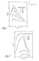
- Figure 2 is a plot of intrinsic magnetic coercivity versus substrate quench speed for alloys of neodymium and iron where neodymium comprises 25 atomic percent of the alloy.
- the samples were made and tested as in Example 1.
- boron in amounts of three and five atomic percent based on iron content greatly improved the intrinsic room temperature coercivity for these alloys. Without boron, this high iron content alloy does not show very high intrinsic coercivity ( 2.3 kOe maximum). It appears that the inclusion of even a small amount of boron can create high intrinsic magnetic coercivity in certain alloys where it would otherwise not be present.
- the Nd 0.25 (Fe 0.95 H 0.05 ) 0.75 alloy (3.75 atomic percent B) achieved an H ci of .19.7 kOe comparable, e.g., to the intrinsic coercivities of rare earth-cobalt magnets.
- Figure 3 is a plot of intrinsic room temperature coercivity as a function of quench velocity for melt spun ribbons of Nd 0.15 (Fe 1-y B y ) 0.85 alloy, wherein the fraction of boron with respect to iron was 0.03, 0.05, 0.07 and 0.09.
- the alloy was melt spun from the larger quartz tube having an orifice diameter of about 675 microns at an ejection pressure of about 20.68 kPa (3 psi) argon.
- the 0.09 also had a narrower window of quench rates over which the high coercivity magnetic phase formed.
- the inclusion of 0.03 boron increased the intrinsic coercivity of the alloy as compared to that with no boron, but the highest value of intrinsic coercivity was substantially lower than that for higher boron content alloys.
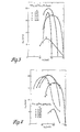
- Figure 4 is a plot of intrinsic room temperature coercivity as a function of quench velocity for melt spun alloy ribbons of neodymium, iron and boron where the Nd content was varied from 10 to 30 atomic percent and the ratio of iron to boron is held constant at 0.95 to 0.05.
- the maximum coercivity achieved for the ten.atomic weight percent neodymium alloy was only about 6 kiloOersteds.
- the maximum intrinsic coercivity achieved was about 17 kiloOersteds.
- the maximum intrinsic coercivity was at least 20 kiloOersteds.
- the optimum quench velocity for these alloys appeared to be in the 10 to 15 metre per second range.
- overquenched ribbon (V s > 20 m/s, e.g.) can be affected as will be described hereinafter to induce coercivity and remanence commensurate with optimally quenched alloy.
- Figure 6 is a demagnetization curve for melt spun Nd 0.25 (Fe 0.25 B 0.05 ) 0.75 for several different substrate chill velocities.
- Figure 7 shows demagnetization curves for melt spun Nd 0.2 (Fe 0.96 B 0.04 ) 0.8 alloy as a function of the initial magnetizing field. The curve is substantially lower for the 19 kilcOersted magnetizing field than the 45 kiloOersted field. As noted in Example 1, it is possible that higher remanence magnetization and H ci could be achieved for the subject RE-Fe-B compositions given a stronger magnetizing field strong enough to induce magnetic saturation.
- Figure 8 shows demagnetization curves for melt-spun 25 atomic percent neodymium iron alloys.
- the addition of 0.03 and 0.05 atomic fractions boron (based-on iron content) served to substantially flatten and extend the demagnetization curves for this alloy indicating higher energy products.
- Higher boron levels than those shown in Figure 7, e.g., y 0.07, result in small additional increases in coercivity but remanent magnetization drops, resulting in lowered energy product.
- boron in an amount of about 5-6 percent or less, however, stabilizes the formation of a crystalline intermetallic magnetic phase which forms into a very finely crystalline, magnetically hard microstructure during the quench. Excess boron, above 5-6 atomic percent, appears to promote the formation of magnetically soft Fe-B glasses.
- Figure 9 shows the intrinsic room temperature coercivity for Pr 0.4 Fe 0.6 and Pr 0.4 (Fe 0.95 B 0.05 ) 0.6
- the addition of a small amount of boron, here three percent of the total composition was found to improve the intrinsic coercivity of praseodymium-iron compounds from roughly 6.0 to over 16 kOe at quench velocities of about 7.5 metres per second. While neodymium-iron systems have been extensively examined, other rare earth and transition metal alloys containing boron and processed in accordance with the subject invention will exhibit permanent magnetic properties as will be described by example hereinafter.
- Figure 11 shows the energy product (BH), the magnetic remance B r and the inductive coercivity H for the several neodymium contents. The remanence, coercivity and magnetic energy product all peak at an X (the total atomic fraction of Fe and B) approximately equal to 0.86.
- An energy product of 14.1 MG'Oe was achieved which is nearly commensurate with the energy product of oriented samarium-cobalt magnets.
- Figure 13 is a scanning electron micrograph of the transverse fracture surface of a ribbon sample of the 14.1 megaGauss Oersted direct quenched alloy. The micrographs were taken near the quench surface, i.e., that surface which impinges the quench wheel in the melt-spinning process; at the center of the ribbon cross section; and at the free surface, i.e. that surface farthest from the quench wheel.
- Figure 14 shows the demagnetization behavior for the 14.1 megaGauss Oersted directly quenched magnet material.
- the relatively high remanence of about 8.2 kG contributes substantially to the high energy product (B x H).
- Figure 15 shows the effect of varying the neodymium content Nd 1-x (Fe 0.95 B 0.05 ) x alloys on the second quadrant demagnetization curve.
- V s 15 m/s.
- the inductive coercivity H is less than about 7 kiloOersteds.
- the highest remanence is achieved for neodymium contents of approximately 15 to 13.4 atomic percent.
- the near optimum composition for neodymium-iron-boron alloys contain approximately 14 percent neodymium.
- certain amounts of other rare earth metals may be substituted for neodymium which will be described hereinafter.
- Figure 16 shows demagnetization curves for melt-spun Nd 0.33 (Fe 0.95 B 0.05 ) 0.67 as a function of temperature.
- the samples were remagnetized in the pulsed 45 kOe field between temperature changes. Elevated temperatures have some adverse effect on the remanent magnetization of these materials.
- Experimental evidence indicates that approxiately 40 percent of the H ci may be lost between temperatures of 400 and 500° C. This is generally comparable to the losses experienced by mischmetal-samarium-cobalt, and SmCo 5 magnets at like temperatures. Given the high initial H ci of the present alloys, however, in many applications such losses may be.tolerated.
- Figure 17 shows demagnetization curves for melt-spun Nd 0.15 (Fe 0.95 B 0.05 ) 0.85 as a function of temperature.
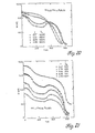
- Figure 18 shows a normalized plot of the log of intrinsic coercivity as a function of temperature for three different neodymium-iron-boron alloys. In the higher iron content alloy, intrinsic coercivity decreases less rapidly as a function of temperature than in the higher neodymium fraction containing compounds.
- Figure 20 shows magnetization dependence of melt spun Nd 0.25 (Fe 1-y B y ) 0.75 on temperature.
- the higher boron content alloys showed a dip in the magnetization curve at temperatures between about 100 and 300° Kelvin. The reason for this apparent anomaly is not currently understood.
- Figure 20 shows the effect of adding boron on Curie temperature for several neodymium-iron-boron alloys.
- Figure 21 shows the effect of varying the amount of neodymium in a neodymium-iron-boron alloy on magnetization of melt-spun samples at temperatures between 0 and 600° K. The dip between 100 and 300° Kelvin is noted in all of the curves although the high iron content alloy magnetization curve is substantially flatter in that temperature range than the higher neodymium content alloys.
- the selected samples exhibited maximum intrinsic coercivity for each boron level.
- the data X-ray were taken from finely powdered specimens over a period of several hours.
- the x-ray intensity units are on an arbitrary scale.
- the boron-free alloy X-ray spectra include Bragg reflections corresponding to the neodymium and Nd 2 Fe 17 phases, neither of which is believed to account for even a limited amount of coercivity in these alloys since the highest Curie temperature of either Nd or (Nd 2 Fe 17 ) is only 331°K.
- X-ray data indicate that the inclusion of boron in [Nd 0.15 (Fe 1-y By) 0.85 ], where 0.03 ⁇ y ⁇ 0.05, stabilizes a Nd-Fe-B intermetallic phase. This phase is believed to be responsible for the permanent magnetic properties. Its Curie temperature is well above that of any other known Nd-Fe compounds.
- Figure 23 compares the x-ray spectra of the quenched surface of an Nd 0.25 (Fe 0.95 B 0.05 ) 0.75 alloy ribbon to the free surface.
- the quenched surface is defined as that surface of the ribbon which impinges on the cooling substrate.
- the free surface is the opposite flat side of the ribbon which does not contact the cooling substrate.
- the free surface sample shows more crystallinity than the quenched surface. This may be explained by the fact that the free surface cools relatively slower than the quenched surface allowing more time for crystallographic ordering of the elements.
- ASH apparent specific heat
- X-ray data for the 15 m/s alloys are shown in Figure 16.
- X-ray patterns of the alloy before heating also indicate glass-like or amorphous behavior, exhibiting a single broad peak centered at 20 - 40°.
- Figure 26 shows typical demagnetization curves for various permanent magnet materials and lists values for their maximum energy products.
- SmCo S shows slightly better room temperature magnetic properties than the subject neodymium-iron-boron compositions. Bonded SmCo powder magnets are substantially weaker. It is believed that the subject RE-TM-B compositions could be used in high quality, high coercivity, hard magnet applications at substantially less cost than oriented SmCo 5 magnets both because of the lower cost of the constituent elements and easier processing.
- the subject hard magnet compositions have much better properties than conventional manganese-aluminium- carbon, Alnico, and ferrite magnets.
- Figure 27 shows that adding boron to ND 1-x (Fe 1-y B y ) x alloys substantially elevates the apparent Curie temperatures of the alloys. So far as practical application of the subject invention is concerned, increased Curie temperature greatly expands the possible uses for these improved hard magnet materials. For example, magnets with Curie temperatures above about 500°K (237° C) could be used in automotive underhood applications where temperatures of 150" C may be encountered.
- the data points which are blacked-in in Figure 27 particularly show the substantial increase in Curie temperature provided by adding 5 percent boron based on the iron content of the neodymium-iron melt spun alloys having less than 40 atomic percent neodymium. Like alloys without boron added to them showed a marked tendency to lowered apparent Curie temperature in alloys containing less than 40 atomic percent neodymium. That is, including boron not only elevates Curie temperature but does so at relatively lower rare earth concentrations. Thus, adding boron to suitable substantially amorphous RE-TM alloys increases intrinsic magnetic coercivity and Curie temperature at relatively high iron concentrations. These results are very desirable.
- the orifice size was approximately 670 micron metres and the ejection pressure was approximately 20-68 kPa (3.0 psi) argon. This produced overquenched alloys with virtually no hard magnetic properties.
- the line marked "no anneal" on Figure 29 shows the coercivity and remanence of the alloy as melt spun.
- the melt spun ribbon was coarsely crushed and samples weighing approximately 60 milligrams each were weighed out.
- the subsequent heating or annealing regimen was carried out under one atmosphere of . flowing argon in a Perkin-Elmer (DSC-ii) differential scanning calorimeter.
- the calorimeter was initially at room temperature with the temperature being raised at a rate of 160° K per minute up to a peak temperature of 950° K.
- the samples were cooled to room temperature at the same rate.
- the demagnetization data were taken on a magnetometer after first magnetizing the samples in the pulsed field of about 40 kiloGauss.
- Figure 29 shows second quadrant demagnetization curves for the samples as a function of how long they were maintained at the peak anneal temperature of 950° K.
- the line marked 0 min. represents the magnetic characteristics of a sample elevated to 950°K at the ramp rate of 160° K per minute and then immediately cooled to room temperature at the same rate of 160°K per minute.
- the curves for 5, 10 and 30 minutes refer to maintaining the samples at the 950° K peak temperature for periods of 5, 10 and 30 minutes at heating and cooling ramp rates of 160°K per minute.
- Figure 31 shows a plot of maximum energy product for Nd 0.135 (Fe 0.946 B 0.054 0.865 alloy.
- the circular open data points represent energy products for alloy directly quenched at the quench wheel speeds V s indicated on the X axis.
- the other data points represent the maximum energy product for alloy quenched at the V s indicated on the X-axis and then annealed in a differential scanning calorimeter at a heating and cooling ramp rate of 160°K per minute to maximum temperatures of 1000, 975 and 950°K respectively.
- a maximum energy product of 14.1 megaGauss Oersted was reached for the alloy directly quenched at an approximate wheel speed of 19 m/s.
- the alloy directly quenched at wheel speeds greater than about 20.5 metres per second shows rapidly decreasing energy product with quench wheel speed.
- At about V s 30 metres per second, the alloy as quenched has substantially no energy product.
- the solid round, triahgular and square data points represent the measured maximum energy products for the alloy quenched at the corresponding V s on the X axis after-they have been annealed to maximum temperatures of 1000, 975 and 950°K, respectively.
- the annealing steps were conducted in a differential scanning calorimeter at a heating and cooling ramp rate of 160°K per minute.
- the alloy can be overquenched and then annealed back to produce a form of the alloy with high magnetic energy product.
- the overquenched alloy i.e., in this case those melt spun ribbons quenched at a wheel speed greater than about 20 metres per second would either be completely amorphous or have crystallites or particle sizes in their microstructures smaller than optimum single magnetic domain size.
- the heating step is believed to promote the growth of the crystallites or particles within the microstructure to achieve the near optimum single domain size.
- the size of the crystallites after a rapid heating to 950°K is fairly uniform throughout the ribbon thickness.
- Figure 32 shows the second quadrant magnetization curves for the alloy of Figure 31 as directly quenched at the indicated wheel speeds.
- the alloy.that was overquenched slightly at a V 20.5 m/s also showed a decrease in ASH at 575°K but it also exhibits a sustantial increase in ASH at about 875°K It has been theorized that this peak at 875°K is associated with crystallization and growth of the magnetic phase in the alloy.
- RE 1-x (Fe 1-y B y ) x where 0.86 ⁇ x ⁇ 0.88 and 0.05 ⁇ y ⁇ 0.07 is believed to be the nominal composition of the phase primarily responsible for the hard magnetic properties.
- the preferred RE elements are neodymium and praseodymium which are virtually interchangeable with one another.
- the phase is relatively insensitive to the substitution of as much as 40 percent of other rare earth elements for Pr and Nd without its destruction.
- substantial amounts of other transition metals can be substituted for iron without destroying the phase.
- This phase is believed to be present in all compositions of suitable microstructure having hard magnetic properties. Varying the amounts of the constituents, however, changes the amount of the magnetic phase present and consequently the magnetic properties, particularly remanence.
- the slower cooling free surface shows a very slight degree of crystallization which shows up on the micrograph as a speckled appearance.
- the dot in the middle frame of the Figure is an extraneous, nonsignificant SEM feature.
- the middle and quench surfaces of the ribbon appear to be substantially amorphous, that is, discrete crystallites are not obviously distinguishable.
- the samples were cast from an orifice approximately 675 microns in size at a guench rate. of approximately 27.5 metres per second. As will be described hereinafter, the samples were heated to a peak temperature of approximately 975°K in a differential scanning calorimeter at a heating and cooling ramp rate of approximately 160°K per minute.
- the boron-free alloy y 0.0 showed substantially no coercivity after anneal and magnetization. That containing 0.03 boron exhibited a coercivity of approximately 6 kiloOersteds.
- both magnetic remanence and coercivity were substantially increased to approximately 17.5 kiloOersted and 7.5 kiloGauss, respectively.
- the coercivity increased while the magnetic remanence dropped slightly.
- both remanence and coercivity dropped with respect to the 0.07 boron content.
- praseodymium is also useful as the primary rare earth constituent of rare earth-iron-boron hard magnetic phase. It also appears to be evident that control of the time and temperature of annealing overquenched originally not permanently magnetic alloy can be controlled in such manner as to tailor the permanent magnetic properties. 3t seems that a rapid higher temperature anneal while reducing the remanence somewhat can be used to achieve very high magnetic coercivities. Dn the other hand, using lower temperature rapid anneals may tend to maximize the energy product by increasing the magnetic remanence still at coercivities greater than 15 kiloOersted.
- Figure 43 shows demagnetization curves for RE 0.135 (Fe 0.935 B 0.065 ) 0.865 alloy where RE is praseodymium, neodymium, samarium, lanthanum, cerium, terbium or dysprosium.
- RE is praseodymium, neodymium, samarium, lanthanum, cerium, terbium or dysprosium.
- Each of the alloys as .formed had less than one kiloOersted coercivity and was overquenched.
- the alloy samples were annealed in the differential scanning calorimeter at heating and cooling ramp rates of 160°K per minute to a maximum temperature of 950°K and to a minimum temperature of below about 300°K.
- Praseodymium and neodymium were the only sole rare earth elements of those tried which created annealed alloys with high coercivity remanence and energy products.
- Samarium and lanthanum showed very slight coercivities coupled with fairly steepremanence curves.
- the cerium showed some coercivity and remanence.
- Terbium exhibited low coercivity and very low remanence. While none but the pure praseodymium and neodymium alloys showed characteristics suitable for making very strong permanent magnets, the hysteresis characteristics of the other rare earths may provide magnetic materials which could be very useful for soft magnetic or other magnetic applications.
- Figure 42 shows the effect of substituting 20 percent of a different rare earth based on the amount of neodymium and such rare earth in (Nd 0.8 R 0.2 ) 0.135 (Fe 0.935 B 0.065 ) 0.865 alloys.
- Each of these 80 percent neodymium and 20 percent other rare earth alloys was melt-spun and processed as in Example 30.
- the substitution of 20 percent dysprosium, praseodymium and lanthanum created alloys with good permanent magnetic properties.
- the terbium containing alloy had a coercivity higher than could be measured by the magnetometer.
- the samarium containing alloy exhibited a remanence of over 8 kiloGauss and a coercivity of about 6 kiloOersted.
- Table 1 shows the compositions, intrinsic coercivities, magnetic remanence and energy product for the alloys shown in Examples 3 0 and 31.
- rare earth elements other than neodymium and praseodymium can be incorporated in rare earth-iron-boron alloys to create very finely crystalline permanent magnetic alloys.
- Neodymium and praseodymium metals can be mixed in suitable proportions with other rare earth elements to tailor the second quadrant magnetic characteristics for a particular application. For example, if a very high coercivity permanent magnet were desired terbium could be added to the composition. On the other hand, if magnetic remanence were the desired characteristic, it may be advantageous to add samarium.
- Figure 43 shows the demagnetization curves for Nd 0.135 (TM 0.935 B 0.065 ) 0.865 where TM are the transition metals iron, cobalt and nickel.
- TM are the transition metals iron, cobalt and nickel.
- the transition metals were not mixed with one another to form the alloy.
- the alloys were melt-spun and processed as in Example 30.
- transition metal elements Of the transition metal elements, only iron yields an alloy with very good permanent magnetic properties.
- the cobalt shows moderate intrinsic. coercivities and remanence, while the nickel containing alloy shows high coercivity but practically no magnetic remanence.
- Figure 44 shows the effect of adding 10 percent transition metal based on the amount of iron in the alloy to alloys of
- Table 11 shows the intrinsic coercivity, magnetic remanence and energy products for neodymium transition metal boron alloys. The reported values are for the best overall combination of coercivity remanence and energy product where the aim is to produce a permanent magnet. Generally, such data represent the squarest shaped second quadrant demagnetization curve.
- the preceding Examples set out preferred embodiments of the subject invention.
- the combined permanent magnetic properties of coercivity, remanence and energy product for the subject RE-Fe-B alloys are comparable to those heretofore achieved only with oriented SmCo 5 and Sm 2 Co 17 magnets. Not only are Pr, Nd and Fe less expensive than samarium and cobalt, but the subject magnetic alloys are easier and less expensive to process into permanent magnets.
- compositional range over which a major phase with the exhibited magnetic properties forms is fairly wide.
- X is preferably in the range of from about 0.5 to 0.9 and y is in the range of from about 0.005 to 0.1.
- the balance of the alloys is preferably iron. Up to about 40 percent of the iron can be replaced with cobalt with no significant loss of magnetics.
- Neodymium and praseodymium appear to be fairly intechangeable as the principal rare earth constituent.
- rare earth elements such as samarium, lanthanum, cerium, terbium and dysprosium, probably in amounts up to about 40 percent of the total rare earth content, can be incorporated with neodymium and/or praseodymium without destruction of the crystal structure of the magnetic phase or substantial loss of permanent magnetism. These rare earths can be added to purposefully modify the demagnetization curves.
- the near optimum Nd-Fe-B and Pr-Fe-B alloy nominal compositions for maximizing permanent magnetic properties are approximately RE 0.135 (Fe 0.935 B 0.065 ) 0.865 or expressed in terms of atomic fractions of the three constituent elements, RE 0.135 Fe 0.809 B 0.056 or in terms of atomic fractions normalized to boron, RE 2.4 Fe 14.4 B 1 .
- the subject samples were prepared from commercially available constituents which do contain some residual contaminants such as oxides or nitrides. Should higher purity constituents be employed, the composition, specifically the Nd to combined Fe-B ratio, would probably change slightly.
- the SEM data for the highest energy product direct quenched alloys indicate that the crystallites or particles within-the microstructure have a fairly regular shape.
- Magnetic data also suggest that the crystal structure of the stable Nd-Fe-B intermetallic phase has high symmetry. Evidence for this is the high ratio of remanent to saturation magnetization.
- Electron microprobe analysis and TEM data suggest the presence of a small amount of a second phase of unidentified composition which may also contribute to the magnetic properties.
- the directly quenched and overquenched and annealed alloy ribbons appear to be magnetically isotropic as formed. This is evidenced by the fact that the ribbon can be magnetized and demagnetized to the same strength in any direction. Bowever, if single optimum magnetic domain size powder particles or the crystallites themselves can be caused to orient along a crystallographically preferred magnetic axis, it is possible that highly magnetically anisotropic alloys having much higher magnetic energy products than are reported herein would result.
- the initial X-ray diffraction data were studied and neutron diffraction data were obtained.
- the X-ray diffraction data for melt-spun ribbon having optimum magnetic energy products have peaks which are broadened counterparts of those in the pattern from a single phase starting ingot with long range crystallographic ordering. Therefore, the Cu k-alpha d-spacing patterns for ingot alloy were used to determine the crystal structure of the major magnetic phase.
- neutron diffraction data were taken of powdered melt-spun alloy ribbon having the formula Nd 0.135 (Fe 0.935 B 0.065 ) at 673°K. This temperature is above the Curie temperature so that observed scattering is due only to nuclear and not magnetic scattering.
- a computer program based on that developed by H.M. Rietveld, Journal of Applied Crystallography, Vol. 2, No. 65 (1969) was used to synthetically generate neutron diffraction data assuming different atomic positions of the Nd, Fe and B atoms.
- Figure 46(a) displays observed neutron diffraction data;
- Figure 46(b) shows the calculated spectrum which best corresponds with the high temperature neutron data;
- Figure 46(c) shows the difference between the observed and calculated data.
- the goodness-of-fit index is 11.7 percent while the statistical uncertainty is 8.8 percent.
- the formula per unit cell associated with Figure 46(b) is Nd 8 Fe 56 B 4 and the calculated density is 7.6 g/cm 3 which agrees with the measured density. This would mean that the atomic formula for the major phase of the magnetic alloys of this invention would be Nd 2 Fe 14 B 1 .
- the calculated data were sensitive to both the number and position of the boron atoms.
- Figure 49 shows the layers of iron atoms at locations z - 0.25 and 0.75.
- Figure 52 shows a view of one entire unit cell. The relative length of the c axis is exaggerated to emphasize the puckering of the hexagonal iron meshes.
- the preferred magnetic axis i.e. that axis of alignment which yields the highest magnetic anisotropy, is the crystallographic c axis.
- Rapid solidification of the alloy is believed to create a condition wherein the individual crystallites or particles in the alloy microstructure are about the same size or smaller than optimum single magnetic domain size.
- the optimum magnetic domain size is believed to about 40 - 50 nanometers average diameter. Alloys having crystallites in the size range of about 20 - 400 nanometers exhibit permanent magnetic properties. Alloys having smaller crystallites ( ⁇ 20 nanometers) may be heated to promote crystallite growth to optimum magnetic domain size.
- the paths by which optimum crystallite size alloy can be made are (1) direct quench from the melt by means of a controlled quench rate process such as melt spinning, or (2) overquench to a microstructure having smaller than optimum single domain size crystallites followed by a heating process to promote crystallite growth to near optimum single magnetic domain size.
- the major phase of the magnetic alloys has a tetragonal crystal structure where the length of the a axis is about 8.78 angstroms and the c axis is about 12.18 angstroms.
- the composition of this phase is RE 2 Fe 14 B 1 as determined by neutron diffraction analysis. Efficient and economical means of making the subject alloys in forms adapted for the production of a new breed of permanent magnets have also been discovered. It is expected that these magnets will find application in many industrial environments.
Landscapes
- Chemical & Material Sciences (AREA)
- Engineering & Computer Science (AREA)
- Crystallography & Structural Chemistry (AREA)
- Inorganic Chemistry (AREA)
- Power Engineering (AREA)
- Materials Engineering (AREA)
- Mechanical Engineering (AREA)
- Metallurgy (AREA)
- Organic Chemistry (AREA)
- Hard Magnetic Materials (AREA)
Applications Claiming Priority (2)
| Application Number | Priority Date | Filing Date | Title |
|---|---|---|---|
| US54472883A | 1983-10-26 | 1983-10-26 | |
| US544728 | 1983-10-26 |
Publications (2)
| Publication Number | Publication Date |
|---|---|
| EP0144112A1 true EP0144112A1 (de) | 1985-06-12 |
| EP0144112B1 EP0144112B1 (de) | 1989-09-27 |
Family
ID=24173341
Family Applications (1)
| Application Number | Title | Priority Date | Filing Date |
|---|---|---|---|
| EP84300741A Expired EP0144112B1 (de) | 1983-10-26 | 1984-02-07 | Magnetische Legierungen mit hohem Energieprodukt aus seltenen Erden, Übergangsmetallen und Bor |
Country Status (5)
| Country | Link |
|---|---|
| EP (1) | EP0144112B1 (de) |
| BR (1) | BR8400917A (de) |
| DE (1) | DE3479940D1 (de) |
| MX (1) | MX167656B (de) |
| ZA (1) | ZA841312B (de) |
Cited By (15)
| Publication number | Priority date | Publication date | Assignee | Title |
|---|---|---|---|---|
| DE3626406A1 (de) * | 1985-08-13 | 1987-02-26 | Seiko Epson Corp | Verfahren zur herstellung von dauermagneten auf der basis von seltenerdmetallen |
| EP0229946A1 (de) * | 1986-01-10 | 1987-07-29 | Ovonic Synthetic Materials Company, Inc. | Permanentmagnetische Legierung |
| EP0231620A3 (en) * | 1986-01-29 | 1988-01-27 | General Motors Corporation | Permanent magnet manufacture from very low coercivity crystalline rare earth-transition metal-boron alloy |
| EP0260746A1 (de) * | 1986-09-17 | 1988-03-23 | Koninklijke Philips Electronics N.V. | Verfahren zur Herstellung von Spänen aus magnetischem Material mit Vorzugsrichtung der Kristallite, Späne und Magnete, die daraus hergestellt sind |
| EP0261292A3 (en) * | 1986-07-28 | 1988-07-27 | Crucible Materials Corporation | Method of producing fully dense permanent magnet alloy article and article produced thereby |
| DE3709138A1 (de) * | 1987-03-20 | 1988-09-29 | Siemens Ag | Verfahren zur herstellung eines magnetischen werkstoffes aus pulverfoermigen ausgangskomponenten |
| EP0284832A1 (de) * | 1987-03-20 | 1988-10-05 | Siemens Aktiengesellschaft | Verfahren zur Herstellung eines anisotropen Magnetwerkstoffes auf Basis von Fe, B und einem Selten-Erd-Metall |
| US4844751A (en) * | 1986-03-27 | 1989-07-04 | Siemens Aktiengesellschaft | Method for manufacturing a permanent magnet material from starting components in powder form |
| EP0302947A4 (de) * | 1987-03-02 | 1990-03-08 | Seiko Epson Corp | Seltene-erden-eisen-typ-dauermagnet und sein herstellungsverfahren. |
| DE3832472A1 (de) * | 1988-09-23 | 1990-03-29 | Siemens Ag | Verfahren zur herstellung eines werkstoffes mit einer hartmagnetischen phase aus pulverfoermigen ausgangskomponenten |
| US5213631A (en) * | 1987-03-02 | 1993-05-25 | Seiko Epson Corporation | Rare earth-iron system permanent magnet and process for producing the same |
| US5538565A (en) * | 1985-08-13 | 1996-07-23 | Seiko Epson Corporation | Rare earth cast alloy permanent magnets and methods of preparation |
| GB2308384A (en) * | 1995-12-21 | 1997-06-25 | Univ Hull | Magnetic materials |
| US6136099A (en) * | 1985-08-13 | 2000-10-24 | Seiko Epson Corporation | Rare earth-iron series permanent magnets and method of preparation |
| US10861629B1 (en) * | 2017-03-03 | 2020-12-08 | Apple Inc. | Solid state deposition of magnetizable materials |
Families Citing this family (1)
| Publication number | Priority date | Publication date | Assignee | Title |
|---|---|---|---|---|
| CN103668007B (zh) * | 2013-12-19 | 2015-08-19 | 南京信息工程大学 | 一种具有高饱和磁感应强度微晶合金薄带及制备方法 |
Citations (2)
| Publication number | Priority date | Publication date | Assignee | Title |
|---|---|---|---|---|
| GB2100286A (en) * | 1981-06-16 | 1982-12-22 | Gen Motors Corp | High coercivity rare earth-transition metal magnets |
| US4374665A (en) * | 1981-10-23 | 1983-02-22 | The United States Of America As Represented By The Secretary Of The Navy | Magnetostrictive devices |
Family Cites Families (2)
| Publication number | Priority date | Publication date | Assignee | Title |
|---|---|---|---|---|
| CA1316375C (en) * | 1982-08-21 | 1993-04-20 | Masato Sagawa | Magnetic materials and permanent magnets |
| DE3379084D1 (en) * | 1982-09-27 | 1989-03-02 | Sumitomo Spec Metals | Permanently magnetizable alloys, magnetic materials and permanent magnets comprising febr or (fe,co)br (r=vave earth) |
-
1984
- 1984-02-07 DE DE8484300741T patent/DE3479940D1/de not_active Expired
- 1984-02-07 EP EP84300741A patent/EP0144112B1/de not_active Expired
- 1984-02-22 ZA ZA841312A patent/ZA841312B/xx unknown
- 1984-02-28 BR BR8400917A patent/BR8400917A/pt not_active IP Right Cessation
- 1984-03-01 MX MX026602A patent/MX167656B/es unknown
Patent Citations (2)
| Publication number | Priority date | Publication date | Assignee | Title |
|---|---|---|---|---|
| GB2100286A (en) * | 1981-06-16 | 1982-12-22 | Gen Motors Corp | High coercivity rare earth-transition metal magnets |
| US4374665A (en) * | 1981-10-23 | 1983-02-22 | The United States Of America As Represented By The Secretary Of The Navy | Magnetostrictive devices |
Non-Patent Citations (3)
| Title |
|---|
| IEEE TRANSACTIONS ON MAGNETICS, vol. MAG-18, no. 6, November 1982 New York J. CROAT "Permanent Magnet Properties of Rapidly quenched Rare Earth-Iron Alloys" Seiten 1442-1447 seite 1443, linke spalte, paragraph 2 seite 1444, linke spalte, paragraph 3 fig. 3-5 * |
| IEEE TRANSACTIONS ON MAGNETICS, vol. MAG-18, no. 6, November 1982 New York N. KOON et al. "Composition Dependence of the Coercive Force and Microstructure of Crystallized Amorphous(Fex-B1-x)0.9 Tb0.05La0.05 Seiten 1448-1450 seite 1448, linke spalte, paragraph 3 seite 1449, linke spalte, paragraph 1 seite 1450, rechte spalte, paragraph 1 fig. 1-4b * |
| J. APPL. PHYS., vol. 53, no. 3, March 1982, New York L. KABACOFF et al. "Thermal and Magnetic Properties of Amorphous Prx (Fe0.8B0.2)1-x" Seiten 2255-2257 seite 2255, linke spalte, paragraph 1 seite 2256, linke spalte, paragraph 1 fig. 1-3 * |
Cited By (21)
| Publication number | Priority date | Publication date | Assignee | Title |
|---|---|---|---|---|
| US5560784A (en) * | 1985-08-13 | 1996-10-01 | Seiko Epson Corporation | Rare earth cast alloy permanent magnets and methods of preparation |
| DE3626406A1 (de) * | 1985-08-13 | 1987-02-26 | Seiko Epson Corp | Verfahren zur herstellung von dauermagneten auf der basis von seltenerdmetallen |
| US6136099A (en) * | 1985-08-13 | 2000-10-24 | Seiko Epson Corporation | Rare earth-iron series permanent magnets and method of preparation |
| US5597425A (en) * | 1985-08-13 | 1997-01-28 | Seiko Epson Corporation | Rare earth cast alloy permanent magnets and methods of preparation |
| US5538565A (en) * | 1985-08-13 | 1996-07-23 | Seiko Epson Corporation | Rare earth cast alloy permanent magnets and methods of preparation |
| US5565043A (en) * | 1985-08-13 | 1996-10-15 | Seiko Epson Corporation | Rare earth cast alloy permanent magnets and methods of preparation |
| EP0229946A1 (de) * | 1986-01-10 | 1987-07-29 | Ovonic Synthetic Materials Company, Inc. | Permanentmagnetische Legierung |
| US4921551A (en) * | 1986-01-29 | 1990-05-01 | General Motors Corporation | Permanent magnet manufacture from very low coercivity crystalline rare earth-transition metal-boron alloy |
| EP0231620A3 (en) * | 1986-01-29 | 1988-01-27 | General Motors Corporation | Permanent magnet manufacture from very low coercivity crystalline rare earth-transition metal-boron alloy |
| US4844751A (en) * | 1986-03-27 | 1989-07-04 | Siemens Aktiengesellschaft | Method for manufacturing a permanent magnet material from starting components in powder form |
| EP0261292A3 (en) * | 1986-07-28 | 1988-07-27 | Crucible Materials Corporation | Method of producing fully dense permanent magnet alloy article and article produced thereby |
| EP0260746A1 (de) * | 1986-09-17 | 1988-03-23 | Koninklijke Philips Electronics N.V. | Verfahren zur Herstellung von Spänen aus magnetischem Material mit Vorzugsrichtung der Kristallite, Späne und Magnete, die daraus hergestellt sind |
| US5213631A (en) * | 1987-03-02 | 1993-05-25 | Seiko Epson Corporation | Rare earth-iron system permanent magnet and process for producing the same |
| EP0302947A4 (de) * | 1987-03-02 | 1990-03-08 | Seiko Epson Corp | Seltene-erden-eisen-typ-dauermagnet und sein herstellungsverfahren. |
| DE3709138A1 (de) * | 1987-03-20 | 1988-09-29 | Siemens Ag | Verfahren zur herstellung eines magnetischen werkstoffes aus pulverfoermigen ausgangskomponenten |
| US4854979A (en) * | 1987-03-20 | 1989-08-08 | Siemens Aktiengesellschaft | Method for the manufacture of an anisotropic magnet material on the basis of Fe, B and a rare-earth metal |
| EP0284832A1 (de) * | 1987-03-20 | 1988-10-05 | Siemens Aktiengesellschaft | Verfahren zur Herstellung eines anisotropen Magnetwerkstoffes auf Basis von Fe, B und einem Selten-Erd-Metall |
| DE3832472A1 (de) * | 1988-09-23 | 1990-03-29 | Siemens Ag | Verfahren zur herstellung eines werkstoffes mit einer hartmagnetischen phase aus pulverfoermigen ausgangskomponenten |
| GB2308384A (en) * | 1995-12-21 | 1997-06-25 | Univ Hull | Magnetic materials |
| GB2308384B (en) * | 1995-12-21 | 1999-09-15 | Univ Hull | Magnetic materials |
| US10861629B1 (en) * | 2017-03-03 | 2020-12-08 | Apple Inc. | Solid state deposition of magnetizable materials |
Also Published As
| Publication number | Publication date |
|---|---|
| EP0144112B1 (de) | 1989-09-27 |
| DE3479940D1 (en) | 1989-11-02 |
| MX167656B (es) | 1993-04-01 |
| BR8400917A (pt) | 1985-06-11 |
| ZA841312B (en) | 1985-09-25 |
Similar Documents
| Publication | Publication Date | Title |
|---|---|---|
| US4802931A (en) | High energy product rare earth-iron magnet alloys | |
| US5172751A (en) | High energy product rare earth-iron magnet alloys | |
| US4851058A (en) | High energy product rare earth-iron magnet alloys | |
| Croat et al. | Pr‐Fe and Nd‐Fe‐based materials: A new class of high‐performance permanent magnets | |
| CA1202864A (en) | High coercivity rare earth-iron magnets | |
| JPS609852A (ja) | 高エネルギ−積の稀土類−鉄磁石合金 | |
| US4898625A (en) | Method for producing a rare earth metal-iron-boron permanent magnet by use of a rapidly-quenched alloy powder | |
| EP0144112B1 (de) | Magnetische Legierungen mit hohem Energieprodukt aus seltenen Erden, Übergangsmetallen und Bor | |
| US4767474A (en) | Isotropic magnets and process for producing same | |
| US5750044A (en) | Magnet and bonded magnet | |
| US4867785A (en) | Method of forming alloy particulates having controlled submicron crystallite size distributions | |
| US6413327B1 (en) | Nitride type, rare earth magnet materials and bonded magnets formed therefrom | |
| KR20030025925A (ko) | 복수의 강자성상을 포함하는 영구자석 및 그 제조방법 | |
| US5474623A (en) | Magnetically anisotropic spherical powder and method of making same | |
| JPH09170055A (ja) | 希土類磁石用合金及びその製造方法並びに永久磁石の製造方法 | |
| KR960008185B1 (ko) | 희토류-철계 영구자석 및 이의 제조방법 | |
| EP0680054B1 (de) | SE-Fe-B Magneten und ihrer Herstellungsverfahren | |
| US5395459A (en) | Method for forming samarium-iron-nitride magnet alloys | |
| US5174362A (en) | High-energy product rare earth-iron magnet alloys | |
| US5056585A (en) | High energy product rare earth-iron magnet alloys | |
| JP3264664B1 (ja) | 複数の強磁性相を有する永久磁石およびその製造方法 | |
| JP3560387B2 (ja) | 磁性材料とその製造法 | |
| CA1319034C (en) | High energy product rare earth-iron magnet alloys | |
| JPH07188704A (ja) | 希土類永久磁石用合金粉末及びその製造法 | |
| JPH062929B2 (ja) | 永久磁石材料 |
Legal Events
| Date | Code | Title | Description |
|---|---|---|---|
| PUAI | Public reference made under article 153(3) epc to a published international application that has entered the european phase |
Free format text: ORIGINAL CODE: 0009012 |
|
| AK | Designated contracting states |
Designated state(s): DE FR GB IT SE |
|
| 17P | Request for examination filed |
Effective date: 19850923 |
|
| 17Q | First examination report despatched |
Effective date: 19870805 |
|
| GRAA | (expected) grant |
Free format text: ORIGINAL CODE: 0009210 |
|
| AK | Designated contracting states |
Kind code of ref document: B1 Designated state(s): DE FR GB IT SE |
|
| ITF | It: translation for a ep patent filed | ||
| REF | Corresponds to: |
Ref document number: 3479940 Country of ref document: DE Date of ref document: 19891102 |
|
| ET | Fr: translation filed | ||
| PLBE | No opposition filed within time limit |
Free format text: ORIGINAL CODE: 0009261 |
|
| STAA | Information on the status of an ep patent application or granted ep patent |
Free format text: STATUS: NO OPPOSITION FILED WITHIN TIME LIMIT |
|
| 26N | No opposition filed | ||
| ITTA | It: last paid annual fee | ||
| EAL | Se: european patent in force in sweden |
Ref document number: 84300741.0 |
|
| PGFP | Annual fee paid to national office [announced via postgrant information from national office to epo] |
Ref country code: SE Payment date: 19990114 Year of fee payment: 16 |
|
| PG25 | Lapsed in a contracting state [announced via postgrant information from national office to epo] |
Ref country code: SE Free format text: LAPSE BECAUSE OF NON-PAYMENT OF DUE FEES Effective date: 20000208 |
|
| EUG | Se: european patent has lapsed |
Ref document number: 84300741.0 |
|
| REG | Reference to a national code |
Ref country code: GB Ref legal event code: 732E |
|
| REG | Reference to a national code |
Ref country code: FR Ref legal event code: TP |
|
| REG | Reference to a national code |
Ref country code: GB Ref legal event code: IF02 |
|
| PGFP | Annual fee paid to national office [announced via postgrant information from national office to epo] |
Ref country code: GB Payment date: 20030205 Year of fee payment: 20 |
|
| PGFP | Annual fee paid to national office [announced via postgrant information from national office to epo] |
Ref country code: FR Payment date: 20030210 Year of fee payment: 20 |
|
| PGFP | Annual fee paid to national office [announced via postgrant information from national office to epo] |
Ref country code: DE Payment date: 20030220 Year of fee payment: 20 |
|
| PG25 | Lapsed in a contracting state [announced via postgrant information from national office to epo] |
Ref country code: GB Free format text: LAPSE BECAUSE OF EXPIRATION OF PROTECTION Effective date: 20040206 |
|
| REG | Reference to a national code |
Ref country code: GB Ref legal event code: PE20 |