EP0145406B1 - Mikrostrukturen - Google Patents
Mikrostrukturen Download PDFInfo
- Publication number
- EP0145406B1 EP0145406B1 EP84308230A EP84308230A EP0145406B1 EP 0145406 B1 EP0145406 B1 EP 0145406B1 EP 84308230 A EP84308230 A EP 84308230A EP 84308230 A EP84308230 A EP 84308230A EP 0145406 B1 EP0145406 B1 EP 0145406B1
- Authority
- EP
- European Patent Office
- Prior art keywords
- substrate
- cells
- cell
- discontinuities
- adhesion
- Prior art date
- Legal status (The legal status is an assumption and is not a legal conclusion. Google has not performed a legal analysis and makes no representation as to the accuracy of the status listed.)
- Expired - Lifetime
Links
- 239000000758 substrate Substances 0.000 claims abstract description 62
- 230000021164 cell adhesion Effects 0.000 claims abstract description 27
- 239000007787 solid Substances 0.000 claims abstract description 6
- 210000004027 cell Anatomy 0.000 claims description 53
- 239000000463 material Substances 0.000 claims description 20
- 238000000034 method Methods 0.000 claims description 14
- 239000004020 conductor Substances 0.000 claims description 12
- 210000002569 neuron Anatomy 0.000 claims description 8
- 230000015572 biosynthetic process Effects 0.000 claims description 7
- 210000002950 fibroblast Anatomy 0.000 claims description 3
- 230000002401 inhibitory effect Effects 0.000 claims description 3
- 239000004065 semiconductor Substances 0.000 claims description 3
- 230000002708 enhancing effect Effects 0.000 claims 1
- 210000004498 neuroglial cell Anatomy 0.000 claims 1
- 239000004642 Polyimide Substances 0.000 description 14
- 229910052751 metal Inorganic materials 0.000 description 14
- 239000002184 metal Substances 0.000 description 14
- 229920001721 polyimide Polymers 0.000 description 14
- VYPSYNLAJGMNEJ-UHFFFAOYSA-N Silicium dioxide Chemical compound O=[Si]=O VYPSYNLAJGMNEJ-UHFFFAOYSA-N 0.000 description 10
- 239000010410 layer Substances 0.000 description 10
- PCHJSUWPFVWCPO-UHFFFAOYSA-N gold Chemical compound [Au] PCHJSUWPFVWCPO-UHFFFAOYSA-N 0.000 description 8
- 229910052737 gold Inorganic materials 0.000 description 8
- 239000010931 gold Substances 0.000 description 8
- 229920002120 photoresistant polymer Polymers 0.000 description 8
- 239000000523 sample Substances 0.000 description 8
- 239000004793 Polystyrene Substances 0.000 description 6
- 229920002223 polystyrene Polymers 0.000 description 6
- 238000010884 ion-beam technique Methods 0.000 description 5
- 239000002609 medium Substances 0.000 description 5
- OKTJSMMVPCPJKN-UHFFFAOYSA-N Carbon Chemical compound [C] OKTJSMMVPCPJKN-UHFFFAOYSA-N 0.000 description 4
- 239000004411 aluminium Substances 0.000 description 4
- 229910052782 aluminium Inorganic materials 0.000 description 4
- XAGFODPZIPBFFR-UHFFFAOYSA-N aluminium Chemical compound [Al] XAGFODPZIPBFFR-UHFFFAOYSA-N 0.000 description 4
- QVGXLLKOCUKJST-UHFFFAOYSA-N atomic oxygen Chemical compound [O] QVGXLLKOCUKJST-UHFFFAOYSA-N 0.000 description 4
- 239000011521 glass Substances 0.000 description 4
- 239000001301 oxygen Substances 0.000 description 4
- 229910052760 oxygen Inorganic materials 0.000 description 4
- -1 polytetrafluoroethylene Polymers 0.000 description 4
- 210000002966 serum Anatomy 0.000 description 4
- 239000000377 silicon dioxide Substances 0.000 description 4
- 239000004952 Polyamide Substances 0.000 description 3
- YXFVVABEGXRONW-UHFFFAOYSA-N Toluene Chemical compound CC1=CC=CC=C1 YXFVVABEGXRONW-UHFFFAOYSA-N 0.000 description 3
- 229910052799 carbon Inorganic materials 0.000 description 3
- 229920002678 cellulose Polymers 0.000 description 3
- 235000010980 cellulose Nutrition 0.000 description 3
- 238000003486 chemical etching Methods 0.000 description 3
- 210000004292 cytoskeleton Anatomy 0.000 description 3
- 238000010894 electron beam technology Methods 0.000 description 3
- 238000005530 etching Methods 0.000 description 3
- 125000002887 hydroxy group Chemical group [H]O* 0.000 description 3
- 238000004519 manufacturing process Methods 0.000 description 3
- 229920002647 polyamide Polymers 0.000 description 3
- 239000000243 solution Substances 0.000 description 3
- KDLHZDBZIXYQEI-UHFFFAOYSA-N Palladium Chemical compound [Pd] KDLHZDBZIXYQEI-UHFFFAOYSA-N 0.000 description 2
- 239000004743 Polypropylene Substances 0.000 description 2
- FAPWRFPIFSIZLT-UHFFFAOYSA-M Sodium chloride Chemical compound [Na+].[Cl-] FAPWRFPIFSIZLT-UHFFFAOYSA-M 0.000 description 2
- 239000000654 additive Substances 0.000 description 2
- 230000000996 additive effect Effects 0.000 description 2
- 244000309466 calf Species 0.000 description 2
- 210000002421 cell wall Anatomy 0.000 description 2
- 239000001913 cellulose Substances 0.000 description 2
- 239000011248 coating agent Substances 0.000 description 2
- 238000000576 coating method Methods 0.000 description 2
- 230000000694 effects Effects 0.000 description 2
- 239000000835 fiber Substances 0.000 description 2
- 239000005350 fused silica glass Substances 0.000 description 2
- 229910002804 graphite Inorganic materials 0.000 description 2
- 239000010439 graphite Substances 0.000 description 2
- 239000001963 growth medium Substances 0.000 description 2
- 230000003993 interaction Effects 0.000 description 2
- 229910044991 metal oxide Inorganic materials 0.000 description 2
- 150000004706 metal oxides Chemical class 0.000 description 2
- 239000000203 mixture Substances 0.000 description 2
- 239000004033 plastic Substances 0.000 description 2
- 229920003023 plastic Polymers 0.000 description 2
- BASFCYQUMIYNBI-UHFFFAOYSA-N platinum Chemical compound [Pt] BASFCYQUMIYNBI-UHFFFAOYSA-N 0.000 description 2
- 229920000193 polymethacrylate Polymers 0.000 description 2
- 229920000098 polyolefin Polymers 0.000 description 2
- 229920001155 polypropylene Polymers 0.000 description 2
- 230000001737 promoting effect Effects 0.000 description 2
- 230000001681 protective effect Effects 0.000 description 2
- 239000011780 sodium chloride Substances 0.000 description 2
- XAGFODPZIPBFFR-NJFSPNSNSA-N Aluminium-29 Chemical compound [29Al] XAGFODPZIPBFFR-NJFSPNSNSA-N 0.000 description 1
- JBRZTFJDHDCESZ-UHFFFAOYSA-N AsGa Chemical compound [As]#[Ga] JBRZTFJDHDCESZ-UHFFFAOYSA-N 0.000 description 1
- RYGMFSIKBFXOCR-UHFFFAOYSA-N Copper Chemical compound [Cu] RYGMFSIKBFXOCR-UHFFFAOYSA-N 0.000 description 1
- 229910001218 Gallium arsenide Inorganic materials 0.000 description 1
- ZOKXTWBITQBERF-UHFFFAOYSA-N Molybdenum Chemical compound [Mo] ZOKXTWBITQBERF-UHFFFAOYSA-N 0.000 description 1
- 108010025020 Nerve Growth Factor Proteins 0.000 description 1
- 102000015336 Nerve Growth Factor Human genes 0.000 description 1
- 239000000020 Nitrocellulose Substances 0.000 description 1
- 229910019142 PO4 Inorganic materials 0.000 description 1
- RTAQQCXQSZGOHL-UHFFFAOYSA-N Titanium Chemical compound [Ti] RTAQQCXQSZGOHL-UHFFFAOYSA-N 0.000 description 1
- FJWGYAHXMCUOOM-QHOUIDNNSA-N [(2s,3r,4s,5r,6r)-2-[(2r,3r,4s,5r,6s)-4,5-dinitrooxy-2-(nitrooxymethyl)-6-[(2r,3r,4s,5r,6s)-4,5,6-trinitrooxy-2-(nitrooxymethyl)oxan-3-yl]oxyoxan-3-yl]oxy-3,5-dinitrooxy-6-(nitrooxymethyl)oxan-4-yl] nitrate Chemical compound O([C@@H]1O[C@@H]([C@H]([C@H](O[N+]([O-])=O)[C@H]1O[N+]([O-])=O)O[C@H]1[C@@H]([C@@H](O[N+]([O-])=O)[C@H](O[N+]([O-])=O)[C@@H](CO[N+]([O-])=O)O1)O[N+]([O-])=O)CO[N+](=O)[O-])[C@@H]1[C@@H](CO[N+]([O-])=O)O[C@@H](O[N+]([O-])=O)[C@H](O[N+]([O-])=O)[C@H]1O[N+]([O-])=O FJWGYAHXMCUOOM-QHOUIDNNSA-N 0.000 description 1
- 238000007792 addition Methods 0.000 description 1
- 230000002411 adverse Effects 0.000 description 1
- PNEYBMLMFCGWSK-UHFFFAOYSA-N aluminium oxide Inorganic materials [O-2].[O-2].[O-2].[Al+3].[Al+3] PNEYBMLMFCGWSK-UHFFFAOYSA-N 0.000 description 1
- 125000003277 amino group Chemical group 0.000 description 1
- 239000007864 aqueous solution Substances 0.000 description 1
- DTYHPIGVFDJOMR-UHFFFAOYSA-N argon iron Chemical compound [Ar].[Fe].[Fe].[Fe].[Fe].[Fe].[Fe].[Fe].[Fe].[Fe] DTYHPIGVFDJOMR-UHFFFAOYSA-N 0.000 description 1
- 238000003491 array Methods 0.000 description 1
- 239000012620 biological material Substances 0.000 description 1
- 210000000988 bone and bone Anatomy 0.000 description 1
- 210000004556 brain Anatomy 0.000 description 1
- 210000003837 chick embryo Anatomy 0.000 description 1
- 238000010276 construction Methods 0.000 description 1
- 238000011109 contamination Methods 0.000 description 1
- 229910052802 copper Inorganic materials 0.000 description 1
- 239000010949 copper Substances 0.000 description 1
- 210000001787 dendrite Anatomy 0.000 description 1
- 238000000151 deposition Methods 0.000 description 1
- 238000009713 electroplating Methods 0.000 description 1
- 239000003822 epoxy resin Substances 0.000 description 1
- 238000001704 evaporation Methods 0.000 description 1
- 230000008020 evaporation Effects 0.000 description 1
- 238000005194 fractionation Methods 0.000 description 1
- 239000007792 gaseous phase Substances 0.000 description 1
- 230000002518 glial effect Effects 0.000 description 1
- LNEPOXFFQSENCJ-UHFFFAOYSA-N haloperidol Chemical compound C1CC(O)(C=2C=CC(Cl)=CC=2)CCN1CCCC(=O)C1=CC=C(F)C=C1 LNEPOXFFQSENCJ-UHFFFAOYSA-N 0.000 description 1
- 229930195733 hydrocarbon Natural products 0.000 description 1
- 150000002430 hydrocarbons Chemical class 0.000 description 1
- 238000007689 inspection Methods 0.000 description 1
- 238000009413 insulation Methods 0.000 description 1
- 239000012212 insulator Substances 0.000 description 1
- 229910052741 iridium Inorganic materials 0.000 description 1
- GKOZUEZYRPOHIO-UHFFFAOYSA-N iridium atom Chemical compound [Ir] GKOZUEZYRPOHIO-UHFFFAOYSA-N 0.000 description 1
- WABPQHHGFIMREM-UHFFFAOYSA-N lead(0) Chemical compound [Pb] WABPQHHGFIMREM-UHFFFAOYSA-N 0.000 description 1
- 239000007791 liquid phase Substances 0.000 description 1
- 210000004698 lymphocyte Anatomy 0.000 description 1
- 210000002540 macrophage Anatomy 0.000 description 1
- 150000002739 metals Chemical class 0.000 description 1
- 238000003801 milling Methods 0.000 description 1
- 239000011733 molybdenum Substances 0.000 description 1
- 229910000476 molybdenum oxide Inorganic materials 0.000 description 1
- 229940053128 nerve growth factor Drugs 0.000 description 1
- 229920001220 nitrocellulos Polymers 0.000 description 1
- 231100000252 nontoxic Toxicity 0.000 description 1
- 230000003000 nontoxic effect Effects 0.000 description 1
- 239000011368 organic material Substances 0.000 description 1
- BPUBBGLMJRNUCC-UHFFFAOYSA-N oxygen(2-);tantalum(5+) Chemical class [O-2].[O-2].[O-2].[O-2].[O-2].[Ta+5].[Ta+5] BPUBBGLMJRNUCC-UHFFFAOYSA-N 0.000 description 1
- 229910052763 palladium Inorganic materials 0.000 description 1
- 239000012188 paraffin wax Substances 0.000 description 1
- 238000002135 phase contrast microscopy Methods 0.000 description 1
- 239000010452 phosphate Substances 0.000 description 1
- 238000007747 plating Methods 0.000 description 1
- 229910052697 platinum Inorganic materials 0.000 description 1
- 231100000572 poisoning Toxicity 0.000 description 1
- 230000000607 poisoning effect Effects 0.000 description 1
- 229920000647 polyepoxide Polymers 0.000 description 1
- 229920001296 polysiloxane Polymers 0.000 description 1
- 239000004810 polytetrafluoroethylene Substances 0.000 description 1
- 229920001343 polytetrafluoroethylene Polymers 0.000 description 1
- 229920002689 polyvinyl acetate Polymers 0.000 description 1
- 239000011118 polyvinyl acetate Substances 0.000 description 1
- 102000004169 proteins and genes Human genes 0.000 description 1
- 108090000623 proteins and genes Proteins 0.000 description 1
- 230000005855 radiation Effects 0.000 description 1
- 230000000717 retained effect Effects 0.000 description 1
- 230000001953 sensory effect Effects 0.000 description 1
- 238000000926 separation method Methods 0.000 description 1
- 239000011343 solid material Substances 0.000 description 1
- 239000002904 solvent Substances 0.000 description 1
- 239000000126 substance Substances 0.000 description 1
- 239000002344 surface layer Substances 0.000 description 1
- 239000000725 suspension Substances 0.000 description 1
- 229910001936 tantalum oxide Inorganic materials 0.000 description 1
- 210000001519 tissue Anatomy 0.000 description 1
- 239000010936 titanium Substances 0.000 description 1
- OGIDPMRJRNCKJF-UHFFFAOYSA-N titanium oxide Inorganic materials [Ti]=O OGIDPMRJRNCKJF-UHFFFAOYSA-N 0.000 description 1
- 238000012876 topography Methods 0.000 description 1
- 239000012588 trypsin Substances 0.000 description 1
- 238000001771 vacuum deposition Methods 0.000 description 1
Images

Classifications
-
- C—CHEMISTRY; METALLURGY
- C12—BIOCHEMISTRY; BEER; SPIRITS; WINE; VINEGAR; MICROBIOLOGY; ENZYMOLOGY; MUTATION OR GENETIC ENGINEERING
- C12M—APPARATUS FOR ENZYMOLOGY OR MICROBIOLOGY; APPARATUS FOR CULTURING MICROORGANISMS FOR PRODUCING BIOMASS, FOR GROWING CELLS OR FOR OBTAINING FERMENTATION OR METABOLIC PRODUCTS, i.e. BIOREACTORS OR FERMENTERS
- C12M25/00—Means for supporting, enclosing or fixing the microorganisms, e.g. immunocoatings
- C12M25/06—Plates; Walls; Drawers; Multilayer plates
- C12M25/08—Plates; Walls; Drawers; Multilayer plates electrically charged
-
- C—CHEMISTRY; METALLURGY
- C12—BIOCHEMISTRY; BEER; SPIRITS; WINE; VINEGAR; MICROBIOLOGY; ENZYMOLOGY; MUTATION OR GENETIC ENGINEERING
- C12M—APPARATUS FOR ENZYMOLOGY OR MICROBIOLOGY; APPARATUS FOR CULTURING MICROORGANISMS FOR PRODUCING BIOMASS, FOR GROWING CELLS OR FOR OBTAINING FERMENTATION OR METABOLIC PRODUCTS, i.e. BIOREACTORS OR FERMENTERS
- C12M23/00—Constructional details, e.g. recesses, hinges
- C12M23/20—Material Coatings
Definitions
- This invention relates to bio-mechanical microstructures and the formation thereof.
- the present invention provides a method of locating a plurality of cells in a predetermined spatial disposition relative to each other on a solid non-biological substrate, which method comprises providing on an extended generally planar surface of said substrate a plurality of elongate surface discontinuities at least partly defining cell adhesion enhanced and/or cell-adhesion orienting zones having a width of from 0.2 to 20 micrometres in a predetermined relation to each other and substantially spaced apart from each other and bringing a plurality of said cells in a physiologically acceptable medium into contact with said substrate surface.
- the present invention also extends to a bio- mechanical micro-structure comprising a solid non-biological substrate with an extended generally planar surface on which surface is provided a plurality of elongate surface discontinuities at least partly defining cell-adhesion enhanced and/or cell-adhesion orientating zones having a width of from 0.2 to 20 micrometres in a predetermined relation to each other and substantially spaced apart from each other with a plurality of cells attached to said zones of said surface.
- the present invention provides a solid non-biological substrate suitable for use in the formation of bio-mechanical micro- structures, which substrate has an extended generally planar surface with a plurality of elongate surface discontinuities at least partly defining cell-adhesion enhanced and/or cell-adhesion orientating zones having a width of from 0.2 to 20 micrometres in a predetermined relation to each other and substantially spaced apart from each other.
- Such surface discontinuities is believed to enhance cell-adhesion to the substrate surface thereat and/or cause the cells adhering thereat to preferentially assume certain orientations relative to the discontinuity and thereby relative to each other, by facilitating a degree of topographical interaction between the cells and the substrate surface, and the provision of such discontinuities in predetermined dispositions permits the construction of predetermined arrays of cells which in turn facilitates control of interfacing between individual cells and non-biological micro-structures including non-biological electrical circuits as well as amongst the cells themselves.
- discontinuity indicates any form of surface irregularity including for example ridges with rounded edges i.e. which do not actually include a mathematical discontinuity.
- steps, grooves and generally rectangular section ridges of various lengths, including also recesses which extend through the substrate to its other side i.e. bores.
- the discontinuities may be generally rectilinear or in some cases preferably arcuate including in particular spiral especially logarithmic spiral. Spiral discontinuities have the advantage that cells which become attached thereto tend to migrate along them to that part having the greatest radius of curvature. Thus it is possible to achieve location of a cell at a particular point viz.
- discontinuities may be interconnected with one another e.g. so as to form branched discontinuities.
- the discontinuities will have a height or depth of at least 5 nm and possibly up to several hundreds of micrometres. Preferably, though the discontinuities will have a height or depth of from 50 nm to 2 to 3 pm.
- bio-mechanical structures of the present invention may include various biological cells
- preferred cells are those having cytoskele- tons which are polarised to at least some extent and not appreciably labile.
- Suitable cells include nerve cells, fibroblasts and glial or neurologlial cells, whilst relatively labile and/or non-polarised cytoskeleton cells such as leucocytes, lymphocytes and macro-phages are generally not suitable.
- the cells may be attached to the substrate at desired locations either directly or via processes thereof such as dendrites in the case of nerve cells.
- the substrate may in general be of any convenient solid material provided that the substrate surface at said discontinuities is generally inert and non-toxic towards cells attached thereto and does not substantially inhibit cell-adhesion thereto.
- Suitable materials include silica and various glasses, various silicones, epoxy resins, polytetrafluoroethylene, polyamides, partly hydroxylated polyamides, polyolefins, and polystyrene, polyimides, polymethacrylates, cellulose and reconstituted celluloses, graphite, carbon fibre, and metals and metal oxides such as those mentioned hereinbelow.
- the method of the invention includes the step of providing at at least part of said substrate surface away from said discontinuities, with cell-adhesion inhibiting material, for example an inert plastics material, for example pure n-paraffin wax, polystyrene or polypropylene in their conventional untreated forms as well as untreated polyolefins in general, partially hydrolysed polyvinylacetate, and polymeric materials with highly negatively charged surfaces e.g. highly nitrated cellulose nitrate and carboxmethyl cellulose.
- cell-adhesion inhibiting material for example an inert plastics material, for example pure n-paraffin wax, polystyrene or polypropylene in their conventional untreated forms as well as untreated polyolefins in general, partially hydrolysed polyvinylacetate, and polymeric materials with highly negatively charged surfaces e.g. highly nitrated cellulose nitrate and carboxmethyl cellulose.
- the substrate is preferably selectively provided at said discontinuities with cell-adhesion promoting material.
- cell-adhesion promoting materials include for example silica, graphite, carbon fibre, metal e.g. gold, palladium, platinum and iridium, metal oxides such as alumina, and titanium, molybdenum, and tantalum oxides, including surface layers of such oxides formed on the corresponding metal, and suitable treated plastics materials for example polypropylene or polystyrene treated so as to provide a plurality of hydroxyl groups on its surface, e.g. from 500 to 6000 hydroxyl groups per 1000 nm 2 , partly hydroxylated polyimides, polyamides and polymethacrylates treated so as to bear surface hydroxyl and/or amino groups.
- materials can provide an acceptable degree of cell-adhesion thereto they are undesirable for other reasons e.g. due to undesired chemical interactions with cells leading to poisoning thereof.
- Such materials include gallium arsenide and copper and should therefore normally be avoided in the biomechanical structures of the present invention.
- Other materials such as untreated polystyrene tend to preferentially absorb proteins such as a-1-trypsin which may be present in cell media such as serum and which may interfere with cell-adhesion to the substrate to a greater or lesser extent.
- the substrate is provided at said discontinuities with one or more projections of an electrical conductor or semi-conductor material having a transverse width in the range of from 0.2 to 20 micrometres and a generally similar height.
- these projections are formed and arranged so as to be more or less phagocytosable by the cells to be attached thereat.
- the surface discontinuities may be formed by a suitable means for the formation of the desired type of discontinuity.
- these may be produced with the aid of suitable guided finely focused laser beams or ion beams e.g. oxygen ion beams.
- lithographic means Preferably though most forms of discontinuity are produced by lithographic means.
- a suitable pattern in a photo, electron, or X-ray sensitive resist and the subsequent realisation of a relief structure in the desired material by subtractive and/or additive means.
- a subtractive processing step the desired material is present under the resist before exposure and after exposure is etched by liquid or gaseous phase means including e.g. ion-beam etching, whilst in an additive processing step the desired material is added after the formation of the relief pattern in resist by for example vacuum deposition or by plating e.g. electroplating.
- the present invention also extends to a biomechanical structure when made by a method of the invention.
- the bio-mechanical structures of the present invention have various applications including facilitating the study of individual cells and cell systems comprising small numbers of cells, especially nerve cells e.g. so-called nets of nerve cells, with particular regard to their mode of functioning and operation both at intra and inter-cellular levels, as well as in prosthetic devices, in particular sensory aided prostheses and externally (electrically) driven biological structures.
- nerve cells e.g. so-called nets of nerve cells
- prosthetic devices in particular sensory aided prostheses and externally (electrically) driven biological structures.
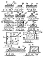
- Fig. 1 shows a bio-mechanical micro-structure 1 of the invention comprising a fused silica substrate 2 in the form of a small plate.
- a fused silica substrate 2 in the form of a small plate.
- two spaced apart and diverging ridge structures 4 in the form of gold fingers each having a width of 6 um and a thickness of 0.4 ⁇ m.
- the spacing between the fingers 4 ranges from 2 to 20 11m and they are formed on the surface 3 by ion-beam etching of gold.
- the silica substrate is optionally coated with a layer of untreated polystyrene having a thickness of about 0.1 pm. The polystyrene coating is applied to the silica surface 3 by evaporation from toluene solution.
- a suspension of nerve cells cultured from chick embryo brain (2-10 x 10 4 cells per ml of aque- oussolution containing Ham's F10 saline with 1% foetal calf serum and additions of transferring, insuling, and nerve growth factor) was then applied to the above-described substrate surface and maintained in contact therewith for 60 minutes at 37°C.
- the excess solution was then drained off and the substrate washed with fresh culture medium. Inspection of the substrate then showed that a number nerve cells 5 had become selectively attached thereto the gold wires and in particular across adjacent pairs of converging gold wires.
- Fig. 2 shows another bio-mechanical microstructure 11 comprising a fused silica substrate 12 with a groove 13 etched in its upper surface 14 by means of argon iron beam etching through a photomicrographically defined photoresist layer.
- each projection 15 has a height of some 0.1 to 0.5 11m and a thickness of about 0.02 to 0.1 pm.
- the projections are desirably formed so as to have a substantially smooth surface so that they penetrate the cell wall readily and the cell wall seals around the projections.
- the projections may be formed by any suitable photolithographic technique. Conveniently the projections may be formed by depositing a thin layer (20-30 nm) of gold or other metal onto a hydrocarbonpolymer pillar formed by polymerisation effects of an electron beam in vacuo making use of traces of organic materials from the vacuum pump oil of the pump used to produce the vacuum (Broers (1)).
- Nerve cells 16 are applied to the substrate surface in a similar manner to that described above and become attached to the groove 13. As shown in the drawing certain projections 15 become phagocytosed by the cell providing a direct mechanical and electrical connection with the cell interior.
- electrical conductor or semi-conductor material tracks or other structures may be provided within the grooves and/or extending outside the grooves a cell-adhesion inhibiting coating may be provided.
- Figs. 3 to 6 show various different arrangements of pluralities of grooves 17 and which can be used to define desired networks of cells 18.
- Fig. 7A to 7/ illustrates schematically the principal stages in a suitable lithographic manufacturing process for the production of another substrate structure further illustrated in Figs. 8 to 10, suitable for use in making direct electrical connections with the interior of a cell. Since the basic lithographic techniques employed in the process are known in the art they will only briefly be described.
- Aluminium metal was evaporated over a glass substrate 19 to form a metal layer 20 of approximately 50 nm thickness. This was then overcoated with a layer of photoresist 21 of similar thickness and exposed through a mask (not shown) defining the pattern of leads to the probes (see below).
- the photoresist 22 was then developed to produce a protective pattern 22 as shown in Fig. 7A which after chemical etching of the unprotected metal 20 and subsequent removal of the resist pattern 22, left a metallic lead pattern 23 as shown in Fig. 78.
- Photoresist was then coated onto the processed substrate surface and exposed to the negative of the first mask to leave, after development resist 24 everywhere but on the metal lead pattern 23 as shown in Fig. 7C.
- Needle-shaped columns 25 of polymerised contamination are then formed at desired spots on the conductor tracks 23 (See Fig. 7D) by focussing an electron beam on said spots.
- the columns 25 of material so formed have a diameter a few times the beam diameter and their height can be made many times the beam diameter (Broers(1)). Any residual hydrocarbons in the vacuum are polymerised by the electron beam.
- the processed substrate is then overcoated with metal so that probe is now metallised 26 and electrically connected to the conductor track pattern 23 (see Fig. 7E).
- the photoresist 24 is then dissolved in a strong solvent thus removing the resist together with the unwanted metal 27 on top of it (see Fig. 7F).
- the resulting processed substrate is then overcoated with polyimide and baked at 350°C to form an insulating layer 28 having a thickness greater than the contained height of the conductor track 23 and metallised probe 26 thereon.
- the polyimide is used in two roles viz to form the ridge to which the cells adhere and to provide an insulator for the probe leads.
- the polyimide layer 28 is then overcoated first with Aluminium 29 and then with photoresist 30 (see Fig.
- the processed substrate is placed in a reactive oxygen plasma and the polyimide not protected by aluminium etched away to leave a polyimide ridge pattern 31 with substantially vertical walls (See Fig. 7H).
- the protective aluminium layer 29 having served its purpose as an oxygen plasma etch mask, it is removed by chemical etching and the processed substrate then returned to the oxygen plasma etcher and more polyimide removed until the probes 26 stand proud of the polyimide ridges 31 (see Fig. 7/).
- the processed substrate is then overcoated with resist and exposed to a further mask defining an electrical screen pattern.
- the metal screen layer 32 will cover the whole specimen except for the cell- supporting polyimide ridges and the contact pads (see Figs. 10 and 11 in particular).
- a selection of glass tube 33 is glued on to the processed substrate to separate the central biological area-containing cell support medium 34 and which will therefore be wet-from the surrounding electrical area.
- the probe leads 35 which are connected to the remote ends of the conductor tracks 23, are electrically isolated from the saline solution cell support medium 34 by a ground plane everywhere except for a few micrometres close to the metallized probe 26. Even here only the tip 36 of the probe will not be insulated and this will be isolated from the medium 34 once it is phagocytosed by a cell 37 attaching to the cell- support polyimide ridge 31 (see Fig. 9).
- Fig. 12 shows schematically a further substrate structure of the invention produced using photolithographic procedures with ion beam milling through suitable masks to form a series of logarithmic spiral grooves 40 in the surface 41 of a glass plate 42.
- the grooves 40 were ten micrometres wide and half a micrometre deep.
- the smallest (innermost end 43) radius of curvature of the spiral was 20 micrometres and the largest (outermost end 44) two hundred and fifty micrometres.
- BHK fibroblast cells 45 were applied on to this substrate in a serum containing culture medium (Eagle's MEM medium with 10 percent tryptose-phosphate broth and ten percent calf serum) and cultured at 37°C for two days.
- serum containing culture medium Eagle's MEM medium with 10 percent tryptose-phosphate broth and ten percent calf serum
- the areas containing the spirals 40 were filmed by time-lapse video recording using phase contrast microscopy and a very low light level video camera, the latter being used in order to minimise any possible adverse effect of light or heat radiation from the microscope lamp.
- the cells were observed locate at the groove within as little as 15 to 30 minutes and take up a spread shape on the groove edges 46 related to the radius of the spiral 40 at that region.
- Cells 47 on the small radius end 43 of the groove 40 did not spread properly and remained immobile.
- Cells 48 settling on wider radii sections elongated to an extent related to the radius of curvature at that region and migrated outwardly along the groove edges 46 to the end of greatest radius 44.
- bio-mechanical structures of the invention particularly those including cell-adhesion enhanced zones, include the separation of cells from other biological material and/or the fractionation of different types of cells on the basis of differences in morphology and cyto-skeleton lability, the cells and/or particular type of cells being preferentially retained by the substrate to which the mixture of interest has been applied whilst other components of the mixture are eluted out of the system.
- the polyimide (or other suitable dielectric) sheath 31 should be dimensioned relative to the dimensions of the conductor tracks 23 and outer metal shielding 32 and the dielectric properties of the sheath so as to obtain a suitable characteristic impedance for this electrical connection.
- the connection should have a characteristic impedance in the range from 25 to 200 ohms. In the specific example shown (note: Figs.
- the conductor track 23 conveniently has a thickness of about 0.2 ⁇ m, the polyimide insulation sheath 31 a thickness in the region of 1 to 2 pm, and the outer conductor shield 32 a thickness of about 0.3 ⁇ m.
Landscapes
- Health & Medical Sciences (AREA)
- Wood Science & Technology (AREA)
- Organic Chemistry (AREA)
- Chemical & Material Sciences (AREA)
- Life Sciences & Earth Sciences (AREA)
- Engineering & Computer Science (AREA)
- Bioinformatics & Cheminformatics (AREA)
- Zoology (AREA)
- Biomedical Technology (AREA)
- Immunology (AREA)
- Microbiology (AREA)
- Biotechnology (AREA)
- Sustainable Development (AREA)
- Biochemistry (AREA)
- General Engineering & Computer Science (AREA)
- General Health & Medical Sciences (AREA)
- Genetics & Genomics (AREA)
- Clinical Laboratory Science (AREA)
- Apparatus Associated With Microorganisms And Enzymes (AREA)
- Immobilizing And Processing Of Enzymes And Microorganisms (AREA)
- Bipolar Transistors (AREA)
- Micro-Organisms Or Cultivation Processes Thereof (AREA)
- Materials For Medical Uses (AREA)
- Laminated Bodies (AREA)
- Investigating Or Analyzing Materials By The Use Of Fluid Adsorption Or Reactions (AREA)
- Junction Field-Effect Transistors (AREA)
Claims (14)
Priority Applications (1)
| Application Number | Priority Date | Filing Date | Title |
|---|---|---|---|
| AT84308230T ATE56749T1 (de) | 1983-11-29 | 1984-11-28 | Mikrostrukturen. |
Applications Claiming Priority (2)
| Application Number | Priority Date | Filing Date | Title |
|---|---|---|---|
| GB8331865 | 1983-11-29 | ||
| GB838331865A GB8331865D0 (en) | 1983-11-29 | 1983-11-29 | Microstructures |
Publications (3)
| Publication Number | Publication Date |
|---|---|
| EP0145406A2 EP0145406A2 (de) | 1985-06-19 |
| EP0145406A3 EP0145406A3 (en) | 1987-08-05 |
| EP0145406B1 true EP0145406B1 (de) | 1990-09-19 |
Family
ID=10552546
Family Applications (1)
| Application Number | Title | Priority Date | Filing Date |
|---|---|---|---|
| EP84308230A Expired - Lifetime EP0145406B1 (de) | 1983-11-29 | 1984-11-28 | Mikrostrukturen |
Country Status (7)
| Country | Link |
|---|---|
| US (1) | US4832759A (de) |
| EP (1) | EP0145406B1 (de) |
| JP (1) | JPH0659208B2 (de) |
| AT (1) | ATE56749T1 (de) |
| DE (1) | DE3483247D1 (de) |
| DK (1) | DK563884A (de) |
| GB (1) | GB8331865D0 (de) |
Families Citing this family (22)
| Publication number | Priority date | Publication date | Assignee | Title |
|---|---|---|---|---|
| GB8526096D0 (en) * | 1985-10-22 | 1985-11-27 | Robinson E | Microcarrier |
| US5079600A (en) * | 1987-03-06 | 1992-01-07 | Schnur Joel M | High resolution patterning on solid substrates |
| US5721131A (en) * | 1987-03-06 | 1998-02-24 | United States Of America As Represented By The Secretary Of The Navy | Surface modification of polymers with self-assembled monolayers that promote adhesion, outgrowth and differentiation of biological cells |
| EP0402718B1 (de) * | 1989-06-03 | 1994-11-02 | Kanegafuchi Kagaku Kogyo Kabushiki Kaisha | Kontrolle der Zellanordnung |
| DE69022778T2 (de) * | 1989-06-09 | 1996-04-18 | Terumo Corp | Zellkultursubstrat, Bioreaktor mit Zellkultursubstrat und therapeutische Vorrichtung vom extrakorporalen Umlauftyp. |
| JPH0541984A (ja) * | 1990-09-07 | 1993-02-23 | Dow Chem Co:The | 攪拌容器における中空繊維においての細胞の増殖 |
| JPH05176753A (ja) * | 1991-12-26 | 1993-07-20 | Nec Corp | 細胞培養用基板とその作製方法 |
| US5240024A (en) * | 1992-03-31 | 1993-08-31 | Moore Epitaxial, Inc. | Automated process gas supply system for evacuating a process line |
| US20020133232A1 (en) * | 1993-11-02 | 2002-09-19 | Ricci John L. | Microstructured dual sided membrane for tissue growth and regeneration |
| GB9403135D0 (en) * | 1994-02-18 | 1994-04-06 | Univ Glasgow | Wound healing device |
| JP3704411B2 (ja) * | 1996-12-26 | 2005-10-12 | 富士通株式会社 | 基板処理方法及び処理装置 |
| US6251595B1 (en) | 1998-06-18 | 2001-06-26 | Agilent Technologies, Inc. | Methods and devices for carrying out chemical reactions |
| EP1013756A1 (de) * | 1998-12-21 | 2000-06-28 | Corning Incorporated | Vorrichtung Zur Vermehrung von zellen die die Zellenverbindungdurch das Wachstumsprozes ermöglicht und Verfahren zur ihre Herstellung |
| US6193647B1 (en) | 1999-04-08 | 2001-02-27 | The Board Of Trustees Of The University Of Illinois | Microfluidic embryo and/or oocyte handling device and method |
| IL148096A0 (en) * | 1999-08-10 | 2002-09-12 | Acorda Therapeutics Inc | Bioartificial device for propagation of tissue, preparation and uses thereof |
| GB0114399D0 (en) * | 2001-06-13 | 2001-08-08 | Univ Liverpool | Substrates, biomaterials and methods |
| DE10142637B4 (de) * | 2001-08-31 | 2009-07-09 | Disetronic Licensing Ag | Transkutanes Implantat mit Oberflächenstruktur sowie Verfahren zur Herstellung eines solchen Implantats |
| GB2381535A (en) * | 2001-10-30 | 2003-05-07 | Qinetiq Ltd | Device for forming a cellular network |
| US20050203601A1 (en) * | 2003-02-14 | 2005-09-15 | Daniel Palanker | Neural stimulation array providing proximity of electrodes to cells via cellular migration |
| US20050244898A1 (en) * | 2003-11-19 | 2005-11-03 | Cohen Robert E | Large-area two-dimensional non-adhesive cell arrays for sensing and cell-sorting applications |
| US20050228491A1 (en) * | 2004-04-12 | 2005-10-13 | Snyder Alan J | Anti-adhesive surface treatments |
| US9157550B2 (en) * | 2009-01-05 | 2015-10-13 | The Board Of Trustees Of The University Of Illinois | Microfluidic systems and methods |
Family Cites Families (2)
| Publication number | Priority date | Publication date | Assignee | Title |
|---|---|---|---|---|
| GB1509826A (en) * | 1976-06-25 | 1978-05-04 | Merck & Co Inc | Growth surfaces for tissue cell cultures |
| CA1201400A (en) * | 1982-04-16 | 1986-03-04 | Joel L. Williams | Chemically specific surfaces for influencing cell activity during culture |
-
1983
- 1983-11-29 GB GB838331865A patent/GB8331865D0/en active Pending
-
1984
- 1984-11-28 DK DK563884A patent/DK563884A/da not_active Application Discontinuation
- 1984-11-28 DE DE8484308230T patent/DE3483247D1/de not_active Expired - Lifetime
- 1984-11-28 AT AT84308230T patent/ATE56749T1/de not_active IP Right Cessation
- 1984-11-28 EP EP84308230A patent/EP0145406B1/de not_active Expired - Lifetime
- 1984-11-29 JP JP59250643A patent/JPH0659208B2/ja not_active Expired - Lifetime
-
1988
- 1988-07-19 US US07/220,413 patent/US4832759A/en not_active Expired - Lifetime
Also Published As
| Publication number | Publication date |
|---|---|
| ATE56749T1 (de) | 1990-10-15 |
| DE3483247D1 (de) | 1990-10-25 |
| DK563884D0 (da) | 1984-11-28 |
| EP0145406A3 (en) | 1987-08-05 |
| JPH0659208B2 (ja) | 1994-08-10 |
| EP0145406A2 (de) | 1985-06-19 |
| US4832759A (en) | 1989-05-23 |
| GB8331865D0 (en) | 1984-01-04 |
| JPS60203191A (ja) | 1985-10-14 |
| DK563884A (da) | 1985-05-30 |
Similar Documents
| Publication | Publication Date | Title |
|---|---|---|
| EP0145406B1 (de) | Mikrostrukturen | |
| Gross et al. | Transparent indium-tin oxide electrode patterns for extracellular, multisite recording in neuronal cultures | |
| US4231660A (en) | Microscope slide with electrode arrangement for cell study, and method for its construction | |
| CA1066209A (en) | Microdevice substrate and method for making micropattern devices | |
| US4767418A (en) | Luminal surface fabrication for cardiovascular prostheses | |
| EP0213902B1 (de) | Herstellung von Mikrosieben sowie nach diesem Verfahren hergestellte Mikrosiebe | |
| US6834200B2 (en) | Ceramic based multi-site electrode arrays and methods for their production | |
| US4338164A (en) | Method for producing planar surfaces having very fine peaks in the micron range | |
| Smirnova et al. | Microtubule converging centers and reorganization of the interphase cytoskeleton and the mitotic spindle in higher plant Haemanthus | |
| TW201123297A (en) | Apparatus and methods for supporting workpieces during plasma processing | |
| JPS60100662A (ja) | 炭素を含む層の製造方法 | |
| US4507180A (en) | Method of electrodepositing a homogeneously thick metal layer, metal layer thus obtained and the use of the metal layer thus obtained, device for carrying out the method and resulting matrix | |
| US4302316A (en) | Non-contacting technique for electroplating X-ray lithography | |
| US6077405A (en) | Method and apparatus for making electrical contact to a substrate during electroplating | |
| WO1998046810A1 (en) | Bipolar electrochemical connection of materials | |
| Hottenhuis et al. | Scanning tunneling microscopy in an electrochemical system | |
| Shandhi et al. | Reusable high aspect ratio 3-D nickel shadow mask | |
| CN109867260A (zh) | 在非导电衬底上进行电子束/离子束聚焦刻蚀及显微成像的方法 | |
| US4361641A (en) | Electrolytic surface modulation | |
| CN1083870A (zh) | 单向场发生器 | |
| JPH04278080A (ja) | 神経回路の作製方法 | |
| EP0396583A1 (de) | Niederschlag von stoffen in einem gewünschten muster auf unterlagen | |
| Keast | A chemical thinning technique for the simultaneous preparation of foils for transmission electron microscopy: application to yttrium aluminium garnet | |
| JP2000297396A (ja) | 金属微細パタン形成法 | |
| JPH037756B2 (de) |
Legal Events
| Date | Code | Title | Description |
|---|---|---|---|
| PUAI | Public reference made under article 153(3) epc to a published international application that has entered the european phase |
Free format text: ORIGINAL CODE: 0009012 |
|
| AK | Designated contracting states |
Designated state(s): AT BE CH DE FR GB IT LI LU NL SE |
|
| PUAL | Search report despatched |
Free format text: ORIGINAL CODE: 0009013 |
|
| AK | Designated contracting states |
Kind code of ref document: A3 Designated state(s): AT BE CH DE FR GB IT LI LU NL SE |
|
| 17P | Request for examination filed |
Effective date: 19880204 |
|
| 17Q | First examination report despatched |
Effective date: 19890725 |
|
| GRAA | (expected) grant |
Free format text: ORIGINAL CODE: 0009210 |
|
| AK | Designated contracting states |
Kind code of ref document: B1 Designated state(s): AT BE CH DE FR GB IT LI LU NL SE |
|
| PG25 | Lapsed in a contracting state [announced via postgrant information from national office to epo] |
Ref country code: SE Effective date: 19900919 Ref country code: NL Effective date: 19900919 Ref country code: LI Effective date: 19900919 Ref country code: IT Free format text: LAPSE BECAUSE OF FAILURE TO SUBMIT A TRANSLATION OF THE DESCRIPTION OR TO PAY THE FEE WITHIN THE PRESCRIBED TIME-LIMIT;WARNING: LAPSES OF ITALIAN PATENTS WITH EFFECTIVE DATE BEFORE 2007 MAY HAVE OCCURRED AT ANY TIME BEFORE 2007. THE CORRECT EFFECTIVE DATE MAY BE DIFFERENT FROM THE ONE RECORDED. Effective date: 19900919 Ref country code: FR Effective date: 19900919 Ref country code: CH Effective date: 19900919 Ref country code: BE Effective date: 19900919 Ref country code: AT Effective date: 19900919 |
|
| REF | Corresponds to: |
Ref document number: 56749 Country of ref document: AT Date of ref document: 19901015 Kind code of ref document: T |
|
| REF | Corresponds to: |
Ref document number: 3483247 Country of ref document: DE Date of ref document: 19901025 |
|
| PG25 | Lapsed in a contracting state [announced via postgrant information from national office to epo] |
Ref country code: LU Free format text: LAPSE BECAUSE OF NON-PAYMENT OF DUE FEES Effective date: 19901130 |
|
| REG | Reference to a national code |
Ref country code: CH Ref legal event code: PL |
|
| EN | Fr: translation not filed | ||
| NLV1 | Nl: lapsed or annulled due to failure to fulfill the requirements of art. 29p and 29m of the patents act | ||
| PLBE | No opposition filed within time limit |
Free format text: ORIGINAL CODE: 0009261 |
|
| STAA | Information on the status of an ep patent application or granted ep patent |
Free format text: STATUS: NO OPPOSITION FILED WITHIN TIME LIMIT |
|
| 26N | No opposition filed | ||
| REG | Reference to a national code |
Ref country code: GB Ref legal event code: IF02 |
|
| PGFP | Annual fee paid to national office [announced via postgrant information from national office to epo] |
Ref country code: GB Payment date: 20020404 Year of fee payment: 18 |
|
| PGFP | Annual fee paid to national office [announced via postgrant information from national office to epo] |
Ref country code: DE Payment date: 20020410 Year of fee payment: 18 |
|
| PG25 | Lapsed in a contracting state [announced via postgrant information from national office to epo] |
Ref country code: GB Free format text: LAPSE BECAUSE OF NON-PAYMENT OF DUE FEES Effective date: 20021128 |
|
| PG25 | Lapsed in a contracting state [announced via postgrant information from national office to epo] |
Ref country code: DE Free format text: LAPSE BECAUSE OF NON-PAYMENT OF DUE FEES Effective date: 20030603 |
|
| GBPC | Gb: european patent ceased through non-payment of renewal fee |