EP0148727A1 - Gestrickaufwickelvorrichtung für eine Rundstrickmaschine - Google Patents
Gestrickaufwickelvorrichtung für eine Rundstrickmaschine Download PDFInfo
- Publication number
- EP0148727A1 EP0148727A1 EP84810596A EP84810596A EP0148727A1 EP 0148727 A1 EP0148727 A1 EP 0148727A1 EP 84810596 A EP84810596 A EP 84810596A EP 84810596 A EP84810596 A EP 84810596A EP 0148727 A1 EP0148727 A1 EP 0148727A1
- Authority
- EP
- European Patent Office
- Prior art keywords
- fabric
- roller
- axis
- stirrup
- pair
- Prior art date
- Legal status (The legal status is an assumption and is not a legal conclusion. Google has not performed a legal analysis and makes no representation as to the accuracy of the status listed.)
- Withdrawn
Links
- 239000004744 fabric Substances 0.000 title claims abstract description 37
- 238000009940 knitting Methods 0.000 title claims abstract description 24
- 238000004804 winding Methods 0.000 title claims abstract description 24
- 238000011144 upstream manufacturing Methods 0.000 claims abstract description 5
- 238000010586 diagram Methods 0.000 description 2
- 238000013459 approach Methods 0.000 description 1
- 238000000605 extraction Methods 0.000 description 1
- 238000005259 measurement Methods 0.000 description 1
Images

Classifications
-
- D—TEXTILES; PAPER
- D04—BRAIDING; LACE-MAKING; KNITTING; TRIMMINGS; NON-WOVEN FABRICS
- D04B—KNITTING
- D04B15/00—Details of, or auxiliary devices incorporated in, weft knitting machines, restricted to machines of this kind
- D04B15/88—Take-up or draw-off devices for knitting products
Definitions
- the subject of the present invention is a mechanism for winding a fabric for a circular knitting machine comprising at least two pinch rollers for the fabric arranged in a horizontal plane and between which the fabric passes after having surrounded a portion of the first roller and the leaves after having surrounded a portion of the second roller, a winding bar and means for driving these rollers and this bar.
- the pinch rollers of the fabric have the role of exerting a determined traction on the knitting and thus ensuring the regularity of the stitches.
- the winding roller is used to collect the knitted fabric with a certain tension which ensures an even width of the wound product. It has already been proposed to pass the knitting alternately below and above two or even three pinch rollers so that the friction generated between the rollers and the fabric reduces the passage of tension between the strands situated above and below. these rollers.
- any slippage of the knitted fabric is not excluded through the pinch rollers, on the other hand, the diameter of the winding roller varies constantly, which implies a variable drive speed of the winding roller so that the winding tension is constant.
- the patent CH-A-501 084 relates to a magnetic braking device comprising a magnet, a lever actuating this magnet and the position of which depends on the diameter of the roll of fabric. As this diameter increases, the lever approaches the magnet of a drum integral with the axis of the fabric roll and brakes it.
- Patent CH-A-539,156 relates to a device in which the fabric extraction roller is kinematically integral with the needle bed and is therefore driven positively at a speed proportional to that of the needle bed. Such a solution does not solve the problem of the possible sliding of the fabric between the pinch rollers or that of the drive of the winding roller.
- the object of the present invention is precisely to solve this problem.
- the subject of this invention is a mechanism for winding a fabric for a circular knitting machine according to claim 1.
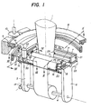
- Fig. 1 only illustrates the knitting winding mechanism produced by the circular knitting loom which has not been shown.
- This knitting is in the form of a tube 1 which is flattened between two pinch rollers 2 and 3 before winding the fabric on a winding bar 4 rotatably mounted around its longitudinal axis between two arms 5 and 6 of a stirrup 7 secured to a ring gear 8 mounted relatively in a circular slide re 9 secured to the frame of the loom and engaged with a drive pinion 10 kinematically connected to the motor mechanism (not shown) intended to rotate the needle bed.
- the winding bar 4 carries a pinion 12 (fig. 3) at one end engaged with a worm 13 of a direct drive motor 14 (fig. 1).
- the electric power is supplied by a double circular conductive track 11 against which two sensors 11a rubbed against the caliper 7 rub.
- the pinch rollers 2 and 3 are rotatably mounted between two arms 15 and 16 of a tilting stirrup 17.
- This stirrup 17 is articulated around an axis 18 passing through the generatrix of the roll 2 (fig. 2) at the location where the knitting 1 leaves this roller 2, and secured to two arms 19 and 20 of a second tilting stirrup 21 articulated around an axis 22 passing through the generatrix of the pinch roller 3 at the place where the knitting 1 enters contact with this roller, and secured to the arms 5 and 6 of the stirrup 7 secured to the ring gear 8.
- Two bars 35 and 36 are fixed between the arms 19 and 20 of the stirrup 21 and serve to keep constant the direction of the force exerted by the strand of fabric extending from the roller 2 to the bar of winding 4 whatever the diameter of the roll of fabric wound on this bar 4.
- the pinch roller 2 is integral with one end (FIG. 4) of a pinion 23 engaged with an endless screw 24 of the shaft of a DC drive motor 25, and at its other end ( Fig. 1) of a toothed gear 26 engaged with a toothed gear 27 secured to the pinch roller shaft 3.
- a first force sensor 28 (fig. 2) constituted by a strain gauge is disposed between the stirrup 7 secured to the toothed ring 8 and the tilting stirrup 21 articulated around the axis 22 and a second force sensor 29 is arranged between the tilting stirrup 21 and the tilting stirrup 17 articulated around the axis 18.
- Fig. 5 illustrates a block diagram of the electronic circuit intended to control the speed of the motor 14 or of the motor 25 to the force picked up by the force sensors 28 respectively 29. Since the control circuit is identical in both cases, only one of these circuits is shown and described.
- the force sensor 28 is connected by a preamplifier 30 to one of the inputs of a differential amplifier 31, the other input of which is connected to a reference potentiometer 32 which serves to display a voltage characteristic of the desired force on the sensor force 28.
- the output of the differential amplifier 31 is connected to a regulator 33 itself connected to a power amplifier 34 intended to supply the motor 14.
- the principle of adjustment of the mechanism for winding the knitted fabric consists in controlling the speed of the motor 14 to the tension of the knitting portion 1 extending from the pinch roller 2 to the knitting roller formed on the winding bar 4 and to control the speed of the motor 25 to the tension of the knitting portion extending between the pinch roller 3 and the needles integral with the needle bed (not shown).
- the pivot axis 18 of the tilting stirrup 17 being coincident with the generatrix of the pinch roller 2 at the place where the knitted fabric 1 leaves this roller 2 and the knitted fabric passes successively under the roller 3 between the rollers 2 and 3 and on the roller 2, the torque exerted on the stirrup 17 around the hinge axis 18 is directly proportional to the tension of the portion of fabric extending between the roller 3 and the needles of the fcnture (not shown).
- the tension of the knitting strand located between the roller 2 and the winding bar 4 does not enter the line of the joint because the lever arm of this force, the point of application of which coincides with the axis 18, is no.
- the knitting path between the pinch rollers 2 and 3 prevents to some extent the tension in the knitting strand extending between the roller 2 and the bar 4 from being transmitted to the other strand of knitting located upstream of the roll 3.
- the force measured by the force sensor 29 is very characteristic of the moment corresponding to the product of the force exerted by the knitting strand 1 extending between the roller 3 and the needles of the needle bed (not shown) tangentially to the roller 3, by the lever arm for applying this force relative to the tilting axis of the stirrup 17.
- the voltage emitted by the force sensor 29 is proportional to this mo ment so that the differential amplifier 31 and the regulator 33 regulate the power supply to the motor 25 according to the difference between the voltage emitted by the sensor 29 and that displayed by the setpoint potentiometer 32 and corresponding to the voltage desired mechanics in the strand of knitted fabric 1 extending upstream of the roller 3.
- the torque exerted on the stirrup 21 is proportional to the only force of the knitting strand extending between the roller 2 and the winding bar 4.
- the force proportional to this torque measured by the sensor 28 serves to adjust the tension motor supply 14.
- this supply voltage is adjusted by an electronic circuit identical to that of the motor 14 as a function of the reference voltage displayed on the reference potentiometer 32 and corresponding to the desired mechanical voltage in the strand of the knitting 1 extending downstream of the roll 2.
Landscapes
- Engineering & Computer Science (AREA)
- Textile Engineering (AREA)
- Knitting Machines (AREA)
Applications Claiming Priority (2)
| Application Number | Priority Date | Filing Date | Title |
|---|---|---|---|
| CH6504/83 | 1983-12-06 | ||
| CH650483 | 1983-12-06 |
Publications (1)
| Publication Number | Publication Date |
|---|---|
| EP0148727A1 true EP0148727A1 (de) | 1985-07-17 |
Family
ID=4310658
Family Applications (2)
| Application Number | Title | Priority Date | Filing Date |
|---|---|---|---|
| EP84810596A Withdrawn EP0148727A1 (de) | 1983-12-06 | 1984-12-05 | Gestrickaufwickelvorrichtung für eine Rundstrickmaschine |
| EP19850900034 Withdrawn EP0163703A1 (de) | 1983-12-06 | 1984-12-05 | Gestrickaufwickelvorrichtung für eine rundstrickmaschine |
Family Applications After (1)
| Application Number | Title | Priority Date | Filing Date |
|---|---|---|---|
| EP19850900034 Withdrawn EP0163703A1 (de) | 1983-12-06 | 1984-12-05 | Gestrickaufwickelvorrichtung für eine rundstrickmaschine |
Country Status (2)
| Country | Link |
|---|---|
| EP (2) | EP0148727A1 (de) |
| WO (1) | WO1985002633A1 (de) |
Cited By (4)
| Publication number | Priority date | Publication date | Assignee | Title |
|---|---|---|---|---|
| EP0591988A1 (de) * | 1992-10-09 | 1994-04-13 | Precision Fukuhara Works, Ltd | Stoffwickelvorrichtung für Rundstrickmaschine |
| EP0622486A1 (de) * | 1992-12-07 | 1994-11-02 | Precision Fukuhara Works, Ltd | Waren-Aufwickelvorrichtung für Rundstrickmaschinen |
| GB2316955A (en) * | 1996-09-05 | 1998-03-11 | Pai Lung Machinery Mill Co Ltd | A fabric rolling-up device with automatic torque increase circuit. |
| DE19833509B4 (de) * | 1997-07-25 | 2008-08-28 | Santoni S.P.A. | Rundstrickmaschine mit einer Zugvorrichtung für Strickware |
Families Citing this family (2)
| Publication number | Priority date | Publication date | Assignee | Title |
|---|---|---|---|---|
| US4879886A (en) * | 1987-05-01 | 1989-11-14 | Gunze Limited | Circular knitting machine |
| CN1191400C (zh) | 1999-05-19 | 2005-03-02 | Sipra专利发展合作股份有限公司 | 用于引导在针织机上做出的针织品的辊子和具有该辊子的装置 |
Citations (4)
| Publication number | Priority date | Publication date | Assignee | Title |
|---|---|---|---|---|
| FR1267726A (fr) * | 1960-09-20 | 1961-07-21 | Maschf Augsburg Nuernberg Ag | Dispositif de réglage de la tension d'une bande de papier, en particulier entre les mécanismes d'impression des machines rotatives au moyen d'un ou de plusieurs rouleaux d'entraînement entraînés avec variation continue de la vitesse |
| GB1134169A (en) * | 1966-03-22 | 1968-11-20 | Gayley Wycombe Corp | Improvement in take-up apparatus for textile fabric webs |
| US3842627A (en) * | 1969-07-28 | 1974-10-22 | Travis Mills Corp | Means for rolling up tubular fabric produced by a circular knitting machine |
| DE2555948A1 (de) * | 1975-12-12 | 1977-06-16 | Schlafhorst & Co W | Verfahren und vorrichtung zur regelung der spannkraft eines bahnfoermig zugefuehrten gutes |
-
1984
- 1984-12-05 EP EP84810596A patent/EP0148727A1/de not_active Withdrawn
- 1984-12-05 EP EP19850900034 patent/EP0163703A1/de not_active Withdrawn
- 1984-12-05 WO PCT/CH1984/000190 patent/WO1985002633A1/fr not_active Ceased
Patent Citations (4)
| Publication number | Priority date | Publication date | Assignee | Title |
|---|---|---|---|---|
| FR1267726A (fr) * | 1960-09-20 | 1961-07-21 | Maschf Augsburg Nuernberg Ag | Dispositif de réglage de la tension d'une bande de papier, en particulier entre les mécanismes d'impression des machines rotatives au moyen d'un ou de plusieurs rouleaux d'entraînement entraînés avec variation continue de la vitesse |
| GB1134169A (en) * | 1966-03-22 | 1968-11-20 | Gayley Wycombe Corp | Improvement in take-up apparatus for textile fabric webs |
| US3842627A (en) * | 1969-07-28 | 1974-10-22 | Travis Mills Corp | Means for rolling up tubular fabric produced by a circular knitting machine |
| DE2555948A1 (de) * | 1975-12-12 | 1977-06-16 | Schlafhorst & Co W | Verfahren und vorrichtung zur regelung der spannkraft eines bahnfoermig zugefuehrten gutes |
Cited By (6)
| Publication number | Priority date | Publication date | Assignee | Title |
|---|---|---|---|---|
| EP0591988A1 (de) * | 1992-10-09 | 1994-04-13 | Precision Fukuhara Works, Ltd | Stoffwickelvorrichtung für Rundstrickmaschine |
| US5381676A (en) * | 1992-10-09 | 1995-01-17 | Precision Fukuhara Works, Ltd. | Fabric take-up mechanism for circular knitting machines |
| EP0622486A1 (de) * | 1992-12-07 | 1994-11-02 | Precision Fukuhara Works, Ltd | Waren-Aufwickelvorrichtung für Rundstrickmaschinen |
| GB2316955A (en) * | 1996-09-05 | 1998-03-11 | Pai Lung Machinery Mill Co Ltd | A fabric rolling-up device with automatic torque increase circuit. |
| GB2316955B (en) * | 1996-09-05 | 2000-08-02 | Pai Lung Machinery Mill Co Ltd | Fabric rolling-up device and control circuit assembly |
| DE19833509B4 (de) * | 1997-07-25 | 2008-08-28 | Santoni S.P.A. | Rundstrickmaschine mit einer Zugvorrichtung für Strickware |
Also Published As
| Publication number | Publication date |
|---|---|
| EP0163703A1 (de) | 1985-12-11 |
| WO1985002633A1 (fr) | 1985-06-20 |
Similar Documents
| Publication | Publication Date | Title |
|---|---|---|
| EP0046427B1 (de) | Bindeeinrichtung für Rundballenpressen | |
| US5133197A (en) | Apparatus for drawing knitted fabrics | |
| EP0148727A1 (de) | Gestrickaufwickelvorrichtung für eine Rundstrickmaschine | |
| EP0305230A1 (de) | Periodische Papierbahnzufuhr einer Maschine, insbesondere für eine blattabschneidende Presse | |
| EP0357670A1 (de) | Jigger. | |
| BE1001096A3 (fr) | Dispositif pour enrouler des nappes de matiere sur des rouleaux de reserve. | |
| US5317913A (en) | Apparatus for determining the sag of a running web of material transversely to its longitudinal direction | |
| FR2639366A1 (fr) | Machine a tisser equipee d'un regulateur de tension pour rouleau de devidage ou d'appel d'une nappe textile | |
| FR2844528A1 (fr) | Appareil a poulies reglables pour banc d 'etirage | |
| CA2512740A1 (fr) | Procedes de preparation de derives de la dhea | |
| BE568019A (de) | ||
| CH302598A (fr) | Procédé de mesure continue d'une grandeur variable et dispositif pour sa mise en oeuvre. | |
| FR2844527A1 (fr) | Appareil de reglage pour banc d'etirage | |
| JPH087058B2 (ja) | 長尺体の計尺装置 | |
| FR2518590A1 (fr) | Dispositif pour la regulation de la tension des fils de chaine sur une machine a tisser | |
| BE558444A (de) | ||
| FR2514736A1 (fr) | Rouleau pour matiere textile avec un dispositif de freinage | |
| BE532587A (de) | ||
| CH450003A (fr) | Appareil automatique pour mesurer et enregistrer le degré de torsion d'un fil | |
| CH296449A (fr) | Treuil pour l'acheminement d'un câble sous tension mécanique. | |
| FR2855190A1 (fr) | Dispositif de reglage et de controle de la stabilite de l'equilibre de tension d'un fil synthetique | |
| BE489204A (de) | ||
| FR2681617A1 (fr) | Enrouleur-derouleur de materiau plan, notamment textile, a double-sens et a tension controlee. | |
| EP0526332A1 (de) | Vorrichtung zum Schneiden eines Seifenstücks | |
| BE518437A (de) |
Legal Events
| Date | Code | Title | Description |
|---|---|---|---|
| PUAI | Public reference made under article 153(3) epc to a published international application that has entered the european phase |
Free format text: ORIGINAL CODE: 0009012 |
|
| AK | Designated contracting states |
Designated state(s): IT |
|
| STAA | Information on the status of an ep patent application or granted ep patent |
Free format text: STATUS: THE APPLICATION HAS BEEN WITHDRAWN |
|
| 18W | Application withdrawn |
Withdrawal date: 19851210 |
|
| RIN1 | Information on inventor provided before grant (corrected) |
Inventor name: COTTENCEAU, REMY Inventor name: ZURCHER, ERWIN Inventor name: FARKAS, RUDOLF |