EP0150518A1 - Flowdrill, particularly adapted to be used in a hand drilling machine - Google Patents
Flowdrill, particularly adapted to be used in a hand drilling machine Download PDFInfo
- Publication number
- EP0150518A1 EP0150518A1 EP84200120A EP84200120A EP0150518A1 EP 0150518 A1 EP0150518 A1 EP 0150518A1 EP 84200120 A EP84200120 A EP 84200120A EP 84200120 A EP84200120 A EP 84200120A EP 0150518 A1 EP0150518 A1 EP 0150518A1
- Authority
- EP
- European Patent Office
- Prior art keywords
- flowdrill
- drill
- cutting edges
- drilling machine
- shaft
- Prior art date
- Legal status (The legal status is an assumption and is not a legal conclusion. Google has not performed a legal analysis and makes no representation as to the accuracy of the status listed.)
- Granted
Links
- 238000005553 drilling Methods 0.000 title abstract description 7
- 230000004323 axial length Effects 0.000 claims description 3
Images
Classifications
-
- B—PERFORMING OPERATIONS; TRANSPORTING
- B21—MECHANICAL METAL-WORKING WITHOUT ESSENTIALLY REMOVING MATERIAL; PUNCHING METAL
- B21J—FORGING; HAMMERING; PRESSING METAL; RIVETING; FORGE FURNACES
- B21J5/00—Methods for forging, hammering, or pressing; Special equipment or accessories therefor
- B21J5/06—Methods for forging, hammering, or pressing; Special equipment or accessories therefor for performing particular operations
- B21J5/063—Friction heat forging
- B21J5/066—Flow drilling
-
- B—PERFORMING OPERATIONS; TRANSPORTING
- B23—MACHINE TOOLS; METAL-WORKING NOT OTHERWISE PROVIDED FOR
- B23B—TURNING; BORING
- B23B51/00—Tools for drilling machines
- B23B51/08—Drills combined with tool parts or tools for performing additional working
Definitions
- the invention relates to a flowdrill, having a shaft with a substantially smooth, tapering effective end.
- Such flowdrills are known, e.g. from the French patent 1.189.384, the Dutch patent 160.499 and the European patent 57039. They operate satisfactoraly in larger stationary drilling machines, in which they may be brought into engagement with a workpiece by a sufficient axial force, so that so much heat is generated due to the friction with the usually sheetlike workpiece, that a beginning of the hole to be drilled is formed.
- the drill according to the invention likewise may be used with advantage in a stationary drilling machine, in which the obtainable feed force is not sufficient to quickly produce a hole by means of a conventional flowdrill.
- the cutting edges are formed in the shaft tip by means of recesses having sharp edges, which are provided in the tip surface.
- the axial length of the shaft portion having the cutting edges will have a length equal to about 1/3 of the hole diameter to be provided. For it is, if this length is too small, there is no sufficient space for leading away the chip which is formed during cutting, whereas if the length of the cutting edge or edges is too large, too much material is cut away, so that the sleeve, which is formed, as will be further described below, becomes too thin.
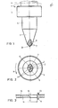
- the flowdrill 1 as shown in figure 1 has a so called center tip 2 which merges with a tapering drill portion 3 which in turn merges with a cylindrical shaft portion 4. Above said cylindrical shaft portion a collar 5 is provided which is followed by a shaft portion 6, which is adapted to clamp the drill in the drilling head of a drilling machine.
- Figure 3 shows a cross-section of a piece of sheet material 10 in which a hole, having a diameter 11, may be provided by using the drill, the hole diameter corresponding to the diameter of the drill shaft portion 4.
- a hole having a diameter 11
- the drill starts operating first the portion 12, to the left in figure 3, is cut away by the cutting edges 7, whereafter the smooth flowdrill portion 3 enters in action and finally the hole is obtained, as shown to the right in figure 3, having an upset collar 13 at the upper end and an extruded sleeve shaped projection 14 at the lower side of the hole.
- This upset material at both sides of the sheet provides additional material for the provision of screw thread whereby the sheet may be secured to other parts by means of bolts or screws.
- the axial length of the portion having the cutting edges 7 is substantially equal to 1/3 of the diameter of the holes to be made and therefore of the diameter of the shaft portion 4.
Landscapes
- Engineering & Computer Science (AREA)
- Mechanical Engineering (AREA)
- Drilling Tools (AREA)
- Polishing Bodies And Polishing Tools (AREA)
- Perforating, Stamping-Out Or Severing By Means Other Than Cutting (AREA)
Abstract
Description
- The invention relates to a flowdrill, having a shaft with a substantially smooth, tapering effective end.
- Such flowdrills are known, e.g. from the French patent 1.189.384, the Dutch patent 160.499 and the European patent 57039. They operate satisfactoraly in larger stationary drilling machines, in which they may be brought into engagement with a workpiece by a sufficient axial force, so that so much heat is generated due to the friction with the usually sheetlike workpiece, that a beginning of the hole to be drilled is formed.
- The use of a flowdrill in a hand held drilling machine is practically impossible since then the user would have to produce himself the axial feed force.
- It has now appeared through experiments that this disadvantage may be overcome if for this purpose a special flowdrill is used, namely a flowdrill in which one or more cutting edges have been provided on the effective shaft surface, adjacent to the tip of the tapered portion.
- Thereby a beginning of the hole is generated by the cutting edges and this quickly and without a strong axial feed force, Thereafter the drill moves downwardly into the hole to such a distance that the cutting edges have passed the hole so that the drill furthermore operates like a conventional flowdrill.
- The drill according to the invention likewise may be used with advantage in a stationary drilling machine, in which the obtainable feed force is not sufficient to quickly produce a hole by means of a conventional flowdrill.
- Preferably the cutting edges are formed in the shaft tip by means of recesses having sharp edges, which are provided in the tip surface.
- In most cases with the drill according to the invention the axial length of the shaft portion having the cutting edges will have a length equal to about 1/3 of the hole diameter to be provided. For it is, if this length is too small, there is no sufficient space for leading away the chip which is formed during cutting, whereas if the length of the cutting edge or edges is too large, too much material is cut away, so that the sleeve, which is formed, as will be further described below, becomes too thin.
- The invention will be further explained below with reference to the drawing, showing as an example an embodiment of the flowdrill according to the invention.
-
- Figure 1 shows a side view of the flowdrill.
- Figure 2 is a view from below of said drill.
- Figure 3 shows a cross-section of a hole, made by the flowdrill according to figures 1 and 2 , namely the left part of the figure after
- the passage of the drilltip and the right part of the figure after the passage of the complete drill.
- The flowdrill 1 as shown in figure 1 has a so called
center tip 2 which merges with a taperingdrill portion 3 which in turn merges with acylindrical shaft portion 4. Above said cylindrical shaft portion acollar 5 is provided which is followed by ashaft portion 6, which is adapted to clamp the drill in the drilling head of a drilling machine. - It appears from figure 1 in combination with figure 2, that adjacent the lower end of the drill,cutting
edges 7, in this case two cutting edges, have been formed. In the embodiment shown, said cutting edges have been formed by providing tworecesses 8 in the relative drill portion, e.g. by grinding, whereby thesharp cutting edges 8 are generated. Saidcutting edges 7 are effective if the drill rotates according to thearrows 9 as shown in the drawing. - Figure 3 shows a cross-section of a piece of
sheet material 10 in which a hole, having adiameter 11, may be provided by using the drill, the hole diameter corresponding to the diameter of thedrill shaft portion 4. When the drill starts operating first theportion 12, to the left in figure 3, is cut away by thecutting edges 7, whereafter thesmooth flowdrill portion 3 enters in action and finally the hole is obtained, as shown to the right in figure 3, having anupset collar 13 at the upper end and an extruded sleeve shapedprojection 14 at the lower side of the hole. This upset material at both sides of the sheet provides additional material for the provision of screw thread whereby the sheet may be secured to other parts by means of bolts or screws. - It will be clear that the cutting edges in the lower shaft portion of the drill may be formed in a manner which differs from that which has been described above.
- As said, preferably the axial length of the portion having the
cutting edges 7 is substantially equal to 1/3 of the diameter of the holes to be made and therefore of the diameter of theshaft portion 4.
Claims (3)
Priority Applications (3)
| Application Number | Priority Date | Filing Date | Title |
|---|---|---|---|
| EP84200120A EP0150518B1 (en) | 1984-01-30 | 1984-01-30 | Flowdrill, particularly adapted to be used in a hand drilling machine |
| DE8484200120T DE3470856D1 (en) | 1984-01-30 | 1984-01-30 | Flowdrill, particularly adapted to be used in a hand drilling machine |
| AT84200120T ATE33954T1 (en) | 1984-01-30 | 1984-01-30 | DRILLING TOOL, PARTICULARLY FOR USE IN A HAND DRILLING MACHINE. |
Applications Claiming Priority (1)
| Application Number | Priority Date | Filing Date | Title |
|---|---|---|---|
| EP84200120A EP0150518B1 (en) | 1984-01-30 | 1984-01-30 | Flowdrill, particularly adapted to be used in a hand drilling machine |
Publications (2)
| Publication Number | Publication Date |
|---|---|
| EP0150518A1 true EP0150518A1 (en) | 1985-08-07 |
| EP0150518B1 EP0150518B1 (en) | 1988-05-04 |
Family
ID=8192410
Family Applications (1)
| Application Number | Title | Priority Date | Filing Date |
|---|---|---|---|
| EP84200120A Expired EP0150518B1 (en) | 1984-01-30 | 1984-01-30 | Flowdrill, particularly adapted to be used in a hand drilling machine |
Country Status (3)
| Country | Link |
|---|---|
| EP (1) | EP0150518B1 (en) |
| AT (1) | ATE33954T1 (en) |
| DE (1) | DE3470856D1 (en) |
Cited By (7)
| Publication number | Priority date | Publication date | Assignee | Title |
|---|---|---|---|---|
| GB2181375A (en) * | 1985-10-11 | 1987-04-23 | Anthony George Gigg | Drilling element |
| EP0913493A1 (en) * | 1996-04-15 | 1999-05-06 | BOEING NORTH AMERICAN, Inc. | Friction boring process for aluminium alloys |
| US6378953B2 (en) | 1996-07-12 | 2002-04-30 | Mavic S.A. | Bicycle rim for a tension spoke bicycle wheel |
| WO2006061203A1 (en) * | 2004-12-10 | 2006-06-15 | Ejot Gmbh & Co. Kg | Friction-welded connection between a sheet metal element and a rotation body |
| US8033617B2 (en) | 2005-09-21 | 2011-10-11 | Alpina Raggi S.P.A. | Wire-spoked wheel having spokes coupled to rim |
| JP2013535796A (en) * | 2010-08-09 | 2013-09-12 | フェニックス コンタクト ゲゼルシャフト ミット ベシュレンクテル ハフツング ウント コンパニー コマンディートゲゼルシャフト | Connecting terminal |
| EP2705916A2 (en) | 2012-09-11 | 2014-03-12 | Atila GmbH | Drilling tool and use of a drilling tool |
Families Citing this family (4)
| Publication number | Priority date | Publication date | Assignee | Title |
|---|---|---|---|---|
| EP1640082B1 (en) | 2004-08-25 | 2008-06-25 | Behr GmbH & Co. KG | Fixing device and method |
| DE102004046561B4 (en) * | 2004-09-24 | 2009-11-26 | Universität Kassel | Flow punch mold |
| DE502005009688D1 (en) | 2005-11-17 | 2010-07-15 | Behr Gmbh & Co Kg | fixing |
| CN103277380B (en) * | 2013-05-11 | 2015-08-05 | 佛山市益源灯饰照明有限公司 | A kind of metal fluorescent tube is installed the process of meson |
Citations (8)
| Publication number | Priority date | Publication date | Assignee | Title |
|---|---|---|---|---|
| NL160499C (en) * | Geffen Tech Adviesbureau Bv | Mandrel FOR MAKING A HOLE ENCLOSED BY A COLLAR IN A METAL PLATE OR WALL OF A METAL TUBE. | ||
| FR1189384A (en) * | 1957-12-31 | 1959-10-02 | Houilleres Bassin Du Nord | Method and tool for forming collars, and collars resulting therefrom |
| US2991551A (en) * | 1958-11-17 | 1961-07-11 | Production Plating Works Inc | Method and apparatus for forming holes in pipes |
| US3094137A (en) * | 1961-01-09 | 1963-06-18 | Donald J Burke | Self-punching t fittings |
| US3559445A (en) * | 1968-05-06 | 1971-02-02 | Everett D Hougen | Pipercing tool for sheet material |
| US4132097A (en) * | 1977-11-03 | 1979-01-02 | Tridan Tool & Machine, Inc. | Method for forming collared holes |
| EP0057039A1 (en) * | 1981-01-22 | 1982-08-04 | Flowdrill B.V. | Flow drill for the provision of holes in sheet material |
| GB2091610A (en) * | 1981-01-21 | 1982-08-04 | Hiby Friedrich Karl | Flow drilling tools |
-
1984
- 1984-01-30 AT AT84200120T patent/ATE33954T1/en not_active IP Right Cessation
- 1984-01-30 EP EP84200120A patent/EP0150518B1/en not_active Expired
- 1984-01-30 DE DE8484200120T patent/DE3470856D1/en not_active Expired
Patent Citations (8)
| Publication number | Priority date | Publication date | Assignee | Title |
|---|---|---|---|---|
| NL160499C (en) * | Geffen Tech Adviesbureau Bv | Mandrel FOR MAKING A HOLE ENCLOSED BY A COLLAR IN A METAL PLATE OR WALL OF A METAL TUBE. | ||
| FR1189384A (en) * | 1957-12-31 | 1959-10-02 | Houilleres Bassin Du Nord | Method and tool for forming collars, and collars resulting therefrom |
| US2991551A (en) * | 1958-11-17 | 1961-07-11 | Production Plating Works Inc | Method and apparatus for forming holes in pipes |
| US3094137A (en) * | 1961-01-09 | 1963-06-18 | Donald J Burke | Self-punching t fittings |
| US3559445A (en) * | 1968-05-06 | 1971-02-02 | Everett D Hougen | Pipercing tool for sheet material |
| US4132097A (en) * | 1977-11-03 | 1979-01-02 | Tridan Tool & Machine, Inc. | Method for forming collared holes |
| GB2091610A (en) * | 1981-01-21 | 1982-08-04 | Hiby Friedrich Karl | Flow drilling tools |
| EP0057039A1 (en) * | 1981-01-22 | 1982-08-04 | Flowdrill B.V. | Flow drill for the provision of holes in sheet material |
Cited By (13)
| Publication number | Priority date | Publication date | Assignee | Title |
|---|---|---|---|---|
| GB2181375A (en) * | 1985-10-11 | 1987-04-23 | Anthony George Gigg | Drilling element |
| EP0913493A1 (en) * | 1996-04-15 | 1999-05-06 | BOEING NORTH AMERICAN, Inc. | Friction boring process for aluminium alloys |
| US6378953B2 (en) | 1996-07-12 | 2002-04-30 | Mavic S.A. | Bicycle rim for a tension spoke bicycle wheel |
| US8047740B2 (en) | 2004-12-10 | 2011-11-01 | Ejot Gmbh & Co. Kg | Friction-welded connection between a sheet metal element and a rotation body |
| JP2008522826A (en) | 2004-12-10 | 2008-07-03 | エー・ヨット・オー・テー・ゲゼルシャフト・ミット・ベシュレンクテル・ハフツング・ウント・コンパニー・コマンディート・ゲゼルシャフト | Friction welding connection between sheet metal element and rotating body |
| WO2006061203A1 (en) * | 2004-12-10 | 2006-06-15 | Ejot Gmbh & Co. Kg | Friction-welded connection between a sheet metal element and a rotation body |
| US8033617B2 (en) | 2005-09-21 | 2011-10-11 | Alpina Raggi S.P.A. | Wire-spoked wheel having spokes coupled to rim |
| CN101267953B (en) * | 2005-09-21 | 2012-02-01 | 阿尔皮纳·拉吉公开有限公司 | Method for manufacturing a wire wheel and wheel obtained with such a method |
| JP2013535796A (en) * | 2010-08-09 | 2013-09-12 | フェニックス コンタクト ゲゼルシャフト ミット ベシュレンクテル ハフツング ウント コンパニー コマンディートゲゼルシャフト | Connecting terminal |
| US8939800B2 (en) | 2010-08-09 | 2015-01-27 | Phoenix Contact Gmbh & Co. Kg | Connection terminal |
| EP2705916A2 (en) | 2012-09-11 | 2014-03-12 | Atila GmbH | Drilling tool and use of a drilling tool |
| DE102012108481A1 (en) | 2012-09-11 | 2014-03-13 | ATILA GmbH | Drilling tool and use of a drilling tool |
| EP2705916A3 (en) * | 2012-09-11 | 2016-08-24 | Atila GmbH | Drilling tool and use of a drilling tool |
Also Published As
| Publication number | Publication date |
|---|---|
| DE3470856D1 (en) | 1988-06-09 |
| EP0150518B1 (en) | 1988-05-04 |
| ATE33954T1 (en) | 1988-05-15 |
Similar Documents
| Publication | Publication Date | Title |
|---|---|---|
| EP0150518A1 (en) | Flowdrill, particularly adapted to be used in a hand drilling machine | |
| US4480951A (en) | Self-drilling screw | |
| CA1157464A (en) | Bore undercutting tool | |
| US3058199A (en) | Cutting tool | |
| US6428250B2 (en) | Drill bit for wood drilling | |
| US4568229A (en) | Drill tip and fastener employing same | |
| DE202006021006U1 (en) | Device for limiting the penetration depth and drilling tool with such a device | |
| KR900002880A (en) | Metal cutting tool | |
| EP0594746B1 (en) | Drill bit | |
| IE64664B1 (en) | Broken bolt extractor | |
| GB2127927A (en) | Wood screws | |
| US4190386A (en) | Method of producing holes free of accretions in circuit boards made of plastic | |
| JPH074814B2 (en) | A punching device for making a punch with an undercut | |
| US4449865A (en) | Method and tool for generating countersunk holes in composite materials | |
| EP0468089B1 (en) | Drill screw having cutting edges each forming an arc curving to a head side | |
| US3360023A (en) | Woodworking tool | |
| SE8903057D0 (en) | CUTTING TOOLS, SUCH AS DRILLS, BROCHERS, PIN CUTTERS AND D | |
| US2238578A (en) | Auger saw | |
| FI921573A0 (en) | BORRANORDING FOR FRAMSTAELLNING AV SPAOR UPPVISANDE BORRNINGAR. | |
| US1536208A (en) | Expansible boring tool | |
| US4347027A (en) | Drill screw | |
| JPH0966411A (en) | Hole saw | |
| US2863340A (en) | Combination pilot and countersink drill | |
| JPH0639313U (en) | Depth adjustable chamfer drill | |
| JPH0134125B2 (en) |
Legal Events
| Date | Code | Title | Description |
|---|---|---|---|
| PUAI | Public reference made under article 153(3) epc to a published international application that has entered the european phase |
Free format text: ORIGINAL CODE: 0009012 |
|
| AK | Designated contracting states |
Designated state(s): AT BE CH DE FR GB IT LI LU NL SE |
|
| 17P | Request for examination filed |
Effective date: 19860206 |
|
| 17Q | First examination report despatched |
Effective date: 19870318 |
|
| D17Q | First examination report despatched (deleted) | ||
| GRAA | (expected) grant |
Free format text: ORIGINAL CODE: 0009210 |
|
| AK | Designated contracting states |
Kind code of ref document: B1 Designated state(s): AT BE CH DE FR GB IT LI LU NL SE |
|
| REF | Corresponds to: |
Ref document number: 33954 Country of ref document: AT Date of ref document: 19880515 Kind code of ref document: T |
|
| REF | Corresponds to: |
Ref document number: 3470856 Country of ref document: DE Date of ref document: 19880609 |
|
| ITF | It: translation for a ep patent filed | ||
| ET | Fr: translation filed | ||
| PLBE | No opposition filed within time limit |
Free format text: ORIGINAL CODE: 0009261 |
|
| STAA | Information on the status of an ep patent application or granted ep patent |
Free format text: STATUS: NO OPPOSITION FILED WITHIN TIME LIMIT |
|
| 26N | No opposition filed | ||
| EPTA | Lu: last paid annual fee | ||
| EAL | Se: european patent in force in sweden |
Ref document number: 84200120.8 |
|
| ITTA | It: last paid annual fee | ||
| PGFP | Annual fee paid to national office [announced via postgrant information from national office to epo] |
Ref country code: LU Payment date: 19961201 Year of fee payment: 14 |
|
| PGFP | Annual fee paid to national office [announced via postgrant information from national office to epo] |
Ref country code: SE Payment date: 19961216 Year of fee payment: 14 |
|
| PGFP | Annual fee paid to national office [announced via postgrant information from national office to epo] |
Ref country code: CH Payment date: 19970502 Year of fee payment: 14 |
|
| PGFP | Annual fee paid to national office [announced via postgrant information from national office to epo] |
Ref country code: AT Payment date: 19980128 Year of fee payment: 15 |
|
| PG25 | Lapsed in a contracting state [announced via postgrant information from national office to epo] |
Ref country code: LU Free format text: LAPSE BECAUSE OF NON-PAYMENT OF DUE FEES Effective date: 19980130 |
|
| PG25 | Lapsed in a contracting state [announced via postgrant information from national office to epo] |
Ref country code: CH Free format text: LAPSE BECAUSE OF NON-PAYMENT OF DUE FEES Effective date: 19980131 Ref country code: LI Free format text: LAPSE BECAUSE OF NON-PAYMENT OF DUE FEES Effective date: 19980131 Ref country code: SE Free format text: LAPSE BECAUSE OF NON-PAYMENT OF DUE FEES Effective date: 19980131 |
|
| REG | Reference to a national code |
Ref country code: CH Ref legal event code: PL |
|
| EUG | Se: european patent has lapsed |
Ref document number: 84200120.8 |
|
| PG25 | Lapsed in a contracting state [announced via postgrant information from national office to epo] |
Ref country code: AT Free format text: LAPSE BECAUSE OF NON-PAYMENT OF DUE FEES Effective date: 19990130 |
|
| PGFP | Annual fee paid to national office [announced via postgrant information from national office to epo] |
Ref country code: GB Payment date: 20010117 Year of fee payment: 18 Ref country code: BE Payment date: 20010117 Year of fee payment: 18 |
|
| PGFP | Annual fee paid to national office [announced via postgrant information from national office to epo] |
Ref country code: DE Payment date: 20010119 Year of fee payment: 18 |
|
| PGFP | Annual fee paid to national office [announced via postgrant information from national office to epo] |
Ref country code: FR Payment date: 20010126 Year of fee payment: 18 Ref country code: NL Payment date: 20010126 Year of fee payment: 18 |
|
| REG | Reference to a national code |
Ref country code: GB Ref legal event code: IF02 |
|
| PG25 | Lapsed in a contracting state [announced via postgrant information from national office to epo] |
Ref country code: GB Free format text: LAPSE BECAUSE OF NON-PAYMENT OF DUE FEES Effective date: 20020130 |
|
| PG25 | Lapsed in a contracting state [announced via postgrant information from national office to epo] |
Ref country code: BE Free format text: LAPSE BECAUSE OF NON-PAYMENT OF DUE FEES Effective date: 20020131 |
|
| BERE | Be: lapsed |
Owner name: FLOWDRILL B.V. Effective date: 20020131 |
|
| PG25 | Lapsed in a contracting state [announced via postgrant information from national office to epo] |
Ref country code: DE Free format text: LAPSE BECAUSE OF NON-PAYMENT OF DUE FEES Effective date: 20020801 Ref country code: NL Free format text: LAPSE BECAUSE OF NON-PAYMENT OF DUE FEES Effective date: 20020801 |
|
| GBPC | Gb: european patent ceased through non-payment of renewal fee |
Effective date: 20020130 |
|
| PG25 | Lapsed in a contracting state [announced via postgrant information from national office to epo] |
Ref country code: FR Free format text: LAPSE BECAUSE OF NON-PAYMENT OF DUE FEES Effective date: 20020930 |
|
| NLV4 | Nl: lapsed or anulled due to non-payment of the annual fee |
Effective date: 20020801 |
|
| REG | Reference to a national code |
Ref country code: FR Ref legal event code: ST |