EP0154021B1 - Adjustable insert support - Google Patents
Adjustable insert support Download PDFInfo
- Publication number
- EP0154021B1 EP0154021B1 EP84115658A EP84115658A EP0154021B1 EP 0154021 B1 EP0154021 B1 EP 0154021B1 EP 84115658 A EP84115658 A EP 84115658A EP 84115658 A EP84115658 A EP 84115658A EP 0154021 B1 EP0154021 B1 EP 0154021B1
- Authority
- EP
- European Patent Office
- Prior art keywords
- slot
- seat
- insert
- corner
- wedge
- Prior art date
- Legal status (The legal status is an assumption and is not a legal conclusion. Google has not performed a legal analysis and makes no representation as to the accuracy of the status listed.)
- Expired
Links
Images
Classifications
-
- B—PERFORMING OPERATIONS; TRANSPORTING
- B23—MACHINE TOOLS; METAL-WORKING NOT OTHERWISE PROVIDED FOR
- B23C—MILLING
- B23C5/00—Milling-cutters
- B23C5/16—Milling-cutters characterised by physical features other than shape
- B23C5/20—Milling-cutters characterised by physical features other than shape with removable cutter bits or teeth or cutting inserts
- B23C5/22—Securing arrangements for bits or teeth or cutting inserts
- B23C5/2265—Securing arrangements for bits or teeth or cutting inserts by means of a wedge
- B23C5/2278—Securing arrangements for bits or teeth or cutting inserts by means of a wedge for plate-like cutting inserts fitted on an intermediate carrier, e.g. shank fixed in the cutter body
-
- B—PERFORMING OPERATIONS; TRANSPORTING
- B23—MACHINE TOOLS; METAL-WORKING NOT OTHERWISE PROVIDED FOR
- B23C—MILLING
- B23C5/00—Milling-cutters
- B23C5/16—Milling-cutters characterised by physical features other than shape
- B23C5/20—Milling-cutters characterised by physical features other than shape with removable cutter bits or teeth or cutting inserts
- B23C5/22—Securing arrangements for bits or teeth or cutting inserts
- B23C5/24—Securing arrangements for bits or teeth or cutting inserts adjustable
- B23C5/2475—Securing arrangements for bits or teeth or cutting inserts adjustable the adjusting means being distance elements, e.g. shims or washers
-
- Y—GENERAL TAGGING OF NEW TECHNOLOGICAL DEVELOPMENTS; GENERAL TAGGING OF CROSS-SECTIONAL TECHNOLOGIES SPANNING OVER SEVERAL SECTIONS OF THE IPC; TECHNICAL SUBJECTS COVERED BY FORMER USPC CROSS-REFERENCE ART COLLECTIONS [XRACs] AND DIGESTS
- Y10—TECHNICAL SUBJECTS COVERED BY FORMER USPC
- Y10T—TECHNICAL SUBJECTS COVERED BY FORMER US CLASSIFICATION
- Y10T407/00—Cutters, for shaping
- Y10T407/19—Rotary cutting tool
- Y10T407/1906—Rotary cutting tool including holder [i.e., head] having seat for inserted tool
- Y10T407/1908—Face or end mill
- Y10T407/1912—Tool adjustable relative to holder
- Y10T407/1914—Radially
-
- Y—GENERAL TAGGING OF NEW TECHNOLOGICAL DEVELOPMENTS; GENERAL TAGGING OF CROSS-SECTIONAL TECHNOLOGIES SPANNING OVER SEVERAL SECTIONS OF THE IPC; TECHNICAL SUBJECTS COVERED BY FORMER USPC CROSS-REFERENCE ART COLLECTIONS [XRACs] AND DIGESTS
- Y10—TECHNICAL SUBJECTS COVERED BY FORMER USPC
- Y10T—TECHNICAL SUBJECTS COVERED BY FORMER US CLASSIFICATION
- Y10T407/00—Cutters, for shaping
- Y10T407/19—Rotary cutting tool
- Y10T407/1906—Rotary cutting tool including holder [i.e., head] having seat for inserted tool
- Y10T407/1908—Face or end mill
- Y10T407/192—Face or end mill with separate means to fasten tool to holder
- Y10T407/1922—Wedge clamp element
-
- Y—GENERAL TAGGING OF NEW TECHNOLOGICAL DEVELOPMENTS; GENERAL TAGGING OF CROSS-SECTIONAL TECHNOLOGIES SPANNING OVER SEVERAL SECTIONS OF THE IPC; TECHNICAL SUBJECTS COVERED BY FORMER USPC CROSS-REFERENCE ART COLLECTIONS [XRACs] AND DIGESTS
- Y10—TECHNICAL SUBJECTS COVERED BY FORMER USPC
- Y10T—TECHNICAL SUBJECTS COVERED BY FORMER US CLASSIFICATION
- Y10T407/00—Cutters, for shaping
- Y10T407/19—Rotary cutting tool
- Y10T407/1906—Rotary cutting tool including holder [i.e., head] having seat for inserted tool
- Y10T407/1932—Rotary cutting tool including holder [i.e., head] having seat for inserted tool with means to fasten tool seat to holder
-
- Y—GENERAL TAGGING OF NEW TECHNOLOGICAL DEVELOPMENTS; GENERAL TAGGING OF CROSS-SECTIONAL TECHNOLOGIES SPANNING OVER SEVERAL SECTIONS OF THE IPC; TECHNICAL SUBJECTS COVERED BY FORMER USPC CROSS-REFERENCE ART COLLECTIONS [XRACs] AND DIGESTS
- Y10—TECHNICAL SUBJECTS COVERED BY FORMER USPC
- Y10T—TECHNICAL SUBJECTS COVERED BY FORMER US CLASSIFICATION
- Y10T407/00—Cutters, for shaping
- Y10T407/19—Rotary cutting tool
- Y10T407/1906—Rotary cutting tool including holder [i.e., head] having seat for inserted tool
- Y10T407/1934—Rotary cutting tool including holder [i.e., head] having seat for inserted tool with separate means to fasten tool to holder
- Y10T407/1938—Wedge clamp element
Definitions
- the present invention relates to an apparatus for supporting a cutting insert as defined in the preamble of claim 1.
- the slot of the known apparatus includes a stepped bottom and two parallel side walls, each of which forms a right angle to the adjacent part of the bottom.
- the generally radially arranged cutting insert thus extends generally parallel to the side walls of the slot.
- the wedge is said to have slightly inclined surfaces abutting the insert and the side wall of the slot respectively. The insert cannot be adjusted when worn, but has to be replaced.
- the flat bottom in connection to the tilted side walls and in connection with the radial arrangements of the cutting insert will create a wedging effect which provides a safe and unchangeable cutting position of the cutting insert and allows easy removal of the cutting insert for sharpening and/or adjusting.
- the flat bottom allows shim means to be inserted for easily adjusting the radial position of the insert seat together with the cutting insert.
- Adjusting of the cutting insert is of significant relevance, especially when the apparatus is used in boring procedures.
- wear of the cutting inserts results in a different bore diameter.
- Adjustable cutting inserts per se are known from DE-A-30 36 527 which shows an apparatus only for milling procedures. In the known apparatus no wedge is used in order to secure the cutting insert.
- a screw having an eccentrically arranged head is provided for adjusting and changing the position of the cutting insert.
- cutting inserts secured by a wedge may be easily and simply adjusted in their radial arrangement without changing the position where the wedge contacts the insert.
- the system may be used in boring tools where a constant outer diameter for the insert must be maintained, without the premature replacement of cutting inserts.
- the present invention may be advantageously employed in milling and other types of operations because the adjustability of the radial position of the cutting insert avoids the necessity of making other adjustments to compensate for tool wear.
- Insert support 10 includes a rotatable head 12with interior aperture 14for mounting the head on a rotatable, driven shaft.
- Head 12 includes two joined sections, a main section 16 and a back section 18 which together form the rotatable head.
- Each slot 20 - 22 has a flat bottom 28, and a pair of parallel sides 30, 31. Sides 30, 31 are tilted relative to the bottom 28 of each slot 20 ⁇ 22, so that the shape of the slot when viewed axially resembles three sides of a parallelogram. Side 30 and bottom 28 of each slot meet at an acute angle to form what is referred to herein as an acute corner 32. Side 31 and bottom 28 of each slot 20 - 22 meet at an obtuse angle to form what is referred to herein as an obtuse corner 33.
- Each slot such as 24, 26 in back section 18 has corresponding parallel sides, but is more shallow to form a back face 34. Threaded holes 35, 36 are located in the bottom of each slot.
- insert seat 38 is mounted within each slot 20 - 22 in the main section 16 of head 12. As illustrated by the figures in combination, insert seat 38 has a back face 40 and a bottom face 42 which meet at an acute angle at corner 44, the angle of corner 44 being equal to that of the acute angle of acute corners 32. Each insert seat 38 has a front face 46 which is inclined relative to back face 40, and contains a recess 48 in which a cutting insert 50 may be supported. Insert seat 38 further includes a transverse portion 52 containing a rear face 54 and an aperture 56.
- insert seat 38 is mounted within one of the slots such as slot 20 with its back face 40 flush with side 30 so that its bottom 42 is parallel to orflush with the bottom 28 of the slot. In this position, insert 50 is maintained in a substantially radial posture relative to head 12. Rear surface 54 is flush with the back face 34 of back section 18, and a screw 58 projecting through aperture 56 and engaging threaded hole 35 locates the insert seat in position. If radial adjustment is necessary, a shim 60 is placed between bottom 42 of insert seat 38 and bottom surface 28 of the slot (see Fig. 2 and 3), the thickness of the shim determining the radial position of insert 50.
- a wedge 62 is provided having a back surface 64 flush with side 31 of the slot, and a split front surface 66 having a top portion 68 adapted to rest against insert 50, and a bottom portion 70 adapted to rest against seat 38.
- Wedge 62 has a central aperture 72, and a screw 74 extends through aperture 72 and engages threaded hole 36.
- the shim 60 providing the appropriate radial position for the cutting insert is selected, unless it is desirable to locate the bottom 42 of insert seat 38 flush with the bottom 28 of the slot. Screw 58 is then used to secure insert seat 38 in the appropriate slot, and the cutting insert 50 is mounted in recess 48. Wedge 64 is then inserted, and screw 74 is utilized to force the wedge downwardly, so that the upper portion 68 of front face 66 is pressed against insert 50 and holds the insert in position. Because the sides 30, 31 of the slot are parallel, the upper portion 68 of the front face 66 of wedge 62 will contact insert 50 at the same position no matter what radial spacing is given to insert seat 38 to firmly secure the cutting insert in position. As cutting insert 50 becomes worn during use, a larger shim 60 may be used to maintain the outer diameter of the cutting inserts.
Landscapes
- Engineering & Computer Science (AREA)
- Mechanical Engineering (AREA)
- Milling Processes (AREA)
- Paper (AREA)
- Vehicle Body Suspensions (AREA)
Abstract
Description
- The present invention relates to an apparatus for supporting a cutting insert as defined in the preamble of claim 1.
- An apparatus of this type is shown in FR-A-1 534 862. The slot of the known apparatus includes a stepped bottom and two parallel side walls, each of which forms a right angle to the adjacent part of the bottom. The generally radially arranged cutting insert thus extends generally parallel to the side walls of the slot. The wedge is said to have slightly inclined surfaces abutting the insert and the side wall of the slot respectively. The insert cannot be adjusted when worn, but has to be replaced.
- It is therefore an object of the present invention to provide an apparatus for supporting a cutting insert with an improved and adjustable fastening arrangement for the cutting insert.
- An apparatus with such an improved fastening arrangement is to be achieved by the features of claim 1.
- The flat bottom in connection to the tilted side walls and in connection with the radial arrangements of the cutting insert will create a wedging effect which provides a safe and unchangeable cutting position of the cutting insert and allows easy removal of the cutting insert for sharpening and/or adjusting. The flat bottom allows shim means to be inserted for easily adjusting the radial position of the insert seat together with the cutting insert.
- Adjusting of the cutting insert is of significant relevance, especially when the apparatus is used in boring procedures. In boring operations, where the inner diameter of the bore is determined by the outer diameter of the cutting inserts, wear of the cutting inserts results in a different bore diameter. Accordingly, in boring operationsiat is necessary to adjust the position of the cutting inserts, or replace them prematurely, to obtain a repeatable and constant boring diameter. Adjustable cutting inserts per se are known from DE-A-30 36 527 which shows an apparatus only for milling procedures. In the known apparatus no wedge is used in order to secure the cutting insert. A screw having an eccentrically arranged head is provided for adjusting and changing the position of the cutting insert. With the shim means of the present application cutting inserts secured by a wedge may be easily and simply adjusted in their radial arrangement without changing the position where the wedge contacts the insert. Thus, the system may be used in boring tools where a constant outer diameter for the insert must be maintained, without the premature replacement of cutting inserts. Furthermore, the present invention may be advantageously employed in milling and other types of operations because the adjustability of the radial position of the cutting insert avoids the necessity of making other adjustments to compensate for tool wear.
- Advantageous developments of the inventive apparatus are shown in the sub-claims.
- An embodiment of the present invention is hereinafter described by means of the figures, where:
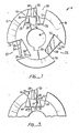
- Fig. 1 is an elevation view of the preferred embodiment of a tool head incorporating the present invention, with a cutting insert mounted in one of the slots;
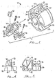
- Fig. 2 is an exploded perspective view of the embodiment of Fig. 1;
- Fig. 3 is a fragmentary view similar to that of Fig. 1 showing radial adjustment of the insert;
- Fig. 4 is an end elevation view of the seat of the embodiment of Fig. 1; and
- Fig. 5 is a side elevation of the seat of the embodiment of Fig. 1.
- The
preferred embodiment 10 of the insert support of the present invention is illustrated generally by way of reference to Figs. 1 and 2 in combination.Insert support 10 includes a rotatable head 12with interior aperture 14for mounting the head on a rotatable, driven shaft.Head 12 includes two joined sections, amain section 16 and a back section 18 which together form the rotatable head. - Three circumferentially spaced slots 20 - 22 are formed in the
main section 16 ofhead 12, and corresponding shallower slots such as 24, 26 are located in back section 18. Each slot 20 - 22 has aflat bottom 28, and a pair ofparallel sides Sides bottom 28 of eachslot 20―22, so that the shape of the slot when viewed axially resembles three sides of a parallelogram.Side 30 andbottom 28 of each slot meet at an acute angle to form what is referred to herein as anacute corner 32.Side 31 andbottom 28 of each slot 20 - 22 meet at an obtuse angle to form what is referred to herein as anobtuse corner 33. Each slot such as 24, 26 in back section 18 has corresponding parallel sides, but is more shallow to form aback face 34. Threadedholes - An
insert seat 38 is mounted within each slot 20 - 22 in themain section 16 ofhead 12. As illustrated by the figures in combination,insert seat 38 has aback face 40 and abottom face 42 which meet at an acute angle atcorner 44, the angle ofcorner 44 being equal to that of the acute angle ofacute corners 32. Eachinsert seat 38 has afront face 46 which is inclined relative toback face 40, and contains arecess 48 in which acutting insert 50 may be supported.Insert seat 38 further includes atransverse portion 52 containing arear face 54 and anaperture 56. - As illustrated in Fig. 1,
insert seat 38 is mounted within one of the slots such asslot 20 with itsback face 40 flush withside 30 so that itsbottom 42 is parallel to orflush with thebottom 28 of the slot. In this position,insert 50 is maintained in a substantially radial posture relative tohead 12.Rear surface 54 is flush with theback face 34 of back section 18, and a screw 58 projecting throughaperture 56 and engaging threadedhole 35 locates the insert seat in position. If radial adjustment is necessary, ashim 60 is placed betweenbottom 42 ofinsert seat 38 andbottom surface 28 of the slot (see Fig. 2 and 3), the thickness of the shim determining the radial position ofinsert 50. - To hold
insert 50 in position, a wedge 62 is provided having a back surface 64 flush withside 31 of the slot, and asplit front surface 66 having atop portion 68 adapted to rest againstinsert 50, and a bottom portion 70 adapted to rest againstseat 38. Wedge 62 has acentral aperture 72, and a screw 74 extends throughaperture 72 and engages threadedhole 36. - To assemble the system of the present invention, the
shim 60 providing the appropriate radial position for the cutting insert is selected, unless it is desirable to locate thebottom 42 ofinsert seat 38 flush with thebottom 28 of the slot. Screw 58 is then used to secureinsert seat 38 in the appropriate slot, and thecutting insert 50 is mounted inrecess 48. Wedge 64 is then inserted, and screw 74 is utilized to force the wedge downwardly, so that theupper portion 68 offront face 66 is pressed againstinsert 50 and holds the insert in position. Because thesides upper portion 68 of thefront face 66 of wedge 62 will contact insert 50 at the same position no matter what radial spacing is given to insertseat 38 to firmly secure the cutting insert in position. Ascutting insert 50 becomes worn during use, alarger shim 60 may be used to maintain the outer diameter of the cutting inserts. - While a preferred embodiment of the invention has been illustrated in detail, it is apparent that modifications and adaptations of that embodiment will occur to those skilled in the art. However, it is to be expressly understood that such modifications and adaptations are within the scope of the present invention, as set forth in the following claims.
Claims (7)
Priority Applications (1)
| Application Number | Priority Date | Filing Date | Title |
|---|---|---|---|
| AT84115658T ATE44668T1 (en) | 1984-02-17 | 1984-12-17 | ADJUSTABLE CUTTING ATTACHMENT. |
Applications Claiming Priority (2)
| Application Number | Priority Date | Filing Date | Title |
|---|---|---|---|
| US06/581,390 US4566826A (en) | 1984-02-17 | 1984-02-17 | Adjustable insert support |
| US581390 | 1984-02-17 |
Publications (2)
| Publication Number | Publication Date |
|---|---|
| EP0154021A1 EP0154021A1 (en) | 1985-09-11 |
| EP0154021B1 true EP0154021B1 (en) | 1989-07-19 |
Family
ID=24325022
Family Applications (1)
| Application Number | Title | Priority Date | Filing Date |
|---|---|---|---|
| EP84115658A Expired EP0154021B1 (en) | 1984-02-17 | 1984-12-17 | Adjustable insert support |
Country Status (5)
| Country | Link |
|---|---|
| US (1) | US4566826A (en) |
| EP (1) | EP0154021B1 (en) |
| JP (1) | JPH0790413B2 (en) |
| AT (1) | ATE44668T1 (en) |
| DE (1) | DE3478997D1 (en) |
Cited By (1)
| Publication number | Priority date | Publication date | Assignee | Title |
|---|---|---|---|---|
| EP1293280A1 (en) | 2001-09-12 | 2003-03-19 | Gühring, Jörg, Dr. | Chip-cutting tool with indexable cutting insert |
Families Citing this family (12)
| Publication number | Priority date | Publication date | Assignee | Title |
|---|---|---|---|---|
| US4744703A (en) * | 1987-02-10 | 1988-05-17 | Manchester Tool Company | Rotary cutter for slotting or cut-off |
| DE8704477U1 (en) * | 1987-03-26 | 1987-05-14 | Gottlieb Gühring KG, 7470 Albstadt | Internally cooled drilling tool consisting of tool spiral and clamping shaft |
| SE460346B (en) * | 1988-06-16 | 1989-10-02 | Sandvik Ab | FRESH TOOLS AND CASSETTE THEREOF |
| US5102269A (en) * | 1989-06-20 | 1992-04-07 | Mitsubishi Materials Corporation | Insert cutter |
| USD376158S (en) | 1993-03-18 | 1996-12-03 | Sandvik Ab | Milling cutter body |
| ES2152014T3 (en) * | 1995-06-06 | 2001-01-16 | Kennametal Inc | CARTRIDGE TYPE STRAWBERRY, HIGH SPEED. |
| SE514029C2 (en) * | 1998-10-27 | 2000-12-11 | Sandvik Ab | Chip separating tool |
| SE512977C2 (en) * | 1998-10-27 | 2000-06-12 | Sandvik Ab | Milling Tools |
| US6702526B2 (en) * | 2002-04-29 | 2004-03-09 | Kennametal Inc. | Cutting tool |
| WO2003092969A1 (en) * | 2002-04-29 | 2003-11-13 | Kennametal Inc. | Cutting tool |
| JP2006082143A (en) * | 2004-09-14 | 2006-03-30 | Tungaloy Corp | Throw away rotary tool |
| EP2773478B1 (en) * | 2011-11-04 | 2016-01-06 | Walter AG | Cartridge with a coarse and a fine adjustment means |
Citations (1)
| Publication number | Priority date | Publication date | Assignee | Title |
|---|---|---|---|---|
| EP0037692A2 (en) * | 1980-04-07 | 1981-10-14 | General Electric Company | Adjustable clamping wedge system for cutting insert of a milling cutter |
Family Cites Families (20)
| Publication number | Priority date | Publication date | Assignee | Title |
|---|---|---|---|---|
| DE48142C (en) * | jos. PALLWEBER in Mannheim | Clock with jumping numbers | ||
| DE136010C (en) * | ||||
| DD48142A (en) * | ||||
| US899608A (en) * | 1907-12-04 | 1908-09-29 | Sidney Newbold | Metal-cutting tool. |
| US2751006A (en) * | 1951-12-12 | 1956-06-19 | United States Steel Corp | Knife-clamping means for rotary shear |
| JPS4428386Y1 (en) * | 1966-09-08 | 1969-11-25 | ||
| US3481015A (en) * | 1967-07-19 | 1969-12-02 | Gerald Q Bogner | Rotary cutting tool |
| DE2043453A1 (en) * | 1970-09-02 | 1972-03-09 | Walter Gmbh Montanwerke | Adjustable holder for indexable inserts for indexable insert milling machines |
| GB1392445A (en) * | 1971-06-03 | 1975-04-30 | Lloyd Ltd Richard | Milling cutter |
| JPS4841758U (en) * | 1971-09-20 | 1973-05-28 | ||
| FR2221221A1 (en) * | 1973-03-16 | 1974-10-11 | Gyrmeto | Metal milling cutter with interchangeable blades - has blades in non-precision machined |
| JPS51103380A (en) * | 1975-03-10 | 1976-09-11 | Dijet Ind Co Ltd | SHIAGEYOSHOMENFURAISUKATSUTAA |
| US4092082A (en) * | 1976-10-12 | 1978-05-30 | The Viking Tool Company | Metal cutting tool with anvil-held indexible and replaceable cutter inserts |
| DD136010A2 (en) * | 1978-01-18 | 1979-06-13 | Guenter Braband | ADJUSTING AND CLAMPING DEVICE FOR CUTTING PLATE SUPPLIER |
| CA1100744A (en) * | 1979-01-19 | 1981-05-12 | Harold W. Lindsay | Holder for pin-type replaceable cutting inserts |
| WO1980002812A1 (en) * | 1979-06-19 | 1980-12-24 | Sandvik Ab | Milling cutter |
| JPS6135372Y2 (en) * | 1980-07-18 | 1986-10-15 | ||
| DE3036527A1 (en) * | 1980-09-27 | 1982-05-13 | Sandvik GmbH, 4000 Düsseldorf | MILLING TOOL |
| US4470731A (en) * | 1981-07-08 | 1984-09-11 | General Electric Company | Milling cutter with adjustable finishing insert |
| US4930935A (en) * | 1988-12-29 | 1990-06-05 | David W. Somero | Screeding apparatus and method |
-
1984
- 1984-02-17 US US06/581,390 patent/US4566826A/en not_active Expired - Lifetime
- 1984-12-17 AT AT84115658T patent/ATE44668T1/en not_active IP Right Cessation
- 1984-12-17 DE DE8484115658T patent/DE3478997D1/en not_active Expired
- 1984-12-17 EP EP84115658A patent/EP0154021B1/en not_active Expired
-
1985
- 1985-02-15 JP JP60026642A patent/JPH0790413B2/en not_active Expired - Lifetime
Patent Citations (1)
| Publication number | Priority date | Publication date | Assignee | Title |
|---|---|---|---|---|
| EP0037692A2 (en) * | 1980-04-07 | 1981-10-14 | General Electric Company | Adjustable clamping wedge system for cutting insert of a milling cutter |
Cited By (1)
| Publication number | Priority date | Publication date | Assignee | Title |
|---|---|---|---|---|
| EP1293280A1 (en) | 2001-09-12 | 2003-03-19 | Gühring, Jörg, Dr. | Chip-cutting tool with indexable cutting insert |
Also Published As
| Publication number | Publication date |
|---|---|
| DE3478997D1 (en) | 1989-08-24 |
| JPH0790413B2 (en) | 1995-10-04 |
| ATE44668T1 (en) | 1989-08-15 |
| JPS60191712A (en) | 1985-09-30 |
| US4566826A (en) | 1986-01-28 |
| EP0154021A1 (en) | 1985-09-11 |
Similar Documents
| Publication | Publication Date | Title |
|---|---|---|
| EP0154021B1 (en) | Adjustable insert support | |
| KR100495190B1 (en) | Axial adjustable milling tool | |
| EP1599306B1 (en) | Cutting tool and cartridge therefor | |
| EP0039539B1 (en) | Floating wedge for use in conjunction with an indexable cutting tool | |
| EP2291258B1 (en) | Cutting tool and cartridge for the same | |
| US8479622B2 (en) | Cutting tool assembly and tool holder therefor | |
| KR100944917B1 (en) | Rotatable cutting tool | |
| US5330297A (en) | Boring tool | |
| EP0627970A1 (en) | Cutting tool with replaceable cutting insert | |
| US3688366A (en) | Tool | |
| US3268977A (en) | Tool holder and insert | |
| EP0042667A2 (en) | Adjustable axial and radial locating wedge assemblies for an indexable insert cutting tool | |
| JP3481839B2 (en) | Tool holder with allocatable inserts secured in insert pockets using fastening screws and clamps | |
| KR20040058303A (en) | Rotatable cutting tool with adjustable cutting insert | |
| EP0027491B1 (en) | Keyless holder for pin-type replaceable cutting inserts | |
| US6695548B2 (en) | Surface milling or angular milling cutter | |
| EP1283082B1 (en) | Rotatable cutting tool | |
| US4744703A (en) | Rotary cutter for slotting or cut-off | |
| US4077735A (en) | Cutting tool and insert assembly | |
| US4195955A (en) | Holder for pin-type replaceable cutting inserts | |
| US4848978A (en) | Milling cutter | |
| JPH08309604A (en) | Exchangable tool substrate | |
| US4288184A (en) | Boring tool | |
| US5322395A (en) | Datum point form tool | |
| GB2042945A (en) | Clamping Cutting Tool Inserts |
Legal Events
| Date | Code | Title | Description |
|---|---|---|---|
| PUAI | Public reference made under article 153(3) epc to a published international application that has entered the european phase |
Free format text: ORIGINAL CODE: 0009012 |
|
| AK | Designated contracting states |
Designated state(s): AT BE CH DE FR GB IT LI LU NL SE |
|
| 17P | Request for examination filed |
Effective date: 19860228 |
|
| 17Q | First examination report despatched |
Effective date: 19870826 |
|
| ITF | It: translation for a ep patent filed | ||
| GRAA | (expected) grant |
Free format text: ORIGINAL CODE: 0009210 |
|
| RAP3 | Party data changed (applicant data changed or rights of an application transferred) |
Owner name: CORBIN, KRESTINE EXECUTRIX OF THE ESTATE OF DICKI |
|
| AK | Designated contracting states |
Kind code of ref document: B1 Designated state(s): AT BE CH DE FR GB IT LI LU NL SE |
|
| REF | Corresponds to: |
Ref document number: 44668 Country of ref document: AT Date of ref document: 19890815 Kind code of ref document: T |
|
| REF | Corresponds to: |
Ref document number: 3478997 Country of ref document: DE Date of ref document: 19890824 |
|
| ET | Fr: translation filed | ||
| PLBE | No opposition filed within time limit |
Free format text: ORIGINAL CODE: 0009261 |
|
| STAA | Information on the status of an ep patent application or granted ep patent |
Free format text: STATUS: NO OPPOSITION FILED WITHIN TIME LIMIT |
|
| 26N | No opposition filed | ||
| ITTA | It: last paid annual fee | ||
| PGFP | Annual fee paid to national office [announced via postgrant information from national office to epo] |
Ref country code: CH Payment date: 19931112 Year of fee payment: 10 |
|
| PGFP | Annual fee paid to national office [announced via postgrant information from national office to epo] |
Ref country code: LU Payment date: 19931116 Year of fee payment: 10 |
|
| PGFP | Annual fee paid to national office [announced via postgrant information from national office to epo] |
Ref country code: AT Payment date: 19931117 Year of fee payment: 10 |
|
| EPTA | Lu: last paid annual fee | ||
| PGFP | Annual fee paid to national office [announced via postgrant information from national office to epo] |
Ref country code: BE Payment date: 19941124 Year of fee payment: 11 |
|
| PG25 | Lapsed in a contracting state [announced via postgrant information from national office to epo] |
Ref country code: LU Free format text: LAPSE BECAUSE OF NON-PAYMENT OF DUE FEES Effective date: 19941217 Ref country code: AT Effective date: 19941217 |
|
| PG25 | Lapsed in a contracting state [announced via postgrant information from national office to epo] |
Ref country code: LI Effective date: 19941231 Ref country code: CH Effective date: 19941231 |
|
| PGFP | Annual fee paid to national office [announced via postgrant information from national office to epo] |
Ref country code: NL Payment date: 19941231 Year of fee payment: 11 |
|
| EAL | Se: european patent in force in sweden |
Ref document number: 84115658.1 |
|
| REG | Reference to a national code |
Ref country code: CH Ref legal event code: PL |
|
| PG25 | Lapsed in a contracting state [announced via postgrant information from national office to epo] |
Ref country code: BE Effective date: 19951231 |
|
| BERE | Be: lapsed |
Owner name: CORBIN KRESTINE EXECUTRIX OF THE ESTATE OF DICKI Effective date: 19951231 |
|
| PG25 | Lapsed in a contracting state [announced via postgrant information from national office to epo] |
Ref country code: NL Effective date: 19960701 |
|
| NLV4 | Nl: lapsed or anulled due to non-payment of the annual fee |
Effective date: 19960701 |
|
| REG | Reference to a national code |
Ref country code: GB Ref legal event code: IF02 |
|
| PGFP | Annual fee paid to national office [announced via postgrant information from national office to epo] |
Ref country code: GB Payment date: 20031210 Year of fee payment: 20 |
|
| PGFP | Annual fee paid to national office [announced via postgrant information from national office to epo] |
Ref country code: FR Payment date: 20031218 Year of fee payment: 20 |
|
| PGFP | Annual fee paid to national office [announced via postgrant information from national office to epo] |
Ref country code: SE Payment date: 20031219 Year of fee payment: 20 |
|
| PGFP | Annual fee paid to national office [announced via postgrant information from national office to epo] |
Ref country code: DE Payment date: 20040202 Year of fee payment: 20 |
|
| PG25 | Lapsed in a contracting state [announced via postgrant information from national office to epo] |
Ref country code: GB Free format text: LAPSE BECAUSE OF EXPIRATION OF PROTECTION Effective date: 20041216 |
|
| REG | Reference to a national code |
Ref country code: GB Ref legal event code: PE20 |
|
| EUG | Se: european patent has lapsed | ||
| EUG | Se: european patent has lapsed |