EP0156588B1 - Automatisierter Polypeptidsyntheseapparat - Google Patents
Automatisierter Polypeptidsyntheseapparat Download PDFInfo
- Publication number
- EP0156588B1 EP0156588B1 EP85301729A EP85301729A EP0156588B1 EP 0156588 B1 EP0156588 B1 EP 0156588B1 EP 85301729 A EP85301729 A EP 85301729A EP 85301729 A EP85301729 A EP 85301729A EP 0156588 B1 EP0156588 B1 EP 0156588B1
- Authority
- EP
- European Patent Office
- Prior art keywords
- vessel
- amino acid
- reaction vessel
- tube
- activator
- Prior art date
- Legal status (The legal status is an assumption and is not a legal conclusion. Google has not performed a legal analysis and makes no representation as to the accuracy of the status listed.)
- Expired - Lifetime
Links
- 108090000765 processed proteins & peptides Proteins 0.000 title claims description 87
- 102000004196 processed proteins & peptides Human genes 0.000 title claims description 16
- 229920001184 polypeptide Polymers 0.000 title claims description 7
- 230000015572 biosynthetic process Effects 0.000 title description 41
- 238000003786 synthesis reaction Methods 0.000 title description 37
- 150000001413 amino acids Chemical class 0.000 claims description 121
- 238000006243 chemical reaction Methods 0.000 claims description 103
- 239000012190 activator Substances 0.000 claims description 70
- 238000005859 coupling reaction Methods 0.000 claims description 44
- 238000012546 transfer Methods 0.000 claims description 44
- 230000008878 coupling Effects 0.000 claims description 42
- 238000010168 coupling process Methods 0.000 claims description 42
- 239000011347 resin Substances 0.000 claims description 40
- 229920005989 resin Polymers 0.000 claims description 40
- 239000002904 solvent Substances 0.000 claims description 32
- 230000004913 activation Effects 0.000 claims description 28
- 239000007788 liquid Substances 0.000 claims description 27
- 239000007789 gas Substances 0.000 claims description 26
- 239000000463 material Substances 0.000 claims description 14
- 239000012528 membrane Substances 0.000 claims description 13
- 239000000758 substrate Substances 0.000 claims description 10
- 238000013019 agitation Methods 0.000 claims description 9
- 238000004519 manufacturing process Methods 0.000 claims description 8
- 230000007704 transition Effects 0.000 claims description 8
- 230000033001 locomotion Effects 0.000 claims description 7
- 239000000126 substance Substances 0.000 claims description 7
- 238000010532 solid phase synthesis reaction Methods 0.000 claims description 6
- 238000000605 extraction Methods 0.000 claims description 5
- 230000009471 action Effects 0.000 claims description 3
- 238000005054 agglomeration Methods 0.000 claims description 3
- 230000002776 aggregation Effects 0.000 claims description 3
- 230000003213 activating effect Effects 0.000 claims description 2
- 238000006467 substitution reaction Methods 0.000 claims description 2
- 239000012858 resilient material Substances 0.000 claims 1
- YMWUJEATGCHHMB-UHFFFAOYSA-N Dichloromethane Chemical compound ClCCl YMWUJEATGCHHMB-UHFFFAOYSA-N 0.000 description 144
- 229940024606 amino acid Drugs 0.000 description 104
- 235000001014 amino acid Nutrition 0.000 description 100
- 230000006870 function Effects 0.000 description 52
- ZMXDDKWLCZADIW-UHFFFAOYSA-N N,N-Dimethylformamide Chemical compound CN(C)C=O ZMXDDKWLCZADIW-UHFFFAOYSA-N 0.000 description 45
- 238000001994 activation Methods 0.000 description 22
- 238000000034 method Methods 0.000 description 21
- 150000008064 anhydrides Chemical class 0.000 description 19
- 239000012530 fluid Substances 0.000 description 16
- QOSSAOTZNIDXMA-UHFFFAOYSA-N Dicylcohexylcarbodiimide Chemical compound C1CCCCC1N=C=NC1CCCCC1 QOSSAOTZNIDXMA-UHFFFAOYSA-N 0.000 description 13
- 230000008569 process Effects 0.000 description 11
- 238000005406 washing Methods 0.000 description 11
- 230000001934 delay Effects 0.000 description 10
- 238000010647 peptide synthesis reaction Methods 0.000 description 10
- 125000003178 carboxy group Chemical group [H]OC(*)=O 0.000 description 8
- 239000000203 mixture Substances 0.000 description 8
- JMTMSDXUXJISAY-UHFFFAOYSA-N 2H-benzotriazol-4-ol Chemical compound OC1=CC=CC2=C1N=NN2 JMTMSDXUXJISAY-UHFFFAOYSA-N 0.000 description 7
- 239000003153 chemical reaction reagent Substances 0.000 description 7
- 230000000694 effects Effects 0.000 description 7
- NPZTUJOABDZTLV-UHFFFAOYSA-N hydroxybenzotriazole Substances O=C1C=CC=C2NNN=C12 NPZTUJOABDZTLV-UHFFFAOYSA-N 0.000 description 7
- 239000002244 precipitate Substances 0.000 description 7
- 238000003260 vortexing Methods 0.000 description 7
- 239000011521 glass Substances 0.000 description 6
- 239000007790 solid phase Substances 0.000 description 6
- 239000002699 waste material Substances 0.000 description 6
- 238000013459 approach Methods 0.000 description 5
- 230000008859 change Effects 0.000 description 5
- 238000010511 deprotection reaction Methods 0.000 description 5
- 238000001514 detection method Methods 0.000 description 5
- 239000012071 phase Substances 0.000 description 5
- 230000003068 static effect Effects 0.000 description 5
- -1 t-butyloxycarbonyl group Chemical group 0.000 description 5
- JGFZNNIVVJXRND-UHFFFAOYSA-N N,N-Diisopropylethylamine (DIPEA) Chemical compound CCN(C(C)C)C(C)C JGFZNNIVVJXRND-UHFFFAOYSA-N 0.000 description 4
- 238000007792 addition Methods 0.000 description 4
- 239000006227 byproduct Substances 0.000 description 4
- 238000009826 distribution Methods 0.000 description 4
- ZDXPYRJPNDTMRX-UHFFFAOYSA-N glutamine Natural products OC(=O)C(N)CCC(N)=O ZDXPYRJPNDTMRX-UHFFFAOYSA-N 0.000 description 4
- 238000006386 neutralization reaction Methods 0.000 description 4
- 239000012508 resin bead Substances 0.000 description 4
- 238000000926 separation method Methods 0.000 description 4
- OKKJLVBELUTLKV-UHFFFAOYSA-N Methanol Chemical compound OC OKKJLVBELUTLKV-UHFFFAOYSA-N 0.000 description 3
- 230000006229 amino acid addition Effects 0.000 description 3
- 238000009835 boiling Methods 0.000 description 3
- 230000001419 dependent effect Effects 0.000 description 3
- 239000000047 product Substances 0.000 description 3
- 125000006239 protecting group Chemical group 0.000 description 3
- 238000005070 sampling Methods 0.000 description 3
- 238000012360 testing method Methods 0.000 description 3
- OBUGXZVDQXDGTF-VEJNRXSDSA-N (3s)-3-[[(2s,3s)-2-[[(2s)-2-[[(2s)-2-[[(2s)-5-amino-2-[[(2s)-2-amino-3-methylbutanoyl]amino]-5-oxopentanoyl]amino]propanoyl]amino]propanoyl]amino]-3-methylpentanoyl]amino]-4-[[(2s)-1-[[(2s,3s)-1-[[(2s)-4-amino-1-(carboxymethylamino)-1,4-dioxobutan-2-yl]am Chemical compound CC(C)[C@H](N)C(=O)N[C@@H](CCC(N)=O)C(=O)N[C@@H](C)C(=O)N[C@@H](C)C(=O)N[C@@H]([C@@H](C)CC)C(=O)N[C@@H](CC(O)=O)C(=O)N[C@H](C(=O)N[C@@H]([C@@H](C)CC)C(=O)N[C@@H](CC(N)=O)C(=O)NCC(O)=O)CC1=CC=C(O)C=C1 OBUGXZVDQXDGTF-VEJNRXSDSA-N 0.000 description 2
- XKRFYHLGVUSROY-UHFFFAOYSA-N Argon Chemical compound [Ar] XKRFYHLGVUSROY-UHFFFAOYSA-N 0.000 description 2
- DCXYFEDJOCDNAF-UHFFFAOYSA-N Asparagine Natural products OC(=O)C(N)CC(N)=O DCXYFEDJOCDNAF-UHFFFAOYSA-N 0.000 description 2
- IJGRMHOSHXDMSA-UHFFFAOYSA-N Atomic nitrogen Chemical compound N#N IJGRMHOSHXDMSA-UHFFFAOYSA-N 0.000 description 2
- DCXYFEDJOCDNAF-REOHCLBHSA-N L-asparagine Chemical compound OC(=O)[C@@H](N)CC(N)=O DCXYFEDJOCDNAF-REOHCLBHSA-N 0.000 description 2
- ZDXPYRJPNDTMRX-VKHMYHEASA-N L-glutamine Chemical compound OC(=O)[C@@H](N)CCC(N)=O ZDXPYRJPNDTMRX-VKHMYHEASA-N 0.000 description 2
- DTQVDTLACAAQTR-UHFFFAOYSA-N Trifluoroacetic acid Chemical compound OC(=O)C(F)(F)F DTQVDTLACAAQTR-UHFFFAOYSA-N 0.000 description 2
- 239000002253 acid Substances 0.000 description 2
- 108010038289 acyl carrier protein (65-74) Proteins 0.000 description 2
- 229960001230 asparagine Drugs 0.000 description 2
- 235000009582 asparagine Nutrition 0.000 description 2
- 230000008901 benefit Effects 0.000 description 2
- 238000004364 calculation method Methods 0.000 description 2
- 238000004140 cleaning Methods 0.000 description 2
- 238000001704 evaporation Methods 0.000 description 2
- 230000008020 evaporation Effects 0.000 description 2
- 238000011068 loading method Methods 0.000 description 2
- 238000002156 mixing Methods 0.000 description 2
- 230000000737 periodic effect Effects 0.000 description 2
- 238000002360 preparation method Methods 0.000 description 2
- 230000035484 reaction time Effects 0.000 description 2
- 238000003860 storage Methods 0.000 description 2
- 238000013022 venting Methods 0.000 description 2
- 239000011800 void material Substances 0.000 description 2
- ASOKPJOREAFHNY-UHFFFAOYSA-N 1-Hydroxybenzotriazole Chemical compound C1=CC=C2N(O)N=NC2=C1 ASOKPJOREAFHNY-UHFFFAOYSA-N 0.000 description 1
- NGNBDVOYPDDBFK-UHFFFAOYSA-N 2-[2,4-di(pentan-2-yl)phenoxy]acetyl chloride Chemical compound CCCC(C)C1=CC=C(OCC(Cl)=O)C(C(C)CCC)=C1 NGNBDVOYPDDBFK-UHFFFAOYSA-N 0.000 description 1
- 239000004475 Arginine Substances 0.000 description 1
- 102000004190 Enzymes Human genes 0.000 description 1
- 108090000790 Enzymes Proteins 0.000 description 1
- LFQSCWFLJHTTHZ-UHFFFAOYSA-N Ethanol Chemical compound CCO LFQSCWFLJHTTHZ-UHFFFAOYSA-N 0.000 description 1
- ODKSFYDXXFIFQN-BYPYZUCNSA-P L-argininium(2+) Chemical compound NC(=[NH2+])NCCC[C@H]([NH3+])C(O)=O ODKSFYDXXFIFQN-BYPYZUCNSA-P 0.000 description 1
- 239000004677 Nylon Substances 0.000 description 1
- 239000004698 Polyethylene Substances 0.000 description 1
- 229910000831 Steel Inorganic materials 0.000 description 1
- 238000005299 abrasion Methods 0.000 description 1
- 125000003277 amino group Chemical group 0.000 description 1
- 230000003042 antagnostic effect Effects 0.000 description 1
- ODKSFYDXXFIFQN-UHFFFAOYSA-N arginine Natural products OC(=O)C(N)CCCNC(N)=N ODKSFYDXXFIFQN-UHFFFAOYSA-N 0.000 description 1
- 229910052786 argon Inorganic materials 0.000 description 1
- 238000003491 array Methods 0.000 description 1
- 238000011097 chromatography purification Methods 0.000 description 1
- 238000010276 construction Methods 0.000 description 1
- 239000007822 coupling agent Substances 0.000 description 1
- 230000003413 degradative effect Effects 0.000 description 1
- 238000000151 deposition Methods 0.000 description 1
- 238000011161 development Methods 0.000 description 1
- 238000010586 diagram Methods 0.000 description 1
- 238000004090 dissolution Methods 0.000 description 1
- 239000003814 drug Substances 0.000 description 1
- 150000002148 esters Chemical class 0.000 description 1
- NBVXSUQYWXRMNV-UHFFFAOYSA-N fluoromethane Chemical compound FC NBVXSUQYWXRMNV-UHFFFAOYSA-N 0.000 description 1
- 229920002313 fluoropolymer Polymers 0.000 description 1
- 239000005556 hormone Substances 0.000 description 1
- 229940088597 hormone Drugs 0.000 description 1
- 230000006872 improvement Effects 0.000 description 1
- 238000011065 in-situ storage Methods 0.000 description 1
- 238000010348 incorporation Methods 0.000 description 1
- 238000007373 indentation Methods 0.000 description 1
- 239000011261 inert gas Substances 0.000 description 1
- 239000003112 inhibitor Substances 0.000 description 1
- 230000003993 interaction Effects 0.000 description 1
- 238000011835 investigation Methods 0.000 description 1
- 238000002955 isolation Methods 0.000 description 1
- 238000005259 measurement Methods 0.000 description 1
- 230000004048 modification Effects 0.000 description 1
- 238000012986 modification Methods 0.000 description 1
- 229910052757 nitrogen Inorganic materials 0.000 description 1
- 229920001778 nylon Polymers 0.000 description 1
- 238000005457 optimization Methods 0.000 description 1
- 230000008520 organization Effects 0.000 description 1
- 239000002245 particle Substances 0.000 description 1
- ISWSIDIOOBJBQZ-UHFFFAOYSA-N phenol group Chemical group C1(=CC=CC=C1)O ISWSIDIOOBJBQZ-UHFFFAOYSA-N 0.000 description 1
- 239000004033 plastic Substances 0.000 description 1
- 229920003023 plastic Polymers 0.000 description 1
- 239000003880 polar aprotic solvent Substances 0.000 description 1
- 239000002798 polar solvent Substances 0.000 description 1
- 229920000573 polyethylene Polymers 0.000 description 1
- 229920000642 polymer Polymers 0.000 description 1
- 238000001556 precipitation Methods 0.000 description 1
- 235000018102 proteins Nutrition 0.000 description 1
- 108090000623 proteins and genes Proteins 0.000 description 1
- 102000004169 proteins and genes Human genes 0.000 description 1
- 238000010926 purge Methods 0.000 description 1
- 238000011155 quantitative monitoring Methods 0.000 description 1
- 230000006340 racemization Effects 0.000 description 1
- 230000009467 reduction Effects 0.000 description 1
- 230000003252 repetitive effect Effects 0.000 description 1
- 230000004044 response Effects 0.000 description 1
- 229910000679 solder Inorganic materials 0.000 description 1
- 238000003746 solid phase reaction Methods 0.000 description 1
- 238000000638 solvent extraction Methods 0.000 description 1
- 239000010959 steel Substances 0.000 description 1
- 230000002194 synthesizing effect Effects 0.000 description 1
- WROMPOXWARCANT-UHFFFAOYSA-N tfa trifluoroacetic acid Chemical compound OC(=O)C(F)(F)F.OC(=O)C(F)(F)F WROMPOXWARCANT-UHFFFAOYSA-N 0.000 description 1
- 229960005486 vaccine Drugs 0.000 description 1
- 238000011179 visual inspection Methods 0.000 description 1
- 230000003245 working effect Effects 0.000 description 1
Images


Classifications
-
- C—CHEMISTRY; METALLURGY
- C07—ORGANIC CHEMISTRY
- C07K—PEPTIDES
- C07K1/00—General methods for the preparation of peptides, i.e. processes for the organic chemical preparation of peptides or proteins of any length
- C07K1/04—General methods for the preparation of peptides, i.e. processes for the organic chemical preparation of peptides or proteins of any length on carriers
- C07K1/045—General methods for the preparation of peptides, i.e. processes for the organic chemical preparation of peptides or proteins of any length on carriers using devices to improve synthesis, e.g. reactors, special vessels
-
- B—PERFORMING OPERATIONS; TRANSPORTING
- B01—PHYSICAL OR CHEMICAL PROCESSES OR APPARATUS IN GENERAL
- B01J—CHEMICAL OR PHYSICAL PROCESSES, e.g. CATALYSIS OR COLLOID CHEMISTRY; THEIR RELEVANT APPARATUS
- B01J19/00—Chemical, physical or physico-chemical processes in general; Their relevant apparatus
- B01J19/0046—Sequential or parallel reactions, e.g. for the synthesis of polypeptides or polynucleotides; Apparatus and devices for combinatorial chemistry or for making molecular arrays
-
- B—PERFORMING OPERATIONS; TRANSPORTING
- B01—PHYSICAL OR CHEMICAL PROCESSES OR APPARATUS IN GENERAL
- B01J—CHEMICAL OR PHYSICAL PROCESSES, e.g. CATALYSIS OR COLLOID CHEMISTRY; THEIR RELEVANT APPARATUS
- B01J2219/00—Chemical, physical or physico-chemical processes in general; Their relevant apparatus
- B01J2219/00274—Sequential or parallel reactions; Apparatus and devices for combinatorial chemistry or for making arrays; Chemical library technology
- B01J2219/00277—Apparatus
- B01J2219/00279—Features relating to reactor vessels
- B01J2219/00281—Individual reactor vessels
- B01J2219/00286—Reactor vessels with top and bottom openings
-
- B—PERFORMING OPERATIONS; TRANSPORTING
- B01—PHYSICAL OR CHEMICAL PROCESSES OR APPARATUS IN GENERAL
- B01J—CHEMICAL OR PHYSICAL PROCESSES, e.g. CATALYSIS OR COLLOID CHEMISTRY; THEIR RELEVANT APPARATUS
- B01J2219/00—Chemical, physical or physico-chemical processes in general; Their relevant apparatus
- B01J2219/00274—Sequential or parallel reactions; Apparatus and devices for combinatorial chemistry or for making arrays; Chemical library technology
- B01J2219/00277—Apparatus
- B01J2219/00351—Means for dispensing and evacuation of reagents
- B01J2219/00389—Feeding through valves
-
- B—PERFORMING OPERATIONS; TRANSPORTING
- B01—PHYSICAL OR CHEMICAL PROCESSES OR APPARATUS IN GENERAL
- B01J—CHEMICAL OR PHYSICAL PROCESSES, e.g. CATALYSIS OR COLLOID CHEMISTRY; THEIR RELEVANT APPARATUS
- B01J2219/00—Chemical, physical or physico-chemical processes in general; Their relevant apparatus
- B01J2219/00274—Sequential or parallel reactions; Apparatus and devices for combinatorial chemistry or for making arrays; Chemical library technology
- B01J2219/00277—Apparatus
- B01J2219/00479—Means for mixing reactants or products in the reaction vessels
- B01J2219/00484—Means for mixing reactants or products in the reaction vessels by shaking, vibrating or oscillating of the reaction vessels
-
- B—PERFORMING OPERATIONS; TRANSPORTING
- B01—PHYSICAL OR CHEMICAL PROCESSES OR APPARATUS IN GENERAL
- B01J—CHEMICAL OR PHYSICAL PROCESSES, e.g. CATALYSIS OR COLLOID CHEMISTRY; THEIR RELEVANT APPARATUS
- B01J2219/00—Chemical, physical or physico-chemical processes in general; Their relevant apparatus
- B01J2219/00274—Sequential or parallel reactions; Apparatus and devices for combinatorial chemistry or for making arrays; Chemical library technology
- B01J2219/00277—Apparatus
- B01J2219/00479—Means for mixing reactants or products in the reaction vessels
- B01J2219/00488—Means for mixing reactants or products in the reaction vessels by rotation of the reaction vessels
- B01J2219/0049—Means for mixing reactants or products in the reaction vessels by rotation of the reaction vessels by centrifugation
-
- B—PERFORMING OPERATIONS; TRANSPORTING
- B01—PHYSICAL OR CHEMICAL PROCESSES OR APPARATUS IN GENERAL
- B01J—CHEMICAL OR PHYSICAL PROCESSES, e.g. CATALYSIS OR COLLOID CHEMISTRY; THEIR RELEVANT APPARATUS
- B01J2219/00—Chemical, physical or physico-chemical processes in general; Their relevant apparatus
- B01J2219/00274—Sequential or parallel reactions; Apparatus and devices for combinatorial chemistry or for making arrays; Chemical library technology
- B01J2219/00277—Apparatus
- B01J2219/00495—Means for heating or cooling the reaction vessels
-
- B—PERFORMING OPERATIONS; TRANSPORTING
- B01—PHYSICAL OR CHEMICAL PROCESSES OR APPARATUS IN GENERAL
- B01J—CHEMICAL OR PHYSICAL PROCESSES, e.g. CATALYSIS OR COLLOID CHEMISTRY; THEIR RELEVANT APPARATUS
- B01J2219/00—Chemical, physical or physico-chemical processes in general; Their relevant apparatus
- B01J2219/00274—Sequential or parallel reactions; Apparatus and devices for combinatorial chemistry or for making arrays; Chemical library technology
- B01J2219/00277—Apparatus
- B01J2219/00497—Features relating to the solid phase supports
- B01J2219/005—Beads
-
- B—PERFORMING OPERATIONS; TRANSPORTING
- B01—PHYSICAL OR CHEMICAL PROCESSES OR APPARATUS IN GENERAL
- B01J—CHEMICAL OR PHYSICAL PROCESSES, e.g. CATALYSIS OR COLLOID CHEMISTRY; THEIR RELEVANT APPARATUS
- B01J2219/00—Chemical, physical or physico-chemical processes in general; Their relevant apparatus
- B01J2219/00274—Sequential or parallel reactions; Apparatus and devices for combinatorial chemistry or for making arrays; Chemical library technology
- B01J2219/00583—Features relative to the processes being carried out
- B01J2219/0059—Sequential processes
-
- B—PERFORMING OPERATIONS; TRANSPORTING
- B01—PHYSICAL OR CHEMICAL PROCESSES OR APPARATUS IN GENERAL
- B01J—CHEMICAL OR PHYSICAL PROCESSES, e.g. CATALYSIS OR COLLOID CHEMISTRY; THEIR RELEVANT APPARATUS
- B01J2219/00—Chemical, physical or physico-chemical processes in general; Their relevant apparatus
- B01J2219/00274—Sequential or parallel reactions; Apparatus and devices for combinatorial chemistry or for making arrays; Chemical library technology
- B01J2219/00583—Features relative to the processes being carried out
- B01J2219/00596—Solid-phase processes
-
- B—PERFORMING OPERATIONS; TRANSPORTING
- B01—PHYSICAL OR CHEMICAL PROCESSES OR APPARATUS IN GENERAL
- B01J—CHEMICAL OR PHYSICAL PROCESSES, e.g. CATALYSIS OR COLLOID CHEMISTRY; THEIR RELEVANT APPARATUS
- B01J2219/00—Chemical, physical or physico-chemical processes in general; Their relevant apparatus
- B01J2219/00274—Sequential or parallel reactions; Apparatus and devices for combinatorial chemistry or for making arrays; Chemical library technology
- B01J2219/0068—Means for controlling the apparatus of the process
- B01J2219/00686—Automatic
- B01J2219/00689—Automatic using computers
-
- B—PERFORMING OPERATIONS; TRANSPORTING
- B01—PHYSICAL OR CHEMICAL PROCESSES OR APPARATUS IN GENERAL
- B01J—CHEMICAL OR PHYSICAL PROCESSES, e.g. CATALYSIS OR COLLOID CHEMISTRY; THEIR RELEVANT APPARATUS
- B01J2219/00—Chemical, physical or physico-chemical processes in general; Their relevant apparatus
- B01J2219/00274—Sequential or parallel reactions; Apparatus and devices for combinatorial chemistry or for making arrays; Chemical library technology
- B01J2219/0068—Means for controlling the apparatus of the process
- B01J2219/00695—Synthesis control routines, e.g. using computer programs
-
- B—PERFORMING OPERATIONS; TRANSPORTING
- B01—PHYSICAL OR CHEMICAL PROCESSES OR APPARATUS IN GENERAL
- B01J—CHEMICAL OR PHYSICAL PROCESSES, e.g. CATALYSIS OR COLLOID CHEMISTRY; THEIR RELEVANT APPARATUS
- B01J2219/00—Chemical, physical or physico-chemical processes in general; Their relevant apparatus
- B01J2219/00274—Sequential or parallel reactions; Apparatus and devices for combinatorial chemistry or for making arrays; Chemical library technology
- B01J2219/00718—Type of compounds synthesised
- B01J2219/0072—Organic compounds
- B01J2219/00725—Peptides
-
- C—CHEMISTRY; METALLURGY
- C40—COMBINATORIAL TECHNOLOGY
- C40B—COMBINATORIAL CHEMISTRY; LIBRARIES, e.g. CHEMICAL LIBRARIES
- C40B40/00—Libraries per se, e.g. arrays, mixtures
- C40B40/04—Libraries containing only organic compounds
- C40B40/10—Libraries containing peptides or polypeptides, or derivatives thereof
-
- C—CHEMISTRY; METALLURGY
- C40—COMBINATORIAL TECHNOLOGY
- C40B—COMBINATORIAL CHEMISTRY; LIBRARIES, e.g. CHEMICAL LIBRARIES
- C40B60/00—Apparatus specially adapted for use in combinatorial chemistry or with libraries
- C40B60/14—Apparatus specially adapted for use in combinatorial chemistry or with libraries for creating libraries
Definitions
- This invention relates to apparatus for the automated synthesis of polypeptides, and particularly to apparatus for automatically pre-forming activated species of (alpha-amino protected) amino acids immediately prior to introduction into solid phase synthesis reactions.
- solid phase peptide synthesis begins with the covalent attachment of the carboxyl end of an (alpha-amino protected) first amino acid in the peptide sequence through an organic linker to an insoluble resin bead (typically 25-300 ⁇ m in diameter), illustrated by:
- a general cycle of synthesis then consists of deprotection of the resin bound alpha-amino group, washing (and neutralization if necessary), followed by reaction with with some carboxyl activated form of the next (alpha-amino protected) amino acid to yield: Repetition of the cycle to the n th amino acid then yields:
- the link of the peptide to its polymer support is cleaved, and the dissolved peptide is separated from the insoluble resin and purified.
- the by-products of peptide synthesis consist of a complex mixture of molecules which are chemically similar to the target peptide. Chromatographic purification can be extraordinarily difficult and time consuming as the relative amount of by-product molecules begins to exceed about 25%.
- step yield is dependent on many factors such as the nature and quality of the protected amino acids, solvent purity, chemical integrity of the resin, the chemical nature of the organic linker, the form of the activated carboxyl of the amino acid, efficiency of the wash steps, the synthesis protocol, and in some instances the identity of an amino acid in conjunction with a particular sequence segment to which it is being added.
- Prior art peptide synthesizers operate essentially as "washing machines" which automate the monotonous fluid manipulations of deprotection, addition of coupling agent, and washing. In no case do existing commercial peptide synthesizers form an activated amino acid species outside or independent of the reaction vessel. Typically, protected amino acid and DCC are added to the reaction vessel containing the resin bound, incipient peptide chain so that activation of the amino acid occurs in the presence of the deprotected alpha-amino group. This approach both limits the possibility (or feasibility) of optimizing activation conditions for individual amino acids and requires that any modification of activation conditions be done in the presence of the deprotected alpha-amino group and the growing, resin-bound peptide chain.
- the present invention provides an apparatus for the manufacture of peptides by solid phase synthesis comprising: activation means for receiving protected amino acids, including a common activation vessel in which to activate each of the amino acids and solvent coupling medium substitution means; the reaction vessel for accommodating the substrate in an appropriate solvent; transfer means connected to the activation means and to the reaction vessel for transferring materials used in the apparatus; and computer means connected to the transfer means, for automatically controlling the transfer of successive aliquots of amino acids, in a preselected sequence into the activation means; the transfer of corresponding, successive aliquots of activating medium into the activation means; the transfer of successive aliquots of activated amino acids so produced, in the preselected sequence into the reaction vessel so as to introduce to the substrate activated amino acids, one at a time, in the preselected sequence.
- an apparatus for automatically constructing a polypeptide of high purity, up to 50 amino acids in length, using only single couplings.
- the apparatus includes an activation system for receiving protected amino acids, one kind at a time, having a common vessel (an activator vessel) in which to activate each of the amino acids in the order received to form a sequence of aliquots of activated species of each of the amino acids, each aliquot containing one kind of amino acid and the sequence of aliquots of each kind of amino acid being in the order desired in the peptide.
- a reaction vessel for containing a resin used in solid-phase peptide synthesis for attaching a peptide chain thereto.
- a transfer system is also provided, which operates under control of a computer, to transfer the activated species from the activation system to the reaction vessel and to transfer amino acids, reagents, gases, and solvents from one part of the apparatus to another.
- the activator system also includes a temperature controlled concentrator vessel in which an activator solvent, which is used in the activator vessel when creating the activated species of the amino acid, is replaced by a coupling solvent to enhance the coupling of the activated species to the peptide chain in the reaction vessel.
- This replacement is accomplished a short period of time (typically less than thirty minutes) before the activated amino acid is introduced into the reaction vessel, by adding the coupling solvent to the concentrator vessel together with the activated species and the activator solvent, and sparging gas through the resulting solution to selectively evaporate the activator solvent, activator solvent being chosen with a boiling point lower than the boiling point of the coupling solvent.
- the concentrator is heated as necessary to replace heat lost by evaporation.
- a vortexer for affecting total washing of materials in the reaction vessel and the reaction vessel itself, an automated peptide resin sampling system, and an autodelivery system for providing individual containers of amino acid to the synthesizer in the order desired in the peptide sequence.
- a specialized container for use in the autodelivery system is provided which has a vee-shaped bottom in order to permit extraction of as much amino acid as is practicable which permits precise control over stoichiometry.
- a liquid sensor system is also included to monitor transitions between gases and liquids in specific tubes in the synthesizer in order to provide input signals to the computer system for control purposes.
- the computer system software which controls the operation of the synthesizer is organized according to a series of menus which allows the user of the system to select individual cycles of operation for each vessel in the synthesizer.
- each cycle can be user-defined into a series of functions, each of which corresponds to a standard set of instructions for individual valves and other switched systems associated with the synthesizer.
- the user can define alternative individual functions as well.
- the preferred mode of the synthesis takes place primarily in three phases.
- Symmetic anhydrides are extremely effective, activated carboxyl forms of amino acids, since their couplings are substantially free of racemization in the absence of base and since quantitative single couplings are usually assured for most amino acid additions, with the exception of asparagine, glutamine, and arginine--each of which is more efficiently coupled by an alternative activation method which will be discussed later.
- the generally quantitative nature of couplings with symmetric anhydrides makes them most useful where automated synthesis precludes convenient step by step quantitative monitoring.
- the apparatus herein described automatically synthesizes symmetric anhydrides immediately before incorporation into the peptide chain. Because of the marginal stability of symmetric anhydrides and their difficulty of isolation in pure form, their use in the past has been limited to manual preformation followed by introduction into an automated synthesis machine.
- the procedure for synthesizing pre-formed symmetric anhydrides consists of reacting 0.5 equivalents of dicyclohexylcarbodiimide (DCC) with 1.0 equivalent of protected amino acid in dichloromethane (DCM) according to the equation: dichloromethane being an optimal solvent for the synthesis of PSA's, particularly where the alpha-amino protecting group P is the t-butyloxycarbonyl group (t-BOC).
- the DCU formed in the reaction, however, is very insoluble in dichloromethane and precipitates during the PSA reaction.
- the PSA/DCM solution is filtered away from the DCU precipitate, and the second, or concentration phase is begun.
- the DCM is removed and replaced by polar aprotic solvent, preferably N,N-dimethylformamide (DMF), to enhance coupling efficiency during later solid phase reactions.
- polar aprotic solvent preferably N,N-dimethylformamide (DMF)
- DMF N,N-dimethylformamide
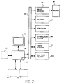
- Figures 1A, 1B, 2 and 3 show respectively a fluid delivery system, for routing the various amino acids, reagents, solvents and gases throughout the apparatus; a computer system for effecting automatic control over the numerous switches which control the valves, sensors, temperature of certain vessels, and motors in the apparatus; and an autodelivery system for transporting protected amino acids to the apparatus in the order desired in the peptide sequence.
- the fluid delivery system includes of three primary vessels: an activator vessel 11, where the PSA is formed: a concentrator vessel 13, where the PSA/DCM solution from the activator vessel is transferred so that DCM may be replaced by DMF to enhance coupling; and a reaction vessel 15 which contains the growing resin-bound peptide chain.
- Activator vessel 11 is typically cylindrical, about 40 ml in volume, and is preferably constructed of glass in order for the operator of the device to visually inspect the progress of reactions or cleaning cycles. At the bottom of the activator vessel is a glass frit 17 of coarse poresize which is used to filter the DCU precipitate from the PSA/DCM solution when transferring the solution to the concentrator vessel 13. Activator vessel 11 also contains an overhead nozzle 19 which faces upward in order to achieve a total washdown of the headspace and walls after each amino acid is transferred out of the vessel. Activator 11 is coupled to the autodelivery system and to various gases and reagents as shown via a valve block 23, which is an assembly of zero dead volume valves such as that described in U.S.
- Valve block 23 is operated under the control of the computer system, as are all other valve blocks and gas valves in the apparatus.
- Activator 11 is coupled via nozzle 19 to another valve block 25 which controls the flow of methanol and DCM into the vessel for dissolving DCU precipitate for cleaning and which controls the pressure inside the vessel to effect transfers of materials into and out of the vessel from block valve 23.
- a translucent tube 29, typically constructed of TeflonTM the transfers being monitored by the computer system by means of a liquid sensor 27 which detects transitions in tube 29 between gases and liquids.
- a liquid sensor 27 which detects transitions in tube 29 between gases and liquids.
- tube 29, and other tubes in the system to which similar liquid sensors are attached have a roughly calibrated flow resistance and operate at a fixed known pressure during transfers, so that the length of time required for a transfer corresponds directly to the volume of material which is transfered.
- a calibrated delivery loop is used to achieve a higher accuracy.
- the computer system can accurately monitor all flow into and out of the activator vessel.
- the concentrator vessel 13 The next major section of the fluid delivery system is the concentrator vessel 13. Its construction is substantially the same as that of activator vessel 11, and includes an overhead nozzle 31, and a glass filter frit 35 at the bottom. In addition, however, the concentrator vessel also has a band heater 37 attached thereto, which is used to control the temperatures inside the vessel through the use of a thermistor as the DCM in the PSA/DCM solution is replaced by DMF. Attached to concentrator vessel 13 is a valve block 33, and a translucent transfer tube 39 monitored by a liquid sensor 40. Transfers through tube 39 are controlled by the computer system by means of valve block 41.
- the next major section of the fluid delivery system is the reaction vessel 15, which in the preferred embodiment is a right circular cylinder oriented vertically and is constructed of a machined fluorocarbon polymer, such as TeflonTM, or KEL-FTM.
- the vessel is valved at the top by a valve block 43 and at the bottom by a valve block 45, each vale being isolated by a filter such as membrane 47 and membrane 49 which are typically constructed of a material such as ZITEXTM, produced by Chemplast Inc. of Wayne, N.J., although glass frits could also be used.
- the reaction vessel is designed to be opened conveniently, both for initial charging with the loaded resin and for periodic removal of sample aliquots.
- a typical volume for the reaction vessel can vary widely, depending on the length of the peptide chain to be synthesized and the weight and amino acid loading of the synthesis resin. For example, for chains up to 50 amino acid units in length, starting with 0.5 grams of resin (0.5 m mole of amino acid), a preferred size is about 40 ml. Those skilled in the art of solid phase synthesis will realize that the resin may swell from three to five fold due to solvent imbibement during synthesis. Mass increase as a result of growth of the peptide chain can cause an increase in the occupied volume of the reaction vessel from 10% initially to as much as 80% at the end of the synthesis, depending on the length of the peptide.
- reaction vessel 15 In order to promote efficient coupling and to avoid agglomeration of the resin beads it is important to agitate the reaction vessel at various stages in the reaction cycle. Also, it is especially important that the entire inner surface of reaction vessel 15 be completely rinsed during each wash cycle between the additions of PSA's from the concentrator vessel.
- the bottom of the reaction vessel is moved in a circle having a radius of about 2.36 mm (0.093 in.), about its center axis at about 1500 rpm, by a motor 48 (connected by a pully to an eccentric on the bottom of the reaction vessel) under control of the computer system, while the center of the top of the reaction vessel is held generally stationary e.g. in a resilient or flexible coupling which may allow some motion, with the vessel itself being prevented from rotating.
- the result is a conically rotational motion of the fluid resin mixture in the reaction vessel about the vertical axis which has the appearance of a vortex.
- This "vortex" agitation mode enables use of very small volume increments of wash solvent for all washing operations, thus greatly improving the efficiency of removal of spent reagents and reagent by-products from the synthesis resin, since it is much more efficient to extract these materials by successive partitioning, than by a single extraction.
- the ability to use small volume increments is a result of the angular momentum of the fluid resin mixture imparted by the conical motion.
- This "vortexing" action creates a distribution of fluid in the vessel as depicted in Figure 4, wherein the fluid in the reaction vessel can be made to contact all interior surfaces of the reaction vessl, for very small volume increments of the solvent by proper choice of the speed of rotation. The result is more efficient washing of the resin by smaller volumes of expensive solvents.
- this mode of agitation prevents resin agglomeration and allows total fluid-resin interaction without the use of impeller type mechanical agitation.
- the shear and resin abrasion caused by the impeller can fracture the resin beads into smaller and smaller particles which can eventually clog the filters, such as membranes 47 and 49, thus forcing interruption of the synthesis process.
- Such an interruption can have dire effects on synthesis, e.g. restriction of flow (out of the Reaction vessel) could occur during an acid deprotection step, thereby subjecting the resin bound peptide to the degradative effects of overlong acid exposure.
- the vortex agitator there are no impeller type shear or abrasive effects on the resin beads.
- reaction vessel has been constructed in the shape of a right circular cylinder, other shapes can also be used, provided they are not antagonistic to the relatively smooth swirling of the fluid in the vessel, e.g. a shape such as that of a wine glass appears to have some desirable properties for the washing cycle.
- the apparatus is typically implemented with three reaction vessels 15 while using only one concentrator vessel 13 and one activator vessel 11, with the fluid distribution from these latter two vessels appropriately valved to operate with each of the three reaction vessels and their corresponding valve blocks 43 and 45. It should be understood, however, that each of these reaction vessels corresponds to a separate sequential process for creating a peptide, i.e. the first peptide is formed in the first reaction vessel, then the second peptide is formed in the second reaction vessel, then the third peptide is formed in the third vessel.
- a resin sampler system 51 is provided.
- the sampler includes a tube 53 connected into the side of the reaction vessel for extracting materials therefrom, the flow through the tube being controlled by a computer controlled valve 55, typically a solenoid operated pinch valve.
- Tube 53 extends into the bottom portion of resin sampler reservoir 57 which has a membrane 59, typically ZITEXTM located at the top.
- a tube 61 which is connected to valve block 45.
- From the bottom of the reservoir extends another tube 65, which is controlled by a valve 67 also typically a solenoid operated pinch valve (to achieve zero dead volume), for collecting fractions from the reservoir.
- the gas distribution system for achieving the desired transfers within the apparatus is illustrated in both Figures 1A and 1B, and consists of three gas manifolds, manifold C, manifold CC, and manifold D, and accompanying regulators for controlling the distribution from bottles and through the valve blocks. Also included are two smaller manifolds, manifold 70 for distributing DCM throughout the apparatus and manifold 71 for distributing DMF to the activator vessel and the concentrator vessel. Gas flows throughout the system are controlled by the computer system by means of solenoid operated valves such as valve 73; (e.g. such as fluorocarbon valves are made by Angar, Incorporated.) and by the valve blocks already discussed.
- solenoid operated valves such as valve 73; (e.g. such as fluorocarbon valves are made by Angar, Incorporated.) and by the valve blocks already discussed.
- gas manifold C is used to increase the pressure in the CH2Cl2 bottles (bottom of Figure 1a)
- manifold 70 is opened to valve block 25
- valve block 25 is opened to the CH2Cl2 port into activator 11.
- the pressure in the activator is increased by opening the gas port of valve block 25, the port corresponding to line 5 on valve blocks 23 and 41 are opened, the port corresponding to line 39 is opened and the vent on valve block 33 is opened. All other valves are closed.
- gas pressure is applied to the concentrator vessel via block 33 and blocks 41 and 45 open line 4 between the concentrator vessel and the reaction vessel.
- FIG. 2 shows a schematic representation of the computer system which consists of a microprocessor based microcomputer 81 having an arithmetic unit 87; a mass storage device 84, such as a floppy disk; a random access memory (RAM) 83 for high speed; a hard copy out-put device 85, such as a printer; and a touch screen 82 which, in the preferred embodiment, operates as the only input device available directly to the user.
- the system operates a switching apparatus 89, a switch being the basic on/off device which the operator uses to control all the valves, the vortexers, the autodelivery system 90, and the heater 37.
- a switching apparatus 89 a switch being the basic on/off device which the operator uses to control all the valves, the vortexers, the autodelivery system 90, and the heater 37.
- there is a one-to-one correspondence between devices and switches in the system so that each device corresponds to a particular switch number.
- switches 0 to 63 may refer to valve numbers 0-63; the heater may be controlled by switch 64, etc.
- the microcomputer 81 receives input signals from the liquid sensors in order to identify the times of gas-liquid and liquid-gas transitions, and it receives information from a bar code reader 108 located on the autodelivery system, for cross-checking the identification of amino acids entering the synthesizer.
- Shown in Figure 3 is a top view of the autodelivery system.
- the system has a guideway 101 which serves as a track to hold and control the direction of motion of an array of cartridges, such as cartridge 105.
- Each of the cartridges in the array contains an individual protected amino acid, and is placed in the array in the sequence that is desired in the peptide to be synthesized.
- the guideway is open for visual inspection of the array and is oriented to correspond to the peptide with the carboxyl terminus on the right, which mimics the typical way peptides are depicted in the literature and facilitates the comparison of the sequence in the loaded guideway with that of the desired peptide.
- a pressure block 103 is held against the last cartridge of the array by a spring reel 107 which is typically implemented with a steel restorer tape 110 entrained over a pulley 109.
- This allows movement of the pressure block along the guideway while still providing a substantially constant force against the array of cartridges, thus accommodating arrays of different lengths which correspond to peptides of different lengths. Additionally, more than one peptide can be synthesized from a single array of cartridges.
- On the end of the guideway opposite pressure block 103 is an ejector system 115 driven by an air cylinder 113, for holding cartridges in a sampling position 117 such as that shown for cartridge number 2, and for ejecting the cartridges once the amino acids therein are educted.
- Position 111 for cartridge number 1 illustrates the eject position of ejector system 115, from which the spent cartridge falls down a shoot (not shown) and is disposed of.
- the constant force spring 107 acting through pressure block 103, forces the next cartridge into delivery position.
- each cartridge is labeled with a bar code unique to the kind of amino acid it contains.
- the reader reads the bar code label and sends the information to the computer system.
- the computer If the computer has been pre-set for a particular polypeptide, it performs a consistency check to ensure that the cartridge is in the correct position in the sequence for that polypeptide. If the computer has not been pre-set for a particular polypeptide, the system runs open loop and the computer uses the information from the bar code to call the synthesis protocol to be used for that particular amino acid in the cartridge and to record the amino acid used.
- each cartridge contains a stoichiometrically correct quantity of amino acid.
- the system is provided with two syringe needles (shown in Figure 1), a needle 121 for supplying gas pressure and for venting and a needle 123 for supplying DCM to the cartridge to dissolve the amino acid and for educting the dissolved amino acid and DCM.
- the two needles are typically mounted vertically and connected to an air cylinder (not shown) for moving the needles up and out of the way when a new cartridge is moved into place, and for driving the needles down through the top of cartridge for the mixing and educting operations.
- Figures 5a, 5b, and 5c show the details of the typical cartridge 105 used in autodelivery system.
- the container is constructed of blown, high density, polyethylene, and has a body portion 130 of substantially rectangular cross-section capable of holding about 7 ml. It also has a neck portion 133 onto which is attached a serum-finished cap 135 having an integral septum 137, which acts to provide a positive seal of the cap to the neck.
- the dimension D1 ( ⁇ 1.4 cm or ⁇ 0.56 in.) is typically considerably less than dimension D2 ( ⁇ 2.85 cm or ⁇ 1.120 in.) so that a relatively large number of cartridges (up to 50) can be used in an array on guideway 101 without the length of the array becoming unwieldy.
- the cartridge has two substantially flat surfaces 134 and 136 on each face.
- the bottom of the cartridge is formed in the shape of two planes 140 and 141 intersecting at an angle to form a vee-shaped trough.
- needle 123 decends very close to the line of intersection 143 of the two planes, which corresponds to the locus of points having the lowest elevation in the cartridge, i.e. in the bottom of the cartridge.
- the needle being located near the lowest point in the cartridge helps to ensure that all of the material in the cartridge is educted, thereby making possible careful control of stoichiometry.
- a flange 145 extends across the bottom of the cartridge in a direction perpendicular to the line of intersection 143.
- the vee-bottomed trough and flange 145 make it possible for the cartridge to stand unassisted in a stable upright position.
- the cartridge also includes an indentation 147 around its circumference to promote precise placement of a bar code label to ensure the accuracy of bar code reader 108 in reading the label.
- Figure 6 is a table listing the various dimensions of the bottle.
- FIGS 7a, and 7b Illustrated in Figures 7a, and 7b are cutaway views of a typical liquid sensor used in the synthesizer.
- the device is symmetric about the centerline CL, so the top half of Figure 7b corresponds to the bottom view of the top half of the device, and the bottom half of Figure 7b corresponds to the top view of the bottom half of the device.
- the device is made up of a clothespin-like tube-holder housing having a top portion 222 and a bottom portion 220, typically constructed of glass-filled nylon or plastic, each of which has a groove 229 with a double curvature extending across the width thereof to accommodate a translucent tube.
- the double curvature is provided to enable the top and bottom portion to positively engage two different tube diameters, which in the preferred embodiment are typically ⁇ 3.18 or 1.59 mm (one-eighth or one-sixteenth of an inch) an outside diameter and constructed of TEFLONTM.
- the top and bottom portions 222 and 220 are mounted by pegs 212, 213, 214, and 215, to two substrates, 209 and 211, respectively, which are typically constructed of printed circuit board material (phenolic).
- the substrates are held a fixed distance apart by two rivets 240 and 241 of substantially the same length.
- the substrates By providing a thickness of the tube-holder housing, from top and bottom, which is thicker than the length of the rivets, the substrates provide a spring-like force to keep the top and bottom portion of the housing together, thereby firmly holding the tube in groove 229. Also to ensure accurate alignment of the top and bottom portions, a key arrangement is provided with keys 225 and 226, located on each side of the top portion which fit into holes 227 (not shown because of the cutaway in Figure 7b) and 228 located in bottom portion 220. In the side view of Figure 7a, bottom portion 220 has been cut away to reveal a hole 250 in which is located a photodiode 270.
- a hole 251 located in top portion 222 for accommodating a photodetector 271, which is used to detect the change in intensity of light received from the photodiode when the interface between a liquid and gas, or between a gas and liquid moves down the tube held in groove 229, the change in intensity being due to the difference in focusing of the light rays due to the difference in refractive properties of liquid and gas.
- a void 252 is provided in top portion 222 to accommodate a holder for the photodetector, and a similar void 253 is provided in lower portion 220 to accommodate a holder for the photodiode.
- conduit 260 through bottom portion 220 and conduit 261 through top portion 222 provide paths for the electrical leads from the diode and detector, respectively, to solder pads 230 and 231 which are located at the ends of electrical runs 233 and 234, and to the outside generally for the detector signal lead.
- Power is provided to the photodiode and the detector via input terminals 235 and 236.
- Terminals 237 and 238 provide a common ground for both the photodiode and the detector.
- Synthesis of a peptide is initiated by first loading the reaction vessel with resin, typically to which is attached the first amino acid in the sequence, and entering the desired amino acid sequence into the computer. The operator then loads the amino acid cartridges into the autodelivery system in the linear sequence or chain that corresponds to the amino acid sequence of the desired desired peptide.
- a cycle of activation begins when needles 121 and 123 puncture the septum of the first cartridge, and needle 123 injects a calibrated amount of DCM. Gas sparges from needle 121 are used to mix and dissolve the protected amino acid in the DCM. After dissolution the protected amino acid is educted and transferred to the activator vessel. To assure total transfer of the protected amino acid, a second (and perhaps third) volume of DCM is added to the cartridge and then transferred to the activator vessel. Then, based on the amino acid, 0.5 equivalent of DCC in DCM is delivered to the activator vessel and the solution is mixed by periodic gas burps, e.g. argon or nitrogen.
- periodic gas burps e.g. argon or nitrogen.
- the gas line of valve block 25 is opened and the DCM solution of the PSA is pressured out through valve block 23 to the concentrator vessel. Frit 17 at the bottom of the activator vessel retains all of the DCU precipitate that is formed as a by-product in the activation reaction.
- the PSA reaction times can be individually adjusted for each amino acid to optimize PSA formation and for maximum precipitation of DCU.
- a volume of DMF is added. The vent on the valve block 33 is then opened and an inert gas sparge through valve block 41 is commenced to volatilize the DCM.
- the PSA/DMF that has been brought into the reaction vessel from the concentrator vessel reacts with the deprotected alpha-amino function of the resin bound peptide for a period of time sufficient for reaction completion (typically greater than 99%), after which spent reagent and solvent are washed out by successive solvent washes while using vortex agitation.
- Neutralization is effected by the introduction of diisopropylethylamine (DIEA) and DMF or DCM, vortexing, followed by pressure delivery to waste. Neutralization is usually repeated once.
- the resin is then washed by successive additions of DCM (or DMF) in small volume increments through valve block 45 with the top valve (valve block 43) open to waste, while vortexing (vortexing may be continuous or intermittent).
- DCM diisopropylethylamine
- vortexing may be continuous or intermittent
- valve 55 is opened and line 61 is opened through valve block 45 which is vented to waste, while valve 67 is kept closed.
- the reaction vessel is then pressurized from the top while vortexing, forcing resin and the reaction solution into sample reservoir 57. This drives resin against the membrane 59.
- Valve 55 is then closed, valve 67 is opened, and the waste line of valve block 45 is closed.
- DCM is passed back through line 61 from valve block 45 clearing resin from the membrane and depositing the resin/DCM mixture in a fraction collector 64.
- the sample reservoir and its accompanying tubing is then washed by closing valve 67, venting the reaction vessel, and transferring DCM through line 61 from valve block 45 through valve 55, and into the reaction vessel.
- This integrated system allows for simultaneous operations in the reaction vessel and in the activator and concentrator vessels. For example, deprotection, neutralization, coupling, and washing operations can occur in the reaction vessel at the same time that the next amino acid PSA is being formed in the activator vessel.
- the concentrator vessel can be cleaned at the same time activation is occurring the activator vessel, and the activator vessel can be cleaned while the concentrator vessel is engaged in solvent replacement.
- This simultaneity of operations makes possible large economies in cycle time. Appendix A provides a more detailed description of this simultaneity by illustrating the time phasing of operations in each vessel during a complete process for attaching a single amino acid.
- the system also allows the use of various synthesis methodologies. Although the approach described above has been for peptide synthesis by t-BOC-amino acid PSA's, alternative methods using protected amino acid PSA's, such as F-MOC, could also be readily implemented. Similarly, synthesis could be implemented by using other active carboxyl species such as mixed anhydrides, active esters, acid chloride, and the like, utilizing the activator vessel and concentrator vessel to pre-form the activated carboxyl species just prior to introduction to the reaction vessel, thus eliminating the need for storage reservoirs of activated amino acid species which are maintained throughout the time frame of the peptide synthesis.
- active carboxyl species such as mixed anhydrides, active esters, acid chloride, and the like
- one approach is to first transfer one equivalent each of HOBT/DMF and DCC/DCM to the concentrator vessel through valve blocks 23 and 41. Then two equivalents of protected amino acid from an amino acid cartridge are transferred to the activator vessel in appropriate solvents (DMF/DCM). Following that, half of the material in the activator vessel is transferred by time-pressure control to the concentrator vessel (containing the pre-equilibrated HOBT/DCC/DMF/DCM) for activation, after which the activated mixture is transferred to the reaction vessel.
- DMF/DCM appropriate solvents
- Analogous activation is commenced for the second coupling near the end of the first coupling cycle by recharging the concentrator vessel with a second equimolar mixture of HOBT/DCC, followed by addition of the second equivalent of amino acid from the activator vessel.
- the software control system is implemented through the touchscreen using a series of menus, which serve to provide the operator with a wide gamut of possibilities, from one extreme of using the system in a completely automated mode to the other extreme of operating the system by switching the individual valves.
- each individual coupling of an amino acid to the peptide chain corresponds to three complete cycles: one cycle in the activator vessel, one cycle in the concentrator vessel, and one cycle in the reaction vessel.
- Each of these cycles consists of an ordered set of timed individual steps, each of which corresponds to a function which can occur in that vessel.
- a function can be considered as corresponding to a named set of switches which are turned on simultaneously (the normal position of each switch being off).
- a function for example might be DCM TO ACTIVATOR.
- Such a function requires a particular configuration of open valves in order for DCM to be delivered to the activator.
- this function may appear several times, e.g. after the bulk of symmetric anhydride has been transferred to the concentrator vessel it may be advantageous to wash the activator vessel and DCU precipitate several times with DCM to remove any residual symmetric anhydride.
- Each time this function occurs it will correspond to a different step in the reaction cycle occurring in the activator vessel, and similarly for other functions which are required in each cycle.
- the net result is that each cycle in a vessel is a series of steps, with each step corresponding to a function associated with that vessel.
- a typical list of functions is provided in Appendix B. To better illustrate this concept, the individual control menus will now be described.
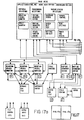
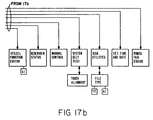
- Figure 8 shows the main menu of the system as it appears on the touchscreen, which corresponds to the bottom of a tree (shown in Figure 17) of various other more detailed menus.
- Each outlined block corresponds to an area on the touchscreen by which the series of menus in that tree is accessed. For example, touching the screen at the block labeled "PEPTIDE SEQ. EDITOR”, initiates another display, Figure 9, listing all of the amino acids, and allows the selection and display of the order of amino acids from N to C terminus appearing in the peptide to be synthesized by simply touching the block containing the name of the desired amino acid in the desired sequence.
- PEPTIDE CHEMISTRY EDITOR Touching the screen at the block labeled "PEPTIDE CHEMISTRY EDITOR", when the main menu is displayed brings up the PEPTIDE CHEMISTRY EDITOR menu, Figure 10, which allows the operator to create or edit either cycle specifications in a particular vessel or the run file specification. As an example, if it is elected to create or edit a new activator cycle, a CYCLE EDITOR menu corresponding to the activator vessel appears on the screen. (See Figure 11.) This menu enables the operator to change the order of the functions involved in each cycle of the activator, and similarly for menus corresponding to the other vessels.
- TIME a required primary time
- MIN TIME a time based on detector measurements
- ERP TIME an additional time added for particular sets of steps in the reaction vessel
- TIME has several purposes.
- TIME is the total time for the step.
- the primary time is the "time out” or maximum time allowed before continuing regardless of whether or not the appropriate transition was detected by the liquid sensor.
- the user when liquid detection is specified, the user must specify a minimum time, MIN TIME, before the appropriate transition (liquid to gas or gas to liquid) is to registered. It is important to note another effect of TIME when detection is specified.
- ERR MODE is used in the event that detection is specified and the specified transition is not seen before the primary time has elapsed, e.g. if a valve is blocked or a particular reservoir is empty. This mode can be used to trigger an alarm or, in some cases, to effect a non-disastrous termination of the synthesis.
- ADD TIME refers specifically to the reaction vessel only, and corresponds to the amount of time (in tenths of a second) to be added to each of the three previous fields as a function of amino acid number in the sequence of the peptide being synthesized. Since the occupied volume in the reaction vessel increases with each additional amino acid coupling, the step times in the reaction vessel also increase. For example, if the value 10 is entered into this field, one second (10/10ths) will be added to the primary time for the second amino acid to be coupled in the peptide sequence. For the third amino acid, the time would be increased by two seconds, and so forth.
- RUN FILE EDITOR in the PEPTIDE CHEMISTRY EDITOR is selected, displaying the RUN FILE EDITOR menu shown in Figure 12.
- the table displayed therein corresponds to what is called the static run file.
- This file designates three cycles (one each for the activator vessel, the concentrator vessel, and the reaction vessel), for each of twenty six amino acid possibilities, and allows independent adjustment of the concentrator temperature for each amino acid.
- the twenty six amino acid possibilities provided are comprised of the twenty standard amino acids, an additional four for specialized use as might be desired by the operator, and a BEGIN cycle and an END cycle to allow independent control of these points in the synthesis.
- This static run file is the result of specifying the chemistry for each cycle through the various CYCLE EDITORS which have alreadybeen described).
- all cycles designated by a particular run file must be resident on a disc currently installed in the system, since the RUN FILE EDITOR will only allow choices from a list of resident cycles.
- each of the three reaction vessels may synthesize from a different (or the same) run file, since, at the time a run is set up, the run file is specified for the particular vessel in the REACTION VESSEL MONITOR (which will be discussed later).
- the operator may create, edit, and store a number of run files on a single disc (up to 20). It should also be noted that although the system is designed to permit a different cycle for each amino acid possibility, it has been found in practice that not nearly that many cycles are needed to provide efficient operations.
- VESSEL FUNCTION EDITOR This menu is accessed from the main menu, and operates at the most basic level of the synthesizer. Itinvolves the individual instructions required to accomplish a particular function in a particular vessel. For example, if it is desired to change the definition of a function or add or delete functions which are to occur in the activator vessel, the FUNCTION EDITOR shown in Figure 13 corresponding to the activator vessel is called. Here, the entire set of functions for the activator can be reviewed and changed. As indicated earlier, a function is a named set of switches turned on simultaneously. These functions usually create a chemical flow path through the system.
- the function "DCC TO ACTIVATOR” may be defined as switches 114 (DCC delivery valve), 119 (pressurize DCC bottle), and 125 (open activator to waste). Also some functions describe mechanical or electrical actions only, such as “heater on”, (one switch).
- the system is organized into three types of functions: ON/OFF, TOGGLE ON, and TOGGLE OFF, specified as type 0, 1, and 2, respectively.
- An ON/OFF function turns switches on for a given step in a cycle only. At the end of that given step, all switches for that function are cleared (turned off) before the next function is activated.
- a TOGGLE ON function directs the machine to turn on certain switches and leave them on until a corresponding TOGGLE OFF function turns them off.
- TOGGLE ON functions are "Heater on” for the concentrator vessel, or VORTEX ON" for the reaction vessel.
- Calling the REACTION VESSEL MONITOR from the main menu presents the screen shown in Figure 14, which lets the operator set up and monitor the synthesis.
- Two response fields permit the operator to select between two modes of operation, a first mode which automatically controls the apparatus based on the input to the PEPTIDE SEQ. EDITOR and a set of preprogrammed cycles called the dynamic run file; and a second mode which operates based only on which cartridges (kinds of amino acids) are loaded into the autodelivery system and a set of preprogrammed cycles from a designated static run file. If the first mode is chosen, the computer initiates a question as to whether the operator wishes to change the dynamic run file.
- FIG. 15 a screen as shown in Figure 15 is displayed, corresponding to an editor for the dynamic run file.
- This file is generated initially internally when the operator enters the desired peptide sequence into the PEPTIDE SEQ. EDITOR. It is simply a table listing the sequence of amino acids in the order to be synthesized, with the designated cycles for each amino acid as has already been programmed from the designated static run file.
- This editor is designed so that the operator can alter the cycles used for particular amino acids in the sequence depending on where they are located in the peptide chain, so that the operator has position dependent control over the chemistry.
- the dynamic run file is not stored on the disc.
- a series of questions is then generated to ensure that the apparatus is properly set up to begin operations, e.g. checks are made as to whether the reaction vessel is loaded, and whether the autoloader has the desired number and order of amino acids. Following that series of inquiries, the final inquiry is whether to begin or to stop operations. Also as part of the function of the REACTION VESSEL MONITOR, the status of the reaction vessel is displayed, including the name of the activated amino acid that is currently undergoing reaction, the time that the synthesis of peptide was initiated, and the time when the synthesis was completed. In addition, the current coupling is displayed and the sequence of couplings already completed can be displayed and reviewed by scrolling back and forth on the screen.
- MACHINE/STATUS SELECTIONS include: RESERVOIR STATUS which relates to the fact that the apparatus monitors the volume used from each reservoir during each cycle, so that when a reservoir runs low an alarm is registered to inform the operator of the problem; INSTRUMENT CONFIG. which is used to display and set the configuration of the machine itself, e.g.
- SYSTEM SELF TEST which tests all of the electronic functions to the extent practicable
- CONTROL AND TEST which allows manual control of the apparatus to the extent that the operator can manipulate each valve and switch, one at a time, in order to facilitate debugging and to enable manual intervention of synthesis if necessary
- DISK UTILITIES which allows the operator to carry out customary disc functions necessary to the operation of a computer system, e.g. setting up files, purging files, and renaming files.
- Another characteristic of the apparatus which is controlled by the software is the simultaneity of operations in the reaction vessel, the concentrator vessel, and the activator vessel.
- an automated optimization scheme hereinafter called a cycle compiler, has been developed to provide maximum efficiency in the synthesis of each particular peptide given a particular chemistry.
- a cycle compiler an automated optimization scheme, hereinafter called a cycle compiler.
- these functions correspond to the beginning of a transfer, BOTA; the end of a transfer, EOTA. particular peptide, given a particular chemistry.
- the key functions include identifying when the vessel is ready to receive, RC; as well as the beginning of a transfer, BOTC; the end of a transfer, EOTC.
- these functions delineate when the vessel is ready to receive, RR.
- the next step then is to determine in which vessel operations should begin first, in order to optimize the process.
- These left side delays pertain to the waiting time allowed before preparing the particular vessel for the function that is to take place there, e.g. for the activator vessel, some waiting time may be allowed before transferring amino acid into the vessel and creating the symmetric anhydride, and for the reaction vessel, there may be some waiting time allowed before beginning the deprotection of the resin-bound peptide chain.
- the shortest delay i.e.
- T MA T EOTA - T BOTA + (T BOTC - T RC ), and T ML ⁇ MAX (T BOTA , T RC , T RX ), where T RX ⁇ T RR - T MA .
- T DLA T ML - T BOTA
- T DLC T ML - T RC
- T DLR T ML - T RX .
- T DRA T BOX - T DLA - T AT ;
- T DRC T BOX - T DLC - [T CT + (T EOTA - T BOTA )];
- T DRR T BOX - T DLR - [T RT + (T EOTC - T BOTC )];
- T BOX MAX [(T AT + T DLA ), (T CT + (T EOTA - T BOX ) + T DLC ), (T RT + (T EOTC - T BOTC ) + T DLR )];
- T AT , T CA , and T RT correspond to the total time for the activator cycle, concentrator cycle, and reaction vessel cycle, respectively.
- T DLA2 , T DLC2 , and T DLR2 are the left side delays of the second cycle (calculated using the same technique as for the left side delays in the first cycle).
- T WA2 , T WC2 , and T WR2 are the waiting times for the activator vessel, the concentrator vessel, and the reaction vessel, respectively, from the last step of the first cycle to the first step of the second cycle.
- T WA2 , T WC2 , and T WR2 must be zero, as was the case for left side delays in the first cycle.
- Figure 19 shows the results of the above calculation for a series of three cycles.
- FIG. 20 illustrate the relative advantage of the claimed apparatus for the synthesis of the decapeptide Acyl Carrier Protein (65-74).
- the uppermost line is a graphical representation of the individual cycle yields for each amino acid addition during the peptide chain assembly as performed on the apparatus of the invention. Except for glutamine (symbolized by Gln), all amino acid additions were accomplished by a fully automated sequence of single couplings: glutamine requires a special chemical protocol well known in the art that consists of double coupling with HOBT (hydroxybenzotriazole) activation. All other couplings were done with Boc-amino acid symmetric anhydrides.
- the lower line depicts results of the synthesis of the same peptide on a Beckman 990 Peptide Synthesizer using Boc-amino acid symmetric anhydrides pre-formed manually, off the instrument.
- the results demonstrate that fully automated synthesis was precluded by the need to manually preform the symmetric anhydrides, and that the manually preformed symmetric anhydrides were not optimally formed.
- Some peptide amino acid sequences demonstrate unique, sequence specific coupling problems where even second and third couplings, typically in DCM, fail to effect greater than 99% coupling yields, irrespective of the activated form of the amino acid (see W. S. Hancock, D. J. Prescott, P. R. Vagelos, and G. R. Marshall, J. Org. 38 (1973) 774).
- sequence dependent incomplete couplings performed in poor solvents such as DCM would be much improved if performed exclusively in more polar solvents such a DMF (see S. Meister, S. B. H. Kent, Peptides , Structure & Function , Proceedings of the 8th American Peptide Symposium , pps. (103-106).
- the Acyl Carrier Protein (65-74) decapeptide is such a known problem sequence and the excellent results achieved on the claimed apparatus by coupling with Boc-amino acid symmetric anhydrides in DMF demonstrate one of the chief advantages of the apparatus: optimal formation of the activated amino acid in DCM, but coupling of the activated amino acid in DMF. This automatically executed method affords a general solution to the synthesis of problem peptide sequences.
Landscapes
- Chemical & Material Sciences (AREA)
- Organic Chemistry (AREA)
- Medicinal Chemistry (AREA)
- Molecular Biology (AREA)
- Biochemistry (AREA)
- Biophysics (AREA)
- General Health & Medical Sciences (AREA)
- Genetics & Genomics (AREA)
- Health & Medical Sciences (AREA)
- Life Sciences & Earth Sciences (AREA)
- Proteomics, Peptides & Aminoacids (AREA)
- Analytical Chemistry (AREA)
- Chemical Kinetics & Catalysis (AREA)
- Peptides Or Proteins (AREA)
- Physical Or Chemical Processes And Apparatus (AREA)
- Organic Low-Molecular-Weight Compounds And Preparation Thereof (AREA)
Claims (21)
- Vorrichtung zur Herstellung von Peptiden durch Synthese aus der festen Phase heraus, aufweisend:
Aktivierungseinrichtungen zur Aufnahme geschützter Aminosäuren, welche ein übliches Aktivierungsgefäß (11), in welchem jede einzelne Aminosäure aktiviert wird, und Lösemittel-Kopplungsmedium-Substitutionseinrichtungen (33, 41) aufweisen;
ein Reaktionsgefäß (15) zur Aufnahme des Substrates in irgendeinem zweckmäßigen Lösemittel;
Übertragungseinrichtungen (Fig. 1B), die mit den Aktivierungseinrichtungen und dem Reaktionsgefäß verbunden sind, um in der Vorrichtung eingesetzte Materialien zu übertragen;
und mit der Übertragungseinrichtung verbundene Rechnereinrichtungen (Fig. 2), um die Übertragung von aufeinanderfolgenden Aliquots von Aminosäuren in einer vorgewählten Sequenz in die Aktivierungseinrichtungen hinein; um die Übertragung von entsprechenden folgenden Aliquots des Aktivierungsmediums in die Aktivierungseinrichtungen und die Übertragung von folgendem Aliquot von aktivierten Aminosäuren, die auf diese Art und Weise erzeugt worden sind, in der vorgewählten Sequenz in das Reaktionsgefäß hinein automatisch zu steuern, um auf diese Art und Weise dem Substrat einzeln aktivierte Aminosäuren in der vorgewählten Sequenz zuzuführen. - Vorrichtung nach Anspruch 1, gekennzeichnet durch Computersoftware, durch welche Temperaturen und Zyklusperioden für jede Aminosäure verändert werden können.
- Vorrichtung nach Anspruch 2, dadurch gekennzeichnet, daß das Reaktionsgefäß (15) einen Rührer (48) enthält, der mit einer Wirbeleinrichtung arbeitet, um Harz-Agglomeration während der Reaktion mit jeder der aktivierten Spezies der Aminosäure zu verhindern.
- Vorrichtung nach Anspruch 3, dadurch gekennzeichnet, daß das Reaktionsgefäß einen Behälter aufweist, der eine Rotationssymmetrieachse hat.
- Vorrichtung nach Anspruch 4, dadurch gekennzeichnet, daß der Rührer eine Rotationseinrichtung aufweist, die so angeordnet ist, daß das eine Ende des Behälters eine kreisförmige Bewegung um die Rotationssymmetrieachse ausübt, während das andere Ende im wesentlichen ortsfest gehaltert ist.
- Vorrichtung nach einem der Ansprüche 1 bis 4, dadurch gekennzeichnet, daß die Aktivierungseinrichtung ein Konzentratorgefäß (13) aufweist, um das Aktivatorlösungsmittel und jede der aktivierten Spezies der Aminosäure aufzunehmen, und zwar jede Aminosäure einzeln von dem Aktivierungsgefäß, und daß die Übertragungseinrichtungen so angeordnet sind, um das Aktivatorlösungsmedium aus dem Konzentratorgefäß durch ein Kupplungsmedium zu ersetzen.
- Vorrichtung nach einem der Ansprüche 1 bis 6, dadurch gekennzeichnet, daß die Übertragungseinrichtungen auch eine selbst ausgebende Einrichtung (Fig. 3) enthalten, die unter der Steuerung der Computereinrichtung die Aminosäuren jeweils einzeln, in der gewünschten Reihenfolge des Peptides an die Aktivierungseinrichtung abgeben,
die selbst ausgebende Einrichtung eine Einrichtung zum individuellen Weiterschalten der Behälter für die Aminosäuren in der gewünschten Reihenfolge des Peptides enthält, und
daß eine Extraktionseinrichtung (121, 123) vorgesehen ist, um die Inhalte der einzelnen Behälter einzeln zu extrahieren. - Vorrichtung nach Anspruch 7, dadurch gekennzeichnet, daß die Extraktionseinrichtung eine Nadeleinrichtung (121, 123) aufweist, um Lösemittel in jeden der Behälter abzugeben und um das Lösemittel zusammen mit der Aminosäure aus den Behältern herauszuziehen.
- Vorrichtung nach Anspruch 7 oder 8, dadurch gekennzeichnet, daß einzelne Behälter (105) in einer Weiterschalteinrichtung angeordnet sind und daß
jeder der Behälter mit einem Boden ausgebildet ist, der innen die Gestalt eines Troges hat. - Vorrichtung nach Anspruch 9, dadurch gekennzeichnet, daß die Behälter (145) ohne äußere Vorkehrungen aufrechtstehend ausgebildet sind.
- Vorrichtung nach Anspruch 6, dadurch gekennzeichnet, daß die Übertragungseinrichtungen eine erste Rohrleitung zwischen dem Aktivierungsgefäß und dem Konzentratorgefäß und einen ersten Ventilblock (23), der durch die Computereinrichtung gesteuert ist, um den Fluß von dem Aktivierungsgefäß in die erste Leitung zu steuern und einen zweiten Ventilblock (33) aufweisen, der durch die Computereinrichtung gesteuert ist, um den Fluß in das Konzentratorgefäß von der ersten Leitung her zu steuern.
- Vorrichtung nach Anspruch 11, dadurch gekennzeichnet, daß die Übertragungseinrichtungen auch eine zweite Rohrleitung zwischen dem Konzentratorgefäß und dem Reaktionsgefäß und einen dritten Ventilblock (45) aufweisen, der durch die Computereinrichtung gesteuert ist, um den Fluß in das Reaktionsgefäß hineinzusteuern, und wobei der zweite Ventilblock ebenfalls den Fluß von dem Konzentratorgefäß in die zweite Leitung hineinsteuert.
- Vorrichtung nach Anspruch 11 bis 12, gekennzeichnet durch eine Flüssigkeitsensoreinrichtung (27, 40, 48), um Übergänge zwischen Gasen und Flüssigkeiten, die in der Leitung strömen, festzustellen.
- Vorrichtung nach einen der Ansprüche 1 bis 13, gekennzeichnet durch einen Harzprobennehmer (59), der durch die Computereinrichtung gesteuert ist, um Materialien aus dem Reaktionsgefäß herauszuziehen.
- Vorrichtung nach einen der Ansprüche 1 bis 14, dadurch gekennzeichnet, daß die Computereinrichtung eine Menüeinrichtung zur Kategorisierung physikalischer und chemischer Operationen oder Vorgänge in der Vorrichtung aufweist, um die Steuerung über diese Vorgänge durch eine Bedienungsperson zu ermöglichen, wobei die Kategorisierung in einen Satz von Zyklen unterteilt ist und jeder Zyklus für einen kompletten Satz von Vorgängen in einem der Gefäße, dem Aktivierungsgefäß, dem Konzentratorgefäß und dem Reaktionsgefäß charakteristisch ist.
- Vorrichtung nach Anspruch 15, dadurch gekennzeichnet, daß die Computereinrichtung Speicher zur Speicherung eines Algorythmusses zur Berechnung der Tätigkeitszeitspannen für den ersten, den zweiten und den dritten Ventilblock aufweist, um die Produktion eines Polypeptides mit irgendeiner gegebenen speziellen Sequenz von Zyklen in jedem der Gefäße, dem Aktivierungsgefäß, dem Konzentratorgefäß und dem Reaktionsgefäß zu maximieren.
- Vorrichtung nach Anspruch 15, dadurch gekennzeichnet, daß die Computereinrichtung eine Einrichtung zur Berechnung der Operationszeiten und der Schaltzeiten zur Betätigung des ersten, zweiten und dritten Ventilblocks in Übereinstimmung mit den Arbeitszeiten aufweist.
- Vorrichtung nach Anspruch 14, dadurch gekennzeichnet, daß der Harz-Probennehmer aufweist:
ein Reservoir;
eine in dem Reservoir angeordnete Membrane zur Unterbrechung des Materialflusses oberhalb einer bestimmten Größe an der Stelle der Membrane in dem Reservoir;
eine erste Verbindungsleitung, die mit dem Reservoir an der einen Seite der Membrane verbunden ist;
ein erstes Ventil zur Steuerung des Flusses durch die Verbindungsrohrleitung;
eine zweite Verbindungsrohrleitung, die an das Reservoir an der Seite der ersten Verbindungsrohrleitung der Membrane angeschlossen ist;
ein zweites Ventil zur Steuerung des Flusses durch die zweite Verbindungsrohrleitung; und
eine dritte Verbindungsrohrleitung, die mit dem Reservoir an der gegenüberliegenden Seite der Membrane verbunden ist. - Vorrichtung nach Anspruch 13, dadurch gekennzeichnet, daß die Flüssigkeitssensoreinrichtung aufweist:
zwei im wesentlichen flache Substrate (217, 218), die aus einem nachgiebigen Material gebildet sind und in einer im wesentlichen gegenüberliegenden Lage relativ zueinander und in einem festen Abstand in der Nähe des ersten Endes gehaltert sind;
eine Halteeinrichtung (229), die am gegenüberliegenden Ende und zwischen den Substraten zur Halterung der Rohrleitung angeordnet ist, wobei die Dicke der Leitung und der Halteeinrichtung zusammen den festen Abstand überschreiten;
eine Belichtungseinrichtung (270), die durch die Halteeinrichtung gehaltert ist, um Strahlungsenergie von der einen Seite der Leitung her zur Verfügung zu stellen, und
einen Detektor (271), der durch die Halteeinrichtung an der der Belichtungseinrichtung gegenüberliegenden Seite der Leitung gehaltert ist, um die Strahlungsenergie aufzunehmen, die durch die Leitung von der Belichtungseinrichtung her übertragen worden ist, und um Veränderungen in der Intensität des durch die Leitung hindurchgegangenen Lichts festzustellen. - Vorrichtung nach Anspruch 9, dadurch gekennzeichnet, daß jeder der Behälter aufweist:
zwei im wesentlichen zueinander parallele Seitenteile;
zwei weitere Seitenteile, die einander gegenüberliegend symmetrisch angeordnet sind und mit den beiden im wesentlichen parallelen Seitenteilen verbunden sind, um eine Kastenform zu bilden;
ein Bodenteil, der mit den Seitenteilen verbunden ist und eine innere Konfiguration eines V-förmigen Troges aufweist, wobei die Längserstreckung des Troges senkrecht zu den parallelen Seitenteilen steht und der Bodenteil einen äußeren Abschnitt in der Mitte des Troges aufweist, welcher im wesentlichen flach ausgebildet ist;
einen Flansch (145), der mit dem Bodenteil verbunden ist und zwischen den parallelen Seiten angeordnet ist, orthogonal zur Längserstreckung des Troges steht und eine flache Oberfläche aufweist, die im wesentlichen gleich erstreckend mit der flachen Oberfläche des Mittelteils des Troges ausgebildet ist; und
einen Oberteil, der mit einer Trennwand ausgebildet und mit den Seitenteilen verbunden ist, um einen geschlossenen Raum zu bilden. - Vorrichtung nach Anspruch 7, dadurch gekennzeichnet, daß die selbstabgebende Einrichtung aufweist:
eine Spureinrichtung (101), um eine Anordnung einzelner Behälter (105) für Aminosäuren zu haltern und um die Bewegung der Kartuschen zu dirigieren;
eine Antriebseinrichtung, um die Anordnung der Kartuschen in einer Richtung längs der Spur zu bewegen;
eine Ejektoreinrichtung (113), die gegenüberliegend zur Antriebseinrichtung angeordnet ist und dem Antrieb entgegenwirkt, und um die Anordnung festzuhalten, wenn Aminosäuren aus einer Kartusche herausgenommen wird, und um eine Kartusche aus der Anordnung aus zugeben, wenn aus dieser Aminosäure extrahiert worden ist; und
eine Extraktionseinrichtung (121, 123), die in der Nähe der Spur angeordnet ist, um Aminosäure aus den Kartuschen zu extrahieren.
Applications Claiming Priority (2)
| Application Number | Priority Date | Filing Date | Title |
|---|---|---|---|
| US06/592,638 US4668476A (en) | 1984-03-23 | 1984-03-23 | Automated polypeptide synthesis apparatus |
| US592638 | 1984-03-23 |
Related Child Applications (1)
| Application Number | Title | Priority Date | Filing Date |
|---|---|---|---|
| EP92108583.3 Division-Into | 1985-03-13 |
Publications (3)
| Publication Number | Publication Date |
|---|---|
| EP0156588A2 EP0156588A2 (de) | 1985-10-02 |
| EP0156588A3 EP0156588A3 (en) | 1986-05-28 |
| EP0156588B1 true EP0156588B1 (de) | 1993-05-05 |
Family
ID=24371478
Family Applications (2)
| Application Number | Title | Priority Date | Filing Date |
|---|---|---|---|
| EP19920108583 Withdrawn EP0503683A1 (de) | 1984-03-23 | 1985-03-13 | Verfahren zur Herstellung von Peptiden mittels Festphasensynthese |
| EP85301729A Expired - Lifetime EP0156588B1 (de) | 1984-03-23 | 1985-03-13 | Automatisierter Polypeptidsyntheseapparat |
Family Applications Before (1)
| Application Number | Title | Priority Date | Filing Date |
|---|---|---|---|
| EP19920108583 Withdrawn EP0503683A1 (de) | 1984-03-23 | 1985-03-13 | Verfahren zur Herstellung von Peptiden mittels Festphasensynthese |
Country Status (4)
| Country | Link |
|---|---|
| US (2) | US4668476A (de) |
| EP (2) | EP0503683A1 (de) |
| JP (1) | JPS60237097A (de) |
| DE (1) | DE3587315T2 (de) |
Families Citing this family (108)
| Publication number | Priority date | Publication date | Assignee | Title |
|---|---|---|---|---|
| US5273715A (en) * | 1984-03-23 | 1993-12-28 | Applied Biosystems, Inc. | Automated system for providing a sequence of chemicals to a reaction process |
| JPH0640054B2 (ja) * | 1985-09-20 | 1994-05-25 | 株式会社千代田製作所 | 電子顕微鏡標本作成用包埋装置 |
| US4908773A (en) * | 1987-04-06 | 1990-03-13 | Genex Corporation | Computer designed stabilized proteins and method for producing same |
| US5552528A (en) | 1986-03-03 | 1996-09-03 | Rhone-Poulenc Rorer Pharmaceuticals Inc. | Bovine b-endothelial cell growth factor |
| US5827826A (en) | 1986-03-03 | 1998-10-27 | Rhone-Poulenc Rorer Pharmaceuticals Inc. | Compositions of human endothelial cell growth factor |
| US4889812A (en) * | 1986-05-12 | 1989-12-26 | C. D. Medical, Inc. | Bioreactor apparatus |
| US5039488A (en) * | 1986-06-06 | 1991-08-13 | Genentech, Inc. | Devices for amino acid sequence determination |
| US4852017A (en) * | 1987-06-19 | 1989-07-25 | Applied Biosystems, Inc. | Determination of peptide sequences |
| IE64511B1 (en) * | 1988-03-11 | 1995-08-09 | Takeda Chemical Industries Ltd | Automated synthesizing apparatus |
| US5239484A (en) * | 1988-03-31 | 1993-08-24 | Takeda Chemical Industries, Ltd. | Automatic synthesis apparatus |
| JP2708456B2 (ja) * | 1988-03-31 | 1998-02-04 | 武田薬品工業株式会社 | 自動合成装置 |
| US5147608A (en) * | 1988-04-29 | 1992-09-15 | Millipore Corporation | Apparatus and process for performing repetitive chemical processing |
| DK492788D0 (da) * | 1988-09-02 | 1988-09-05 | Morten Meldal | Peptidsynteseapparat |
| US5053454A (en) * | 1989-02-15 | 1991-10-01 | Sri International | Multiple polymer synthesizer |
| ES2098261T3 (es) * | 1989-02-21 | 1997-05-01 | Univ Washington | Formas modificadas de hormonas reproductoras. |
| JP3039802B2 (ja) | 1989-07-06 | 2000-05-08 | ザ リージェンツ オブザ ユニバーシティ オブ カリフォルニア | 繊維芽細胞成長因子のための受容体 |
| US5545522A (en) | 1989-09-22 | 1996-08-13 | Van Gelder; Russell N. | Process for amplifying a target polynucleotide sequence using a single primer-promoter complex |
| US7049102B1 (en) | 1989-09-22 | 2006-05-23 | Board Of Trustees Of Leland Stanford University | Multi-gene expression profile |
| CZ280777B6 (cs) * | 1990-02-02 | 1996-04-17 | Ústav Organické Chemie A Biochemie Avčr | Mnohonásobná automatizovaná syntéza peptidů na planárních nosičích |
| FR2664602B1 (fr) * | 1990-07-13 | 1993-08-20 | Centre Nat Rech Scient | Automate de synthese simultanee de plusieurs peptides identiques ou differents en phase solide et procede automatique de synthese mis en oeuvre par ledit automate. |
| DE69132905T2 (de) * | 1990-12-06 | 2002-08-01 | Affymetrix, Inc. (N.D.Ges.D.Staates Delaware) | Detektion von Nukleinsäuresequenzen |
| US5243540A (en) * | 1991-04-03 | 1993-09-07 | The United States Of America As Represented By The Secretary Of The Army | Computer-driven amino acid indexer for peptide synthesis |
| US5499193A (en) * | 1991-04-17 | 1996-03-12 | Takeda Chemical Industries, Ltd. | Automated synthesis apparatus and method of controlling the apparatus |
| WO1992021079A1 (en) * | 1991-05-24 | 1992-11-26 | The President And Fellows Of Harvard College | Parallel sequential reactor |
| WO1993000625A1 (en) * | 1991-06-21 | 1993-01-07 | Sloan-Kettering Institute For Cancer Research | Computer-controlled, module type, multipurpose synthesizer |
| US5449754A (en) * | 1991-08-07 | 1995-09-12 | H & N Instruments, Inc. | Generation of combinatorial libraries |
| EP0541340B1 (de) * | 1991-11-05 | 1997-07-16 | The Perkin-Elmer Corporation | Vorrichtung und Verfahren zur Herstellung von Biopolymeren |
| US5651943A (en) * | 1991-11-19 | 1997-07-29 | Arizona Board Of Regents, On Behalf Of The University Of Arizona | Apparatus and method for random polymer synthesis |
| DE69233501T2 (de) * | 1991-11-22 | 2006-02-23 | Affymetrix, Inc. (n.d.Ges.d.Staates Delaware), Santa Clara | Kombinatorische Strategien für die Polymersynthese |
| US6943034B1 (en) * | 1991-11-22 | 2005-09-13 | Affymetrix, Inc. | Combinatorial strategies for polymer synthesis |
| US6849462B1 (en) | 1991-11-22 | 2005-02-01 | Affymetrix, Inc. | Combinatorial strategies for polymer synthesis |
| US5384261A (en) * | 1991-11-22 | 1995-01-24 | Affymax Technologies N.V. | Very large scale immobilized polymer synthesis using mechanically directed flow paths |
| US5240680A (en) * | 1991-12-19 | 1993-08-31 | Chiron Corporation | Automated apparatus for use in peptide synthesis |
| JPH0734910Y2 (ja) * | 1992-01-29 | 1995-08-09 | 株式会社島津製作所 | 固相法ペプチド合成器 |
| JPH08501489A (ja) * | 1992-07-06 | 1996-02-20 | ベックマン インスツルメンツ インコーポレーテッド | オンラインプロセスの流れおよび反応のモニタ |
| US5203368A (en) * | 1992-07-29 | 1993-04-20 | Protein Technologies Inc. | Matrix of valves |
| US5448499A (en) * | 1992-08-24 | 1995-09-05 | Olin Corporation | Mispour-misfill prevention apparatus and process |
| JPH06128286A (ja) * | 1992-10-13 | 1994-05-10 | Shimadzu Corp | 自動ペプチド合成装置 |
| US5380495A (en) * | 1993-08-27 | 1995-01-10 | Chang; Heng-Wei | Solid phase peptide synthesizer |
| US6737515B2 (en) | 1993-11-19 | 2004-05-18 | Washington University | Follicle stimulating hormone-glycosylation analogs |
| US5580523A (en) * | 1994-04-01 | 1996-12-03 | Bard; Allen J. | Integrated chemical synthesizers |
| US20050042149A1 (en) * | 1994-04-01 | 2005-02-24 | Integrated Chemical Synthesizers, Inc. | Nanoscale chemical synthesis |
| US7625697B2 (en) | 1994-06-17 | 2009-12-01 | The Board Of Trustees Of The Leland Stanford Junior University | Methods for constructing subarrays and subarrays made thereby |
| US7323298B1 (en) | 1994-06-17 | 2008-01-29 | The Board Of Trustees Of The Leland Stanford Junior University | Microarray for determining the relative abundances of polynuceotide sequences |
| US6558633B1 (en) | 1994-09-21 | 2003-05-06 | Isis Pharmaceuticals, Inc. | Chemical reaction apparatus and methods |
| EP0803063A4 (de) * | 1995-01-11 | 1998-04-29 | Panlabs Inc | Verfahren zur erzeugung von grossen katalogisierten chemischen bibliotheken |
| US5670114A (en) * | 1995-03-08 | 1997-09-23 | Hitachi, Ltd. | Apparatus of handling reagent for suppressing decrease in effect of reagent |
| US6329139B1 (en) | 1995-04-25 | 2001-12-11 | Discovery Partners International | Automated sorting system for matrices with memory |
| US6017496A (en) * | 1995-06-07 | 2000-01-25 | Irori | Matrices with memories and uses thereof |
| US5744102A (en) * | 1996-01-30 | 1998-04-28 | Chugai Biopharmaceuticals, Inc. | Solid phase synthesizer |
| GB9603945D0 (en) * | 1996-02-24 | 1996-04-24 | Univ Dundee | A microreactor |
| US5746982A (en) * | 1996-02-29 | 1998-05-05 | Advanced Chemtech, Inc. | Apparatus for automated synthesis of chemical compounds |
| DE19612650C1 (de) * | 1996-04-02 | 1997-07-31 | Evotec Biosystems Gmbh | Verfahren zur Fluoreszenzmarkierung von Molekülen |
| US5851413A (en) * | 1996-06-19 | 1998-12-22 | Micrion Corporation | Gas delivery systems for particle beam processing |
| US5798035A (en) | 1996-10-03 | 1998-08-25 | Pharmacopeia, Inc. | High throughput solid phase chemical synthesis utilizing thin cylindrical reaction vessels useable for biological assay |
| US6136274A (en) * | 1996-10-07 | 2000-10-24 | Irori | Matrices with memories in automated drug discovery and units therefor |
| WO1998049187A1 (en) * | 1997-04-28 | 1998-11-05 | Chiron Corporation | Apparatus for synthesis of oligomers, especially peptoids, with reagent recycling |
| GB9716454D0 (en) * | 1997-08-05 | 1997-10-08 | Univ St Andrews | Polymer |
| EP1009757A1 (de) | 1997-09-04 | 2000-06-21 | Gryphon Sciences | Modulare peptid-bibliotheken und verfaahren zu deren herstellung |
| US6809075B1 (en) | 2000-05-30 | 2004-10-26 | Connective Tissue Imagineering Llc | Elastin peptide analogs and uses of same incombination with skin enhancing agents |
| US6962904B1 (en) | 1998-03-13 | 2005-11-08 | Connective Tissue Imagineering | Elastin peptide analogs and uses thereof |
| US20030228597A1 (en) * | 1998-04-13 | 2003-12-11 | Cowsert Lex M. | Identification of genetic targets for modulation by oligonucleotides and generation of oligonucleotides for gene modulation |
| US7321828B2 (en) * | 1998-04-13 | 2008-01-22 | Isis Pharmaceuticals, Inc. | System of components for preparing oligonucleotides |
| US6270730B1 (en) | 1998-06-16 | 2001-08-07 | Northwest Engineering Inc. | Multi-well rotary synthesizer |
| US6271042B1 (en) * | 1998-08-26 | 2001-08-07 | Alpha Innotech Corporation | Biochip detection system |
| US6777389B1 (en) | 1998-11-19 | 2004-08-17 | Connective Tissue Imagineering Llc | Cosmetic or dermatological use of 7-hydroxylated steroids in combination with elastin derived peptides |
| US6264891B1 (en) * | 1998-12-22 | 2001-07-24 | Eos Biotechnology, Inc. | Apparatus and method for concurrent chemical synthesis |
| US6794362B1 (en) * | 2000-05-30 | 2004-09-21 | Connective Tissue Imagineering Llc | Asparagine containing elastin peptide analogs |
| US6592827B1 (en) * | 2000-10-24 | 2003-07-15 | Univation Technologies Llc | Sampling system for fluidized bed gas phase polymerization reaction systems |
| US6859755B2 (en) | 2001-05-14 | 2005-02-22 | Rosemount Inc. | Diagnostics for industrial process control and measurement systems |
| US20050165558A1 (en) * | 2002-02-26 | 2005-07-28 | Becker Robert G. | Sequence detection system calculator |
| US7304128B2 (en) | 2002-06-04 | 2007-12-04 | E.I. Du Pont De Nemours And Company | Carbon nanotube binding peptides |
| US7396913B2 (en) * | 2002-10-14 | 2008-07-08 | Abbott Laboratories | Erythropoietin receptor binding antibodies |
| JP4583701B2 (ja) * | 2002-10-18 | 2010-11-17 | 株式会社ケムジェネシス | 液相系自動有機合成装置 |
| US20040136873A1 (en) * | 2003-01-09 | 2004-07-15 | Argonaut Technologies, Inc. | Modular reactor system |
| US7393920B2 (en) * | 2003-06-23 | 2008-07-01 | Cem Corporation | Microwave-assisted peptide synthesis |
| US7674881B2 (en) * | 2005-10-07 | 2010-03-09 | The University Of Chicago | Convergent synthesis of proteins by kinetically controlled ligation |
| US8097419B2 (en) | 2006-09-12 | 2012-01-17 | Longhorn Vaccines & Diagnostics Llc | Compositions and method for rapid, real-time detection of influenza A virus (H1N1) swine 2009 |
| US8652782B2 (en) | 2006-09-12 | 2014-02-18 | Longhorn Vaccines & Diagnostics, Llc | Compositions and methods for detecting, identifying and quantitating mycobacterial-specific nucleic acids |
| US9481912B2 (en) | 2006-09-12 | 2016-11-01 | Longhorn Vaccines And Diagnostics, Llc | Compositions and methods for detecting and identifying nucleic acid sequences in biological samples |
| US8080645B2 (en) | 2007-10-01 | 2011-12-20 | Longhorn Vaccines & Diagnostics Llc | Biological specimen collection/transport compositions and methods |
| US9683256B2 (en) | 2007-10-01 | 2017-06-20 | Longhorn Vaccines And Diagnostics, Llc | Biological specimen collection and transport system |
| US11041215B2 (en) | 2007-08-24 | 2021-06-22 | Longhorn Vaccines And Diagnostics, Llc | PCR ready compositions and methods for detecting and identifying nucleic acid sequences |
| AU2008293504B2 (en) | 2007-08-27 | 2012-04-12 | Longhorn Vaccines & Diagnostics, Llc | Immunogenic compositions and methods |
| US10004799B2 (en) | 2007-08-27 | 2018-06-26 | Longhorn Vaccines And Diagnostics, Llc | Composite antigenic sequences and vaccines |
| CA2861667C (en) | 2007-10-01 | 2017-06-13 | Longhorn Vaccines And Diagnostics, Llc | Biological specimen collection and transport system and methods of use |
| US11041216B2 (en) | 2007-10-01 | 2021-06-22 | Longhorn Vaccines And Diagnostics, Llc | Compositions and methods for detecting and quantifying nucleic acid sequences in blood samples |
| US8934994B1 (en) | 2008-07-30 | 2015-01-13 | Rusty S. Lee | Method and apparatus for automated fabrication |
| WO2013112916A1 (en) | 2012-01-26 | 2013-08-01 | Longhorn Vaccines And Diagnostics, Llc | Composite antigenic sequences and vaccines |
| JP6118593B2 (ja) * | 2013-03-12 | 2017-04-19 | 日立造船株式会社 | 両端開閉自在な耐圧反応器 |
| US9695214B2 (en) | 2013-03-15 | 2017-07-04 | Massachusetts Institute Of Technology | Solid phase peptide synthesis processes and associated systems |
| US9169287B2 (en) * | 2013-03-15 | 2015-10-27 | Massachusetts Institute Of Technology | Solid phase peptide synthesis processes and associated systems |
| US9069358B2 (en) | 2013-06-24 | 2015-06-30 | Biolytic Lab Performance, Inc. | System for controlling and optimizing reactions in solid phase synthesis of small molecules |
| WO2016183292A1 (en) | 2015-05-14 | 2016-11-17 | Longhorn Vaccines And Diagnostics, Llc | Rapid methods for the extraction of nucleic acids from biological samples |
| JP7054922B2 (ja) * | 2015-09-17 | 2022-04-15 | マサチューセッツ インスティテュート オブ テクノロジー | 固相ペプチド合成方法および関連するシステム |
| JP2018530543A (ja) | 2015-09-17 | 2018-10-18 | マサチューセッツ インスティテュート オブ テクノロジー | 固相ペプチド合成のための方法およびシステム |
| JP2019034290A (ja) * | 2017-08-21 | 2019-03-07 | 東レエンジニアリング株式会社 | 合成装置 |
| WO2019175867A1 (en) | 2018-03-13 | 2019-09-19 | Yissum Research Development Company Of The Hebrew University Of Jerusalem Ltd. | High shear solid phase synthesis |
| CN108286076B (zh) * | 2018-04-17 | 2024-09-20 | 中南大学 | 一种生物芯片原位制备系统及其应用方法 |
| CN108676056A (zh) * | 2018-06-19 | 2018-10-19 | 南京肽业生物科技有限公司 | 多肽反应合成单元 |
| EP3821974A1 (de) * | 2019-11-13 | 2021-05-19 | Bachem AG | Vorrichtung zur iterativen polymersynthese |
| JP2021094533A (ja) * | 2019-12-18 | 2021-06-24 | 東レエンジニアリング株式会社 | 合成装置及び合成方法 |
| US12485166B2 (en) | 2020-02-06 | 2025-12-02 | Longhorn Vaccines And Diagnostics, Llc | Vaccines for the treatment and prevention of zoonotic infections |
| SE548085C2 (en) | 2020-03-17 | 2026-02-27 | Peptisystems Ab | Peptide synthesis comprising pre-activation and recirculation of amino acids |
| KR20230091978A (ko) | 2020-10-20 | 2023-06-23 | 롱혼 백신즈 앤드 다이어그나스틱스, 엘엘씨 | 면역원성 항원 |
| US11571677B2 (en) | 2020-10-28 | 2023-02-07 | CSBio Instrumentation Co. | Peptide synthesis instrumentation |
| US20240287128A1 (en) | 2020-11-17 | 2024-08-29 | Yissum Research Development Company Of The Hebrew University Of Jerusalem Ltd. | Extremely fast solid phase synthesis |
| KR20240095247A (ko) * | 2021-10-18 | 2024-06-25 | 폴리펩티드 레브러토리즈 홀딩 (피피엘) 에이비 | 간헐적 삼출 세척 |
Family Cites Families (30)
| Publication number | Priority date | Publication date | Assignee | Title |
|---|---|---|---|---|
| US3356763A (en) * | 1962-04-09 | 1967-12-05 | Phillips Petroleum Co | Continuous process for producing block copolymers of dienes and vinyl aromatic hydrocarbons |
| US3244485A (en) * | 1962-07-17 | 1966-04-05 | Monsanto Co | Apparatus for preparing polycarbonamides |
| US3513145A (en) * | 1966-02-25 | 1970-05-19 | Crawford & Russell Inc | Continuous mass polymerization processes |
| US3557077A (en) * | 1967-09-18 | 1971-01-19 | Kay Brunfeldt | Reactions system |
| US3531258A (en) * | 1967-11-16 | 1970-09-29 | Us Health Education & Welfare | Apparatus for the automated synthesis of peptides |
| JPS4820995B1 (de) * | 1968-07-08 | 1973-06-25 | ||
| US3846399A (en) * | 1969-04-10 | 1974-11-05 | Merck & Co Inc | Process for controlled stepwise synthesis of polypeptides |
| US3645698A (en) * | 1969-10-06 | 1972-02-29 | Beckman Instruments Inc | Sampling apparatus |
| US3715190A (en) * | 1971-09-23 | 1973-02-06 | Univ Sherbrooke | System for the solid-phase peptide synthesis |
| GB1474524A (de) * | 1973-07-06 | 1977-05-25 | ||
| US3951741A (en) * | 1973-07-10 | 1976-04-20 | Peter Pfaender | Process and apparatus for the synthesis of peptides by use of n-carboxyanhydrides |
| DE2416941A1 (de) * | 1974-04-08 | 1975-10-09 | Helmut Pratzel | Verfahren zur synthese von peptiden nach der n-carboxyanhydrid-methode |
| US3944538A (en) * | 1973-10-02 | 1976-03-16 | Miklos Bodanszky | Process and apparatus for the synthesis of peptides not linked to polymers |
| DE2413703C3 (de) * | 1974-03-21 | 1979-01-04 | Max-Planck-Gesellschaft Zur Foerderung Der Wissenschaften E.V., 3400 Goettingen | Ventilanordnung für die Zuführung flüssiger oder gasförmiger Substanzen zu einem Verarbeitungsgefäß |
| US4065412A (en) * | 1976-05-07 | 1977-12-27 | Durrum Instrument Corporation | Peptide or protein sequencing method and apparatus |
| US4192798A (en) * | 1978-11-20 | 1980-03-11 | Bioresearch, Inc. | Rapid, large scale, automatable high pressure peptide synthesis |
| US4285858A (en) * | 1979-10-30 | 1981-08-25 | Mt. Sinai School Of Medicine Of The City University Of N.Y. | Vasopressin analogs |
| US4458066A (en) * | 1980-02-29 | 1984-07-03 | University Patents, Inc. | Process for preparing polynucleotides |
| IL62834A0 (en) * | 1980-05-14 | 1981-07-31 | Ens Bio Logicals Inc | Polynucleotide synthesis |
| FR2485003A1 (fr) * | 1980-06-23 | 1981-12-24 | Clin Midy | Appareillage automatise utilisable pour la synthese des peptides en phase solide |
| GB2084899B (en) * | 1980-09-23 | 1985-05-30 | California Inst Of Techn | Apparatus and method for the sequential performance of chemical processes |
| US4353989A (en) * | 1981-01-19 | 1982-10-12 | Ens Bio Logicals Inc. | Chemical synthesis apparatus for preparation of polynucleotides |
| US4362699A (en) * | 1981-03-10 | 1982-12-07 | Bio Research, Inc. | Apparatus for high pressure peptide synthesis |
| WO1982003077A1 (en) * | 1981-03-10 | 1982-09-16 | Inc Bioresearch | High performance peptide synthesis |
| US4492787A (en) * | 1981-09-18 | 1985-01-08 | Mitsubishi Chemical Industries Limited | Process for continuously producing propylene-ethylene block copolymer |
| JPS58194896A (ja) * | 1982-05-10 | 1983-11-12 | Shimadzu Corp | Dna等合成装置 |
| IL66094A0 (en) * | 1982-06-22 | 1982-09-30 | Yeda Res & Dev | Synthesis with multipolymer systems |
| IT1190891B (it) * | 1982-06-24 | 1988-02-24 | Anic Spa | Metodo per la sintesi in fase solida di polipeptidi retroinvertiti |
| US4483864A (en) * | 1983-02-04 | 1984-11-20 | University Of Iowa Research Foundation | Non-classical topical treatment for glaucoma |
| US4483964A (en) * | 1983-06-20 | 1984-11-20 | Chiron Corporation | Reactor system and method for polynucleotide synthesis |
-
1984
- 1984-03-23 US US06/592,638 patent/US4668476A/en not_active Expired - Lifetime
-
1985
- 1985-03-13 DE DE85301729T patent/DE3587315T2/de not_active Expired - Lifetime
- 1985-03-13 EP EP19920108583 patent/EP0503683A1/de not_active Withdrawn
- 1985-03-13 EP EP85301729A patent/EP0156588B1/de not_active Expired - Lifetime
- 1985-03-22 JP JP60055773A patent/JPS60237097A/ja active Granted
-
1987
- 1987-05-22 US US07/053,324 patent/US4816513A/en not_active Expired - Lifetime
Non-Patent Citations (1)
| Title |
|---|
| Ullmann's Encyklopädie der technischen Chemie, 4 Auflage Vol. 19, 1980, pages 542-552 * |
Also Published As
| Publication number | Publication date |
|---|---|
| DE3587315D1 (en) | 1993-06-09 |
| DE3587315T2 (de) | 1993-12-09 |
| EP0156588A2 (de) | 1985-10-02 |
| EP0156588A3 (en) | 1986-05-28 |
| US4816513A (en) | 1989-03-28 |
| US4668476A (en) | 1987-05-26 |
| JPS60237097A (ja) | 1985-11-25 |
| EP0503683A1 (de) | 1992-09-16 |
| JPH0469640B2 (de) | 1992-11-06 |
Similar Documents
| Publication | Publication Date | Title |
|---|---|---|
| EP0156588B1 (de) | Automatisierter Polypeptidsyntheseapparat | |
| US5186898A (en) | Automated polypeptide synthesis apparatus | |
| US5273715A (en) | Automated system for providing a sequence of chemicals to a reaction process | |
| AU687670B2 (en) | Apparatus and method for multiple synthesis of organic compounds on polymer support | |
| US4748002A (en) | Semi-automatic, solid-phase peptide multi-synthesizer and process for the production of synthetic peptides by the use of the multi-synthesizer | |
| EP0593460B1 (de) | Verfahren und vorrichtung zur biopolymersynthese | |
| EP0529504B1 (de) | Vorrichtung zur gleichzeitigen Herstellung von verschiedenen Peptiden | |
| JP4727769B2 (ja) | 試薬再循環を用いてオリゴマー、特に、ペプトイドを合成するための装置 | |
| WO1997012680A9 (en) | Matrices with memories, sensors with memories and uses thereof | |
| WO1998040159A2 (en) | Apparatus and method for combinatorial chemistry synthesis | |
| WO1990002605A1 (en) | An apparatus and a method for the synthesis of peptides | |
| US5316954A (en) | Methods and apparatus for processing liquids | |
| US5466608A (en) | Process and apparatus for heterogeneous phase synthesis of macromolecules such as peptides, polynucloetides or oligosaccharides | |
| US4153416A (en) | Process and apparatus for pulse labelling protein material in the Edman degradation process | |
| JPH03505004A (ja) | 化学反応処理を連続して行う装置及びその方法 | |
| WO2000012994A1 (en) | Apparatus for rapid protein and polypeptide sequence analysis | |
| JPS61205298A (ja) | 自動化ポリペプチド合成装置 | |
| JP2616370B2 (ja) | 多種品目同時化学反応装置 | |
| US20200384435A1 (en) | Device for parallel oligomer synthesis, method of parallel oligomer synthesis and use thereof | |
| JP3528352B2 (ja) | アミノ酸配列分析装置 | |
| EP0608779A1 (de) | Vorrichtung für Peptidsynthese | |
| Cammish et al. | phase peptide synthesis | |
| EP0934113B1 (de) | Umkehrfiltrationsvorrichtung sowie anwendungsverfahren | |
| Antonenko et al. | Combinatorial chemistry | |
| Atherton | Current chemical strategies in peptide synthesis |
Legal Events
| Date | Code | Title | Description |
|---|---|---|---|
| PUAI | Public reference made under article 153(3) epc to a published international application that has entered the european phase |
Free format text: ORIGINAL CODE: 0009012 |
|
| AK | Designated contracting states |
Designated state(s): DE FR GB SE |
|
| RIN1 | Information on inventor provided before grant (corrected) |
Inventor name: NORDMAN, ERIC SCOTT Inventor name: RAMSTAD, PAUL OLIVER Inventor name: MARRIOTT, MARK P. Inventor name: KENT, STEPHEN B.H. Inventor name: HUNKAPILLER, MICHAEL W. Inventor name: GEISER, TIMOTHY G. Inventor name: BRIDGHAM, JOHN |
|
| PUAL | Search report despatched |
Free format text: ORIGINAL CODE: 0009013 |
|
| AK | Designated contracting states |
Kind code of ref document: A3 Designated state(s): DE FR GB SE |
|
| 17P | Request for examination filed |
Effective date: 19861117 |
|
| 17Q | First examination report despatched |
Effective date: 19871216 |
|
| GRAA | (expected) grant |
Free format text: ORIGINAL CODE: 0009210 |
|
| XX | Miscellaneous (additional remarks) |
Free format text: 921120 |
|
| AK | Designated contracting states |
Kind code of ref document: B1 Designated state(s): DE FR GB SE |
|
| REF | Corresponds to: |
Ref document number: 3587315 Country of ref document: DE Date of ref document: 19930609 |
|
| ET | Fr: translation filed | ||
| PLBE | No opposition filed within time limit |
Free format text: ORIGINAL CODE: 0009261 |
|
| STAA | Information on the status of an ep patent application or granted ep patent |
Free format text: STATUS: NO OPPOSITION FILED WITHIN TIME LIMIT |
|
| 26N | No opposition filed | ||
| EAL | Se: european patent in force in sweden |
Ref document number: 85301729.1 |
|
| REG | Reference to a national code |
Ref country code: GB Ref legal event code: 732E |
|
| REG | Reference to a national code |
Ref country code: FR Ref legal event code: TP |
|
| REG | Reference to a national code |
Ref country code: GB Ref legal event code: IF02 |
|
| PGFP | Annual fee paid to national office [announced via postgrant information from national office to epo] |
Ref country code: GB Payment date: 20040310 Year of fee payment: 20 |
|
| PGFP | Annual fee paid to national office [announced via postgrant information from national office to epo] |
Ref country code: FR Payment date: 20040318 Year of fee payment: 20 |
|
| PGFP | Annual fee paid to national office [announced via postgrant information from national office to epo] |
Ref country code: SE Payment date: 20040319 Year of fee payment: 20 |
|
| PGFP | Annual fee paid to national office [announced via postgrant information from national office to epo] |
Ref country code: DE Payment date: 20040430 Year of fee payment: 20 |
|
| PG25 | Lapsed in a contracting state [announced via postgrant information from national office to epo] |
Ref country code: GB Free format text: LAPSE BECAUSE OF EXPIRATION OF PROTECTION Effective date: 20050312 |
|
| REG | Reference to a national code |
Ref country code: GB Ref legal event code: PE20 |
|
| EUG | Se: european patent has lapsed |