EP0159526A1 - Appareil pour la coupe de matière plate - Google Patents
Appareil pour la coupe de matière plate Download PDFInfo
- Publication number
- EP0159526A1 EP0159526A1 EP85103064A EP85103064A EP0159526A1 EP 0159526 A1 EP0159526 A1 EP 0159526A1 EP 85103064 A EP85103064 A EP 85103064A EP 85103064 A EP85103064 A EP 85103064A EP 0159526 A1 EP0159526 A1 EP 0159526A1
- Authority
- EP
- European Patent Office
- Prior art keywords
- support
- pivot axis
- carriage
- cutting machine
- column
- Prior art date
- Legal status (The legal status is an assumption and is not a legal conclusion. Google has not performed a legal analysis and makes no representation as to the accuracy of the status listed.)
- Granted
Links
Images


Classifications
-
- B—PERFORMING OPERATIONS; TRANSPORTING
- B26—HAND CUTTING TOOLS; CUTTING; SEVERING
- B26D—CUTTING; DETAILS COMMON TO MACHINES FOR PERFORATING, PUNCHING, CUTTING-OUT, STAMPING-OUT OR SEVERING
- B26D5/00—Arrangements for operating and controlling machines or devices for cutting, cutting-out, stamping-out, punching, perforating, or severing by means other than cutting
- B26D5/02—Means for moving the cutting member into its operative position for cutting
-
- B—PERFORMING OPERATIONS; TRANSPORTING
- B26—HAND CUTTING TOOLS; CUTTING; SEVERING
- B26F—PERFORATING; PUNCHING; CUTTING-OUT; STAMPING-OUT; SEVERING BY MEANS OTHER THAN CUTTING
- B26F1/00—Perforating; Punching; Cutting-out; Stamping-out; Apparatus therefor
- B26F1/38—Cutting-out; Stamping-out
- B26F1/3806—Cutting-out; Stamping-out wherein relative movements of tool head and work during cutting have a component tangential to the work surface
- B26F1/3813—Cutting-out; Stamping-out wherein relative movements of tool head and work during cutting have a component tangential to the work surface wherein the tool head is moved in a plane parallel to the work in a coordinate system fixed with respect to the work
-
- Y—GENERAL TAGGING OF NEW TECHNOLOGICAL DEVELOPMENTS; GENERAL TAGGING OF CROSS-SECTIONAL TECHNOLOGIES SPANNING OVER SEVERAL SECTIONS OF THE IPC; TECHNICAL SUBJECTS COVERED BY FORMER USPC CROSS-REFERENCE ART COLLECTIONS [XRACs] AND DIGESTS
- Y10—TECHNICAL SUBJECTS COVERED BY FORMER USPC
- Y10T—TECHNICAL SUBJECTS COVERED BY FORMER US CLASSIFICATION
- Y10T83/00—Cutting
- Y10T83/667—Tool carrier or guide affixed to work during cutting
-
- Y—GENERAL TAGGING OF NEW TECHNOLOGICAL DEVELOPMENTS; GENERAL TAGGING OF CROSS-SECTIONAL TECHNOLOGIES SPANNING OVER SEVERAL SECTIONS OF THE IPC; TECHNICAL SUBJECTS COVERED BY FORMER USPC CROSS-REFERENCE ART COLLECTIONS [XRACs] AND DIGESTS
- Y10—TECHNICAL SUBJECTS COVERED BY FORMER USPC
- Y10T—TECHNICAL SUBJECTS COVERED BY FORMER US CLASSIFICATION
- Y10T83/00—Cutting
- Y10T83/687—By tool reciprocable along elongated edge
- Y10T83/6905—With tool in-feed
- Y10T83/693—Of rectilinearly reciprocating tool
- Y10T83/6935—With in-feed by pivoting carrier
-
- Y—GENERAL TAGGING OF NEW TECHNOLOGICAL DEVELOPMENTS; GENERAL TAGGING OF CROSS-SECTIONAL TECHNOLOGIES SPANNING OVER SEVERAL SECTIONS OF THE IPC; TECHNICAL SUBJECTS COVERED BY FORMER USPC CROSS-REFERENCE ART COLLECTIONS [XRACs] AND DIGESTS
- Y10—TECHNICAL SUBJECTS COVERED BY FORMER USPC
- Y10T—TECHNICAL SUBJECTS COVERED BY FORMER US CLASSIFICATION
- Y10T83/00—Cutting
- Y10T83/687—By tool reciprocable along elongated edge
- Y10T83/704—With work-support and means to vary relationship between tool and work support
-
- Y—GENERAL TAGGING OF NEW TECHNOLOGICAL DEVELOPMENTS; GENERAL TAGGING OF CROSS-SECTIONAL TECHNOLOGIES SPANNING OVER SEVERAL SECTIONS OF THE IPC; TECHNICAL SUBJECTS COVERED BY FORMER USPC CROSS-REFERENCE ART COLLECTIONS [XRACs] AND DIGESTS
- Y10—TECHNICAL SUBJECTS COVERED BY FORMER USPC
- Y10T—TECHNICAL SUBJECTS COVERED BY FORMER US CLASSIFICATION
- Y10T83/00—Cutting
- Y10T83/869—Means to drive or to guide tool
- Y10T83/8725—Including movable, tool protecting, cushioning sheet
Definitions
- the invention relates to a cutting machine for flat material, in particular a fabric cutting machine, with a support for the flat material, a carriage which is displaceably guided along the support by means of at least one running rail and which has a cantilever arm which extends over the support and can be pivoted relative to the latter about an at least approximately vertical first pivot axis carries, which has at least two arms which are connected to each other via a joint with a second pivot axis parallel to the first pivot axis and whose outer one carries a cutting device which is pivotable relative to the outer extension arm about a third pivot axis parallel to the first pivot axis and in operation with one foot rests on the edition.
- Such a cutting machine is known from DE-OS 27 03 066; with it, the carriage guided on two rails is firmly connected to an upstanding column on which the first pivot axis for the boom is attached.
- the trolley, column and boom are extremely stable because they are intended to hold the cutting device designed as a butt knife machine above the table-shaped support in such a way that the foot of the butt knife machine just touches the support.
- This goal is also served by a spring-mounted suspension of the straight knife machine on the boom in a height-adjustable bearing.
- the invention was based on the object of developing an inexpensive cutting machine of the type mentioned above, the inventor starting from the idea that the first thing that matters with such a cutting machine is always to keep the cutting element of the cutting device perpendicular to the support, in order to do so Processing a stack of flat material layers to avoid oblique cuts and thus cut pieces of different sizes.
- "Vertical" is intended only to mean in a butt knife machine that the plane defined by the butt knife and the feed direction is perpendicular to the plane defined by the surface of the support, although such a construction is preferred in which the front cutting edge of the butt knife is always at least approximately runs perpendicular to the edition.
- this object can be achieved in that the cutting device can be pivoted relative to the support about a tilting axis parallel to the support and is supported with its foot on the support.
- the tilting axis can be provided somewhere between the support and the cutting device; for example, two could drive the car leading rails can be mounted on a support which is pivotable about the tilt axis relative to the support, or the outer extension arm could consist of two parts connected via the tilt axis.
- a counterweight designed in the form of a cantilever can be attached to the tiltable area of the column, opposite the cantilever.
- FIG. 1 shows a table top serving as a support 10, which is supported by a frame 12 which is only partially shown.
- a running rail 14 formed by a square profile tube is fixedly attached, which extends in the longitudinal direction of the support 10 and on which a carriage 16 of a cutting machine is displaceably guided.
- It has two support rollers 20, one behind the other, as shown in FIG. 1, provided with wheel flanges 18, of which FIG. 1 shows only the support roller facing the viewer and which roll on the top of the running rail 14, and at least one support roller 22 which is on the underside of the Track 14 rolls.
- a column 24 is fixedly attached to the carriage 16, on which a boom designated as a whole by 26 is rotatably mounted by means of a first pivot bearing 28; the latter defines a first pivot axis 30 which, when the cutting machine is in operation, runs at least approximately perpendicular to the surface formed by the support 10.
- the extension arm 26 extends over the support 10 and comprises an inner and an outer extension arm 32 and 34 as well as a second pivot bearing 36 with a pivot axis 40 running perpendicular to the support 10, via which the two extension arms are articulated to one another.
- the cantilever arm 34 is provided with a third pivot bearing 44, the pivot axis of which also extends perpendicular to the support 10 and in which a conventional electric ram knife machine 48, as described in DE-OS 27 03 066, is suspended and rotatably mounted . It has a guide handle 50, a support 54 designed as a guide for the thrust knife 52 which oscillates in the vertical direction, and a footplate 56 fastened to the lower end of the latter, with which the cutting machine is supported on the support 10.
- a rigid arm 60 is attached to the column 24, wherein “rigid” is only intended to mean that the arm 60 should not be pivotable about a vertical axis. It also extends over the support 10 and, in the preferred embodiment, can be adapted to the width of the support 10 due to its telescopic design. With the help of the boom 60, the carriage 16 can be operated by an operator standing on the right side of the support 10 according to FIG. drive back and forth along the support.
- the carriage 16, the column 24 and the arm 26 can be tilted to a limited extent around the running rail 14, as will now be explained with reference to FIG. 2.
- the idler rollers 20 have a ball-shaped tread 20a on one side, which forms two circular arcs in axial section, the center of curvature of which has been designated 20b and the radius of which has been designated R.
- the support roller 22 is laterally offset from the center of curvature 20 b, which makes it possible to tilt the carriage 16 and the column 24 counterclockwise by a limited angle from the position shown in FIG. 1 despite the use of a rectangular square profile ( see the tilted position shown in broken lines in FIG. 2).
- a preferably adjustable stop 64 is also attached to the column 24, which in particular can have the form of a screw with a lock nut and, after dismantling the push knife machine, is intended to prevent the boom 26 from moving in the direction to edition 10 tilts down. In the normal operating state, however, the stop 64 should be at a short distance from the support 10 or the frame 12. Another advantage of the stop 64 is that the boom 26 and the thrust knife machine 48 do not tip far down when the thrust knife machine once extends beyond the support 10.
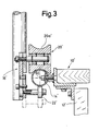
- the embodiment according to FIG. 3 differs only in the type of guidance of a carriage 16 'from the embodiment according to FIGS. 1 and 2. In the cutting machine according to FIG.
- a running rail 14' with a circular cross section on a frame 12 'for a support 10'
- the carriage has two support rollers 20 'with a circular arc-shaped running surface 20a', the curvature of which is adapted to the outer radius of the running rail 14 '.
- the carriage 16 ' has at least one support roller 22' centrally below the support rollers 20 ', so that the carriage can tilt about the longitudinal central axis of the running rail 14'. It is particularly advantageous in this embodiment that the tilt axis 66 'is only very slightly below the surface of the support 10'.
- an upper and a lower running rail 104 or 106 for a carriage 108 are mounted on a frame 102 carrying a support 100, which carriage has two carrying rollers 110 for the running rail 104 and two supporting rollers 112 for the running rail 106.
- a rack 116 is fastened to the frame 102 below the running rail 104 and engages with a pinion 120 which can be driven by an electric gear motor 118.
- the geared motor 118 can be switched on and off via an electrical switch 122 and switched in its direction of rotation, this switch being fitted above the push knife machine 48.
- FIG. 4 shows a possibility for relieving the weight of the support 54: on the side of the column 130 opposite the extension 26, a support arm 200 is attached to the latter, along which a counterweight 202 can be displaced.
- a locking screw 204 serves to fix the counterweight 202 in a position in which the base plate 56 only rests on the support 100 with a slight force.
- the support arm 200 can be kept relatively short.
- first pivot bearing e.g. the pivot bearing 28 in the embodiment according to FIG. 1 could also be provided between the carriage and the column, although such an embodiment is not preferred because it would then no longer be possible to use the rigid arm 60 to move the carriage along the support move.
- the tilting bearing 132 could also be somewhat higher or the column 130 could extend down to below the support 100, so that the column would consist of two parts pivotally connected to one another via the tilting bearing.
- All embodiments are particularly advantageous in which the approximately horizontally extending tilt axis about which the boom carrying the cutting device can be pivoted is approximately at the level of the support for the flat material or slightly above or below it. Manufacturing tolerances with regard to the height of the tilt axis then play the least role.
- Are there upper and lower guides for the carriage e.g. If the elements 20 and 22 in the embodiment according to FIGS. 1 and 2 or the elements 104 and 106 or 110 and 112 in the embodiment according to FIG. 4 are provided, it is advisable to arrange the tilting axis approximately at the level of the upper carriage guide .
- the carriage carrying the boom can be tilted together with the boom, the carriage can be made much simpler and lighter, and it no longer has to be held on its guides as stably and precisely as is the case with the known cutting machines of the type in question here is.
Landscapes
- Life Sciences & Earth Sciences (AREA)
- Forests & Forestry (AREA)
- Engineering & Computer Science (AREA)
- Mechanical Engineering (AREA)
- Treatment Of Fiber Materials (AREA)
- Sawing (AREA)
- Processing Of Stones Or Stones Resemblance Materials (AREA)
- Nonmetal Cutting Devices (AREA)
- Control Of Cutting Processes (AREA)
Applications Claiming Priority (2)
| Application Number | Priority Date | Filing Date | Title |
|---|---|---|---|
| DE3414123 | 1984-04-14 | ||
| DE19843414123 DE3414123A1 (de) | 1984-04-14 | 1984-04-14 | Zuschneidemaschine fuer flachmaterial |
Publications (2)
| Publication Number | Publication Date |
|---|---|
| EP0159526A1 true EP0159526A1 (fr) | 1985-10-30 |
| EP0159526B1 EP0159526B1 (fr) | 1989-02-01 |
Family
ID=6233575
Family Applications (1)
| Application Number | Title | Priority Date | Filing Date |
|---|---|---|---|
| EP85103064A Expired EP0159526B1 (fr) | 1984-04-14 | 1985-03-16 | Appareil pour la coupe de matière plate |
Country Status (6)
| Country | Link |
|---|---|
| US (1) | US4617737A (fr) |
| EP (1) | EP0159526B1 (fr) |
| JP (1) | JPS6114891A (fr) |
| DE (2) | DE3414123A1 (fr) |
| ES (1) | ES8607441A1 (fr) |
| FI (1) | FI84501C (fr) |
Cited By (1)
| Publication number | Priority date | Publication date | Assignee | Title |
|---|---|---|---|---|
| ITMI20090428A1 (it) * | 2009-03-20 | 2010-09-21 | Giovanni Brunini | Banco di taglio motorizzato di fogli di tessuti compositi secondo una desiderata sagomatura |
Families Citing this family (6)
| Publication number | Priority date | Publication date | Assignee | Title |
|---|---|---|---|---|
| US5111582A (en) * | 1991-09-09 | 1992-05-12 | Eastman Machine Company | Ergonomic handle for cutting machine |
| US5853036A (en) * | 1997-11-07 | 1998-12-29 | Welch; Robert S. | Contoured molding cutting apparatus |
| RU2219047C1 (ru) * | 2002-05-24 | 2003-12-20 | Кульбацкий Евгений Борисович | Режущее устройство |
| US9037284B2 (en) * | 2009-06-01 | 2015-05-19 | Dalian Huarui Heavy Industry Group Co., Ltd. | Numerical control cutting machine |
| CN105908482A (zh) * | 2016-06-02 | 2016-08-31 | 苏州道格拉斯纺织有限公司 | 一种纺织品检测裁样装置 |
| JP2018167337A (ja) * | 2017-03-29 | 2018-11-01 | ブラザー工業株式会社 | 加工装置 |
Citations (4)
| Publication number | Priority date | Publication date | Assignee | Title |
|---|---|---|---|---|
| US2998651A (en) * | 1955-08-30 | 1961-09-05 | Emil Hoogland Fa | Cutting machine for cutting textile or other material |
| FR2345054A7 (fr) * | 1976-03-16 | 1977-10-14 | Krauss & Reichert Maschf | Machine a decouper des materiaux plats, en particulier des etoffes |
| EP0057782A2 (fr) * | 1981-02-06 | 1982-08-18 | N.C.A. Co. LTD. | Machine à couper les tissus |
| EP0089006A1 (fr) * | 1982-03-11 | 1983-09-21 | Krauss u. Reichert GmbH + Co. KG Spezialmaschinenfabrik | Machine de coupe |
Family Cites Families (3)
| Publication number | Priority date | Publication date | Assignee | Title |
|---|---|---|---|---|
| FR350875A (fr) * | 1905-01-19 | 1905-06-28 | E Cornely Et Fils Soc | Machine à découper les tissus |
| US1663267A (en) * | 1922-11-02 | 1928-03-20 | Int Register Co | Means for cutting |
| DE3132127C2 (de) * | 1981-08-14 | 1984-10-18 | Krauss U. Reichert Gmbh + Co Kg Spezialmaschinenfabrik, 7012 Fellbach | Zuschneidevorrichtung für Flachmaterial wie Stoffe, Folien und dergleichen |
-
1984
- 1984-04-14 DE DE19843414123 patent/DE3414123A1/de not_active Withdrawn
-
1985
- 1985-03-16 EP EP85103064A patent/EP0159526B1/fr not_active Expired
- 1985-03-16 DE DE8585103064T patent/DE3568000D1/de not_active Expired
- 1985-03-29 US US06/717,627 patent/US4617737A/en not_active Expired - Fee Related
- 1985-04-12 ES ES542210A patent/ES8607441A1/es not_active Expired
- 1985-04-12 FI FI851468A patent/FI84501C/fi not_active IP Right Cessation
- 1985-04-15 JP JP60080052A patent/JPS6114891A/ja active Pending
Patent Citations (4)
| Publication number | Priority date | Publication date | Assignee | Title |
|---|---|---|---|---|
| US2998651A (en) * | 1955-08-30 | 1961-09-05 | Emil Hoogland Fa | Cutting machine for cutting textile or other material |
| FR2345054A7 (fr) * | 1976-03-16 | 1977-10-14 | Krauss & Reichert Maschf | Machine a decouper des materiaux plats, en particulier des etoffes |
| EP0057782A2 (fr) * | 1981-02-06 | 1982-08-18 | N.C.A. Co. LTD. | Machine à couper les tissus |
| EP0089006A1 (fr) * | 1982-03-11 | 1983-09-21 | Krauss u. Reichert GmbH + Co. KG Spezialmaschinenfabrik | Machine de coupe |
Cited By (1)
| Publication number | Priority date | Publication date | Assignee | Title |
|---|---|---|---|---|
| ITMI20090428A1 (it) * | 2009-03-20 | 2010-09-21 | Giovanni Brunini | Banco di taglio motorizzato di fogli di tessuti compositi secondo una desiderata sagomatura |
Also Published As
| Publication number | Publication date |
|---|---|
| DE3568000D1 (en) | 1989-03-09 |
| ES542210A0 (es) | 1986-05-16 |
| FI84501C (fi) | 1991-12-10 |
| JPS6114891A (ja) | 1986-01-23 |
| ES8607441A1 (es) | 1986-05-16 |
| FI851468A0 (fi) | 1985-04-12 |
| FI84501B (fi) | 1991-08-30 |
| EP0159526B1 (fr) | 1989-02-01 |
| DE3414123A1 (de) | 1985-10-17 |
| FI851468L (fi) | 1985-10-15 |
| US4617737A (en) | 1986-10-21 |
Similar Documents
| Publication | Publication Date | Title |
|---|---|---|
| EP0743395B1 (fr) | Dispositif pour meuler des rails | |
| EP0405234B1 (fr) | Appareil radiologique mobile | |
| EP2452664B1 (fr) | Table d'opération | |
| EP0088956B1 (fr) | Fauteuil de dentiste | |
| DE69917847T2 (de) | Verfahren und Vorrichtung zum Schneiden von Holzplatten | |
| EP1614650B1 (fr) | Monte-escalier | |
| EP0160869A2 (fr) | Support pour écran de données | |
| EP0082274A1 (fr) | Procédé et dispositif pour le découpage de tuyaux avec un chalumeau commandé automatiquement | |
| EP0159526B1 (fr) | Appareil pour la coupe de matière plate | |
| DE4030066C2 (de) | Mähdrescher mit einem zweiteiligen frontseitigen Schneidwerk | |
| WO1993018700A1 (fr) | Machine a nettoyer des planchers | |
| EP0678443B1 (fr) | Train de roulement, notamment pour machines de travail mobiles et véhicules | |
| EP0083678B1 (fr) | Machine de coupe angulaire | |
| AT410913B (de) | Auflagetisch für eine trennsäge mit einem maschinentisch | |
| DE8411752U1 (de) | Zuschneidemaschine fuer flachmaterial | |
| EP3449887B1 (fr) | Partie formant pied pour une colonne de support et une table d'opération comportant une surface destinée à supporter un patient | |
| EP0372232B1 (fr) | Chaise, notamment chaise de travail ou chaise de bureau | |
| DE4311778C2 (de) | Verfahrbarer Fugenschneider | |
| CH627391A5 (en) | Holder for the wire-shaped eroding electrode of an electrical discharge machine | |
| EP3144264B1 (fr) | Dispositif de levage | |
| DE4031838A1 (de) | Rollenpruefstand fuer ein kraftfahrzeug | |
| DE19917535A1 (de) | Parallelanschlagsvorrichtung für eine Formatsägemaschine | |
| DE29508568U1 (de) | Zusatzarbeitsfläche für eine Bearbeitungsmaschine | |
| DE4033715C1 (en) | Raised floor for building - has sports tracks formed by segments each tilted by spindle | |
| AT405234B (de) | Verfahrbares traggestell für wenigstens ein schneidwerkzeug für hecken, insbesonders für eine heckenschere |
Legal Events
| Date | Code | Title | Description |
|---|---|---|---|
| PUAI | Public reference made under article 153(3) epc to a published international application that has entered the european phase |
Free format text: ORIGINAL CODE: 0009012 |
|
| AK | Designated contracting states |
Designated state(s): DE FR GB IT SE |
|
| 17P | Request for examination filed |
Effective date: 19860426 |
|
| 17Q | First examination report despatched |
Effective date: 19870819 |
|
| GRAA | (expected) grant |
Free format text: ORIGINAL CODE: 0009210 |
|
| AK | Designated contracting states |
Kind code of ref document: B1 Designated state(s): DE FR GB IT SE |
|
| GBT | Gb: translation of ep patent filed (gb section 77(6)(a)/1977) | ||
| REF | Corresponds to: |
Ref document number: 3568000 Country of ref document: DE Date of ref document: 19890309 |
|
| ET | Fr: translation filed | ||
| ITF | It: translation for a ep patent filed | ||
| REG | Reference to a national code |
Ref country code: GB Ref legal event code: 727 |
|
| REG | Reference to a national code |
Ref country code: GB Ref legal event code: 727A |
|
| PLBE | No opposition filed within time limit |
Free format text: ORIGINAL CODE: 0009261 |
|
| STAA | Information on the status of an ep patent application or granted ep patent |
Free format text: STATUS: NO OPPOSITION FILED WITHIN TIME LIMIT |
|
| 26N | No opposition filed | ||
| REG | Reference to a national code |
Ref country code: GB Ref legal event code: 727B |
|
| REG | Reference to a national code |
Ref country code: GB Ref legal event code: SP |
|
| PGFP | Annual fee paid to national office [announced via postgrant information from national office to epo] |
Ref country code: GB Payment date: 19930316 Year of fee payment: 9 |
|
| PGFP | Annual fee paid to national office [announced via postgrant information from national office to epo] |
Ref country code: SE Payment date: 19930322 Year of fee payment: 9 |
|
| PGFP | Annual fee paid to national office [announced via postgrant information from national office to epo] |
Ref country code: FR Payment date: 19930326 Year of fee payment: 9 |
|
| ITTA | It: last paid annual fee | ||
| PGFP | Annual fee paid to national office [announced via postgrant information from national office to epo] |
Ref country code: DE Payment date: 19930426 Year of fee payment: 9 |
|
| PG25 | Lapsed in a contracting state [announced via postgrant information from national office to epo] |
Ref country code: GB Effective date: 19940316 |
|
| PG25 | Lapsed in a contracting state [announced via postgrant information from national office to epo] |
Ref country code: SE Free format text: LAPSE BECAUSE OF NON-PAYMENT OF DUE FEES Effective date: 19940317 |
|
| GBPC | Gb: european patent ceased through non-payment of renewal fee |
Effective date: 19940316 |
|
| PG25 | Lapsed in a contracting state [announced via postgrant information from national office to epo] |
Ref country code: FR Effective date: 19941130 |
|
| PG25 | Lapsed in a contracting state [announced via postgrant information from national office to epo] |
Ref country code: DE Effective date: 19941201 |
|
| REG | Reference to a national code |
Ref country code: FR Ref legal event code: ST |
|
| EUG | Se: european patent has lapsed |
Ref document number: 85103064.3 Effective date: 19941010 |